Table of Contents
Advertisement
Quick Links
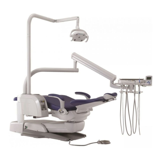
Evogue Dental Unit
This manual provides installation instructions for the Evogue unit.
The instructions contained in this booklet should be thoroughly read and
understood before installing the chair and unit.
After the installation has been completed, keep this manual in a safe place and
refer to it for future maintenance.
Installation should be conducted by authorized personnel only.
Follow instructions on installation manual.
IMPORTANT
INSTALLATION
INSTRUCTIONS
R
Advertisement
Table of Contents

Related Manuals for Belmont Quolis Series


Summary of Contents for Belmont Quolis Series
- Page 1 Evogue Dental Unit INSTALLATION INSTRUCTIONS IMPORTANT This manual provides installation instructions for the Evogue unit. The instructions contained in this booklet should be thoroughly read and understood before installing the chair and unit. After the installation has been completed, keep this manual in a safe place and refer to it for future maintenance.
- Page 3 Intended Use of the Product This product is an active therapeutic device intended to administer or exchange energy of electric, air and water for the exclusive use for diagnoses, treatments and relative procedures of dentistry, and its characteristic is not in a potentially hazardous way between such energy and human body, taking account of the nature, the density and site of application of the energy.
-
Page 4: Table Of Contents
TABLE OF CONTENTS Page 1. Overview and Major Components -----------------------------------------------------1 1-1. Swing Mounted Delivery System with Vac Pac and CLESTA LED Light 1-2. Over the Patient Delivery System with Cuspidor and CLESTA LED Light 2. Dimensions and Specifications ----------------------------------------------------------3 2-1. Swing Mounted Delivery System with Vac Pac and CLESTA LED Light 2-2. -
Page 5: Overview And Major Components
1. Overview and Major Components 1-1. Swing Mounted Delivery System with Vac Pac and CLESTA LED Light (12) Dental Light (1) Control Head (13) Dental Light Swing Arm (2) Main Control Panel (14) Light Pole (3) Handpiece Hose (15) Assistant Instrument Holder (4) Handle (16) HVE (5) Handpiece Holders... -
Page 6: Over The Patient Delivery System With Cuspidor And Clesta Led Light
1. Overview and Major Components 1-2. Over the Patient Delivery System with Cuspidor and CLESTA LED Light (1) Control Head (14) Light Pole (2) Main Control Panel (15) Assistant Instrument Holder (3) Handpiece Hose (16) HVE (4) Handle (17) Saliva Ejector (5) Handpiece Holders (18) Assistant’s Syringe (*) (6) Dr’s Syringe (*) -
Page 7: Dimensions And Specifications
2. Dimensions and Specifications 2-1. Swing Mounted Delivery System with Vac Pac and CLESTA LED Light 2-1-1. Dimensions min 103” min 20.9” - Inch / (mm) - Tolerance (± 10%) Upper Arm 125° Lower Arm 92° 125° 36.6” 25.6” Minimum dimension for change to right and left position excluding treatment space. -
Page 8: Over The Patient Delivery System With Cuspidor And Clesta Led Light
2. Dimensions and Specifications 2-2. Over the Patient Delivery System with Cuspidor and CLESTA LED Light 2-2-1. Dimensions min 103” min 20.9” - Inch / (mm) - Tolerance (± 10%) Minimum dimension excluding treatment space 10° ° 70.1” 2-2-1. Specifications Power Consumption------------------------------- AC120V 1.6A Frequency------------------------------------------- 60 Hz Fuse value------------------------------------------- M6AL, 250V... -
Page 9: Introduction
3. Introduction 3-1. Precautions for installation • Do not connect to power supply other than 120V/60Hz. • Ground the unit properly. • Attach the junction box firmly to the floor. • When electric micromotor (option) or electric scaler (option) is installed, please refer to the manual for the each device. -
Page 10: Installation For Swing Mounted Delivery System With Vac Pac
Box No.3 (Doctor’s control) (1) Doctor's control assembly 1 set (2) Junction box assembly 1 set • Junction box with cover 1 set • Duct hose 800mm 1 pc. • Utility package (air) (3) Balance arm end cap 1pc. (4) Stainless tray and non-slip pad 1 set (5) Foot controller 1 set (6) Syringe parts 1 set (7) Operating manual, installation manual 1 set... -
Page 11: How To Install The Dr. Swing Arm
5. Installation for Swing Mounted Delivery System with Vac Pac 5-1. How to Install the Dr. Swing Arm The swing arm assembly shall be mounted at the front of the chair under the seat. CAUTION Be sure to remove the carriage bolt from the chair before lift the chair by upper structure. This could cause damage to the chair if operate the chair without removing the carriage bolt. -
Page 12: How To Install The Balance Arm For The Doctor's Control
5-2. How to Install the Balance Arm for the Doctor’s Control Balance arm cover CAUTION If Vac Pac is installed with Dr. table, run tubings for Vac Pac at the same time. 1. Lower the chair. 2. Insert the balance arm into the top of the swing arm. 3. -
Page 13: How To Install The Vac Pac Section
5-3. How to Install the Vac Pac Section CAUTION If swing arm Dr. table is installed with Vac Pac, run tubings for Dr. table or at the same time. 1. Remove four screws M5 x 15mm and the flange cover of the chair. 2. -
Page 14: How To Plumb The Junction Box
5-5. How to Plumb the Junction Box Duct Hose 1. Cut the duct hose to desired length and insert it between retainers inside of the pump cover and the junction box. 2. Attach the manual on/off valve to the air supply pipe. Purge air through valve to clean debris. -
Page 15: Installation For Over The Patient Delivery System With Cuspidor (Pmu)
6. Installation for Over the Patient Delivery System with Cuspidor (PMU) 6-1. How to Install the PMU The PMU shall be mounted at the front of the chair under the seat. Seat Frame 1. Raise the seat frame of the chair as shown. CAUTION Failure to lift seat frame as shown can result in damage to paint finish of swing arm in subsequent steps. - Page 16 8. Attach PMU onto the PMU mounging bracket by aligning guide bolt with recess in front of the PMU mounting bracket and slide guide bolt into slot. Temporarily fix with three M8 x 20 cap bolts. 9. Adjust the level of the PMU with four M8 x 10 set screws.
-
Page 17: How To Install The Doctor Table
6-2. How to Install the Doctor Table 1. Insert the doctor table assy into the top of the doctor Doctor Table Assy arm. Doctor Arm 2. Slide the balance arm cover off from the balance arm and route tubing and cables down into doctor arm. Balance Arm Cover Make sure that the hoses are not twisted. - Page 18 5. Route the tubing from cuspidor through under the PMU mounting bracket. Attach the hose cover to bottom of PMU mounting bracket and fit it with truss four screws M4 x 16. PMU Mounting Bracket Hose Cover 6. Route tubing down through the chair between the main link axis and sub link axis.
-
Page 19: How To Install The Junction Box
6-3. How to Install the Junction Box Refer to floor template for connection of water, air, power, drain hose and vacuum hose. 1. Open the junction box cover by removing two slotted M5 x 10mm screws from each side of the Junction box cover. - Page 20 4. As below drawing shows, connect tubings. PMU Type (Table + Spittoon + Vacuum) 1/8 Orange 1/4 Yellow Output air to Pilot air to 1/8 Brown PMU, Dr Table main switch Pilot air from main switch 1/4 Yellow Output air to 1/4 Green Output water to Bowl flush...
-
Page 21: How To Connect Chair Operation Cable Of The Dr Table
7. How to Connect Chair Operation Cable of the Dr table 1. Connect the trunk line of the chair operation to the harness Harness from from Dr.table. (Note : Trunk line of the chair operation is Dr. table (Chair Operation) supplied from unit package) 2. -
Page 22: How To Install The Foot Controller
3. Install the monitor mount to the monitor arm. 4. Connect the cables inside Junction box. Note : LCD monitors are not supplied from Belmont. The mounting holes on back of monitor should be designed for attachment of 75 or 1000 mm VESA mgt pattern. -
Page 23: How To Install The Dental Light
10. How to Install the Dental Light 1. Installation of the dental light. Please refer to the installation instruction of the dental light. 2. Position the swing arm to either side of the chair and lock it in Locking Pin place with the dental light locking pin. -
Page 24: Installation For Power Supply Box
11. Installation for Power Supply Box (Micromotor, Electric Scaler and Fiber Optic) This power supply box is power of the micromotor, electric scaler and fiber optic. Power Supply Box 1. Place the power supply box into the junction box. Connect the power supply cable to the outlet. -
Page 25: Installation Of Accessories
Installation of Accessories Nozzles Install the cupfiller nozzle, bowl flush nozzle, cap and basket strainer to spittoon. Basket Strainer Installation of Covers 14-1. Swing Arm Bottom Cover Swing arm bottom cover Attach the lower tubing cover to the bottom of the swing arm mounting bracket with four M5 x 16mm. -
Page 26: Final Adjustment
15. Final Adjustment CAUTION Be careful when opening the Dr table top cover during installation or repair. Harness from membrane switch of the table top cover is connected to the Dr table section. Do not pull the Dr table top cover excessively. This could cause damage to the harness of the membrane switch. -
Page 27: How To Adjust The Swing Arm Friction
15-2. How to Adjust the Swing Arm Friction The friction of the swing arm for Doctor's control, Set screw dental light and monitor must be adjusted independently. Set screw Adjust the M6 x 5mm socket set screw beneath the swing arm. 15-3. -
Page 28: Drive Air
15-7. Drive Air CAUTION To avoid potential damage to handpieces - Never operate a handpiece without a bur in the chuck. - Do not exceed manufacturers recommended pressure setting at the handpiece. Each handpiece drive air can be adjusted by turning the Drive air pressure gauge drive air adjustment screw during the operation. -
Page 29: Assistant's Syringe (Vac Pac)
15-11. Assistant’s Syringe (Vac Pac) Assistant’s syringe flow control pinch valves are located inside the Vac Pac utility center. Open the upper cover by loosen the screws. Adjust the water and air flow by pinch valves. Assistant’s Syringe Flow Control Knobs (water & air) Increase Decrease Phillips... -
Page 30: Electrical Diagram
16. Electrical Diagram (with Mocromotor, Electric Scaler, Handpiece Optic) Scaler Motor HP F.O. Scaler Motor HP F.O. - 26 -... -
Page 31: Flow Diagram
17. Flow Diagram 17-1. Doctor's Control Section (with spittoon) Dr table with spittoon Auto Select Valve Inline Filter Handpiece Pressure Pull Back Valve Gauge T-Joint Master Switch T-Joint Red (1/4"O.D. x .160 I.D.) Blue ( 1/8"O.D. x .066 I.D.) Flushout Switch Brown (1/8"O.D. -
Page 32: Doctor's Control Section (Without Spittoon)
17-2. Doctor's Control Section (without spittoon) Dr table without spittoon Auto Select Valve Inline Filter Handpiece Pressure Pull Back Gauge Valve T-Joint Master Switch Red (1/4"O.D. x .160 I.D.) Blue ( 1/8"O.D.x .066 I.D.) Brown (1/8"O.D.x .066 I.D.) Orange (1/8"O.D. x .066 I.D.) Clear (1/8"O.D.x .066 I.D.) T-Joint Flushout Switch... -
Page 33: Swing Arm Section
17-3. Swing Arm Section Swing Arm Do not connect - 29 -... -
Page 34: Pmu Section
17-4. PMU Section Cup Filler Nozzle Bowl Flush Nozzle Cup Filler Switch Bowl Flush Switch Cuspidor Bowl Remote Toggles 1/8"O.D. x 1/16"I.D. TWIN TUBE Blue (1/8"O.D. x .066 I.D.) Yellow (1/4"O.D. x .160 I.D.) to Doctor Brown (1/8"O.D. x .066 I.D.) Table Orange (1/8"O.D. -
Page 35: Vac Pac Section
17-5. Vac Pac Section Solid Collector Manifold Pinch Valve Manifold H2O Outlet Flow Control Pinch Water Air / Water Valve Quick Connecter (Female) - 31 -... -
Page 36: Junction Box Section
17-6. Junction Box Section Swing Arm Table 1/8 Brown To swing arm bottle water 1/8 Brown 1/4 Yellow Pilot air from main switch Output air to table, F/C 1/8 Blue Water to table 1/4 Blue Water from Bottle 1/8 Orange Pilot air to main switch Swing Arm Table + Vac Pac 1/8 Brown... - Page 37 PMU Type (Table + Spittoon + Vacuum) 1/4 Yellow 1/8 Brown Output air to PMU/table, F/C Pilot air from main switch 1/4 Green Water to bowl flush Water 1/8 Orange Pilot air to main switch PMU Type (Table + Spittoon) 1/8 Brown 1/4 Yellow Pilot air from...
- Page 38 PMU Type (Spittoon + Vacuum) 1/8 Brown 1/4 Yellow Pilot air from Output air to PMU main switch 1/4 Green Water to bowl flush Water 1/8 Orange Pilot air to main switch PMU Type (Spittoon) 1/8 Brown 1/4 Yellow Pilot air from Output air to PMU main switch 1/4 Green...
-
Page 39: Floor Template
18. Floor Template 10-1/8 GRAVITY DRAIN 5-5/8 (1-1/2 NORMAL PIPE) 4-3/8 (1/2 THREADED PIPE) ELECTRICAL CONDUIT FOR QUAD BOX (1/2 O.D.) WATER (For option) (1/2 THREADED PIPE) TELECOMMUNICATIONS (1-1/2 NORMAL PIPE) DENTAL LIGHT TRANSFORMER CENTRAL VACUUM (5/8 O.D. TUBE) 5-5/8 DOCTOR UNIT TRANSFORMER CENTRAL VACUUM... - Page 40 BELMONT EQUIPMENT, Division of Takara Belmont USA, Inc. 101 Belmont Drive, Somerset, New Jersey 08873 U.S.A. TEL.:(732) 469-5000 / (800) 223-1192 Fax.:(732)526-6322 / (800) 280-7504 TAKARA CO, CANADA LTD. 2076 S. Sheridan Way, Mississauga, Ont., L5J2M4, Can. TEL.:(905) 822-2755 Fax.:(905)822-6203 BELMONT MANUFACTURING CO., LTD.
Need help?
Do you have a question about the Quolis Series and is the answer not in the manual?
Questions and answers