Table of Contents
Advertisement
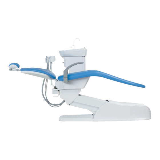
DENTAL UNIT AND CHAIR
IMPORTANT
This manual provides installation instructions for Belmont VOYAGER II.
The instructions contained in this booklet should be thoroughly read and
understood before attempting installation of chair and unit.
After the installation is completed, file this manual and refer back to it for
future maintenance.
INSTALLATION
INSTRUCTIONS
Advertisement
Table of Contents

Related Manuals for Belmont Voyager 2


Summary of Contents for Belmont Voyager 2
- Page 1 INSTALLATION INSTRUCTIONS IMPORTANT This manual provides installation instructions for Belmont VOYAGER II. The instructions contained in this booklet should be thoroughly read and understood before attempting installation of chair and unit. After the installation is completed, file this manual and refer back to it for...
-
Page 3: Table Of Contents
TABLE OF CONTENTS Page 1. Overall View and Major Components ----------------------------------------- 1 2. Dimentions and Specifications 2-1. Dimentions ------------------------------------------------------------------- 2 2-2. Specifications ---------------------------------------------------------------- 2 3.Installation Instructions 3-1. Pre-Installation Requirements --------------------------------------------- 3 3-2. Unpacking -------------------------------------------------------------------- 6 3-3. Installation Instructions for Stop Valve ---------------------------------- 7 3-4. -
Page 4: Overall View And Major Components
1. OVERALL VIEW AND MAJOR COMPONENTS Fig.1-1-1 Overall View and Major Parts MAJOR PARTS Unit Section Seat Light Pole Seat Cover Cuspidor Bowl Armrest Cuspidor Unit Foot Switch Assistant Holder Power Switch Doctor Table Pump Cover Doctor Arm J-Box Cover Doctor Arm Cover Presuure Gauge Foot Control... -
Page 5: Dimentions And Specifications
2. DIMENSIONS AND SPECIFICATIONS 2-1. DIMENSIONS -mm- Fig.2-1-1 Dimensions 2-2. SPECIFICATIONS Chair Section Seat initial Height --------------------- 460mm Seat Lifting Stroke -------------------- 380mm Backrest Movement ------------------- 0˚ ~ 72˚ above Horizontal Auto Movements ---------------------- 2 Preset, 1 Last Position Memory and 1 Auto Return Control Voltage ------------------------ DC12V Power Consumption ------------------- 115V, 50/60Hz, 7.2A/5.6A... -
Page 6: Installation Instructions
3. INSTALLATION INSTRUCTIONS 3-1. PRE-INSTALLATION REQUIREMENTS A. General Requirements (1) The contractor is to supply the necessary service and materials to complete the installation of the satisfaction of the dentists and the installation engineer. (2) This includes the supply and installation of the electric power supply cables with main isolating switch and fuses, air supply piping, water supply piping, suction piping including vacuum pump and its control wires and drain piping as noted on the installation diagrams. - Page 7 (4) Regarding installation of the vacuum pump and its connection to main suction line, follow the specifications of central vacuum pump system manufacture's recommendation. (5) All Piping should be arranged avoiding bend as much as possible. D. Air Supply Requirements (1) Compressed air to be supplied should be filtered.
- Page 8 Tap for J-Box Drain Pipe Min. 1170 Min. 930 Vacuum Water Supply Operaing Vacuum Drain Pipe Piping Air Supply Power Source PT1/2 Floor Line Fig.3-1-1 Setting Position and Plumbing Layout...
-
Page 9: Unpacking
3-2. UNPACKING A. Checking the packages and Unpacking The VOYAGER II is to be delivered into four packages. (Chair base section, Chair upper section,Unit section and Dental Light) B. Checking Contents Check the contents of each packing with following list. (1) Chair Base Section ------------------------------------------------------- 1set 1.Chair Base Assembly (Base, Base Cover, Pump Cover) - Page 10 3-3. INSTALLATION OF STOP VALVES (1) Confirm that the pipings and wirings are laid out Chair Base Chair Base in accordance with Fig.3-1-1. (2) Install water and air stop valves to each supply pipe. Water Stop Valve The direction of stop valves are shown in Fig.3-3-1. Drain Pipe Air Stop Valve (3) After installation of the stop valves, open the...
- Page 11 3-5. INSTALLATION OF UNIT (1) Remove all the staples fixing the carton to pallet, or cut the carton just above the Staples stapled line, and remove the carton. (Fig.3-5-1) (2) Place the unit section with pallet behind the Fig.3-5-1 Unit Section Carton planned location for unit.
- Page 12 (6) Plug the power supply cable. Raise the upper structure by the foot switch to the highest position. Upper Flange Cover Remove a frange cover, upper frange cover and Front Flange Cover. (Fig.3-5-6) Front Flange Cover Flange Cover Upper Sub Link Cover Fig.3-5-6 Removing Covers from Pallet (7) Remove a lag bolt (B) and remove the cuspidor Bolt (B)
- Page 13 (10) Run the drain hose, vacuum hose and tubings through link part. (Fig.3-5-10) Fix the hose bracket to sub link by two pan screws. (Fig.3-5-10 A view) Fix the drain hose and vacuum hose to base plate by hose fixing metal. Vacuum Hose Tubings Sub LInk...
- Page 14 (16) Remove a lag bolt (A) and remove the doctor table unit from the pallet. Lag Bolt (A) (Fig.3-5-13) Doctor Table Fig.3-5-13 Removing Doctor Table from Pallet Ring Nut (17) Set flat washers, thrust bearings and Thrust Bearing the doctor table swing arm to the Flat Washer swing arm shaft on the chair and fix them with ring nut.
- Page 15 3-6. INSTALLATIONS OF UTILITY SECTION Chair Base (1) Drain Hose and Vacuum Hose Connection (Fig.3-6-1) 1. Run the drain hose and vacuum hose through Utility Section under utility section frame. Frame 2. Cut the drain hose and vacuum hose from the chair at suitable length and connect them to Drain Elbow Vacuum Hose...
- Page 16 3-7. INSTALLATIONS OF CHAIR (UPPER PART) CAUTION Confirm that Red Tagged Bolt and Red Tagged Plugs are removed ( Step 3-4 (5) (6)) Back Support Plate M8x20 Cap Bolt Raise the backrest by the foot switch to the upright position. Note : Refer to the operating manual for chair operation.
- Page 17 (9) Fix the seat to the base section. (Fig.3-7-5) Hook 2 x fixing hooks into the seat support bars and fix the seat to the seat support bars with two pan head screws(M6-35) and flat washers. Seat Pan Head Screw (M6-35) with Flat Washer Seat Fixing Hook Seat...
- Page 18 3-8. INSTALLATION OF DENTAL LIGHT (1) Fix the light post under the chair flange with 2-M10 Socket Head Cap Bolt (M10-20) . (Fig.3-8-1) Chair Flange (2) Pass the light cable through the light pole and insert the light spigot into the light Light Post post, and fix it with two button head screws Socket Head Cap Bolt...
- Page 19 Light Blue (6) Switching Distance Adjustment for IO5000 Yellow Black Dental Light White Pink Dental light P.C.B. is located in the utility part. The switching distance can Blue Brown be adjusted by the potentiometer on the Orange P.C.B. (Fig.3-8-6) Dental Light Cable 1.Turning the potentiometer clockwise Fig.3-8-5 Connecting wire for IO5000 decreases the switching distance.
-
Page 20: Speed Adjustment For Chair
4. SPEED ADJUSTMENT FOR CHAIR (Fig.4-1-1 and Fig.4-1-2) Seat lowering speed and backrest reclining speed can be adjusted by the speed control screws on the solenoid valve block. Solenoid valve numbers and functions are shown in (Fig.4-1-1). 1. Remove the pump cover. 2. -
Page 21: Hydraulic Diagram For Chair
5. HYDRAULIC DIAGRAM FOR CHAIR Seat Elevation Cylinder Backrest Cylinder Solenoid Valve Block : Check Valve Motor Pump : Filter : Flow Adjustable Solenoid Valve Oil Reservoir : Solenoid Valve -18-... -
Page 22: Electrical Diagram For Chair
6. ELECTRICAL DIAGRAM FOR CHAIR -19-... -
Page 23: Flow Diagram For Unit
7. FLOW DIAGRAM FOR UNIT (CENTRAL VACUUM TYPE) -20-... - Page 24 (AIR VACUUM TYPE) -21-...
-
Page 25: Electrical Diagram For Unit
8. ELECTRIC DIAGRAM FOR UNIT Micro/air switch for doctor table Fiber Optic Handpiece Power Chair control P.C.B. Supply Light Pack P.C.B. Dental Light 048 Power 10.5V Supply Water Heater Electric Scaler PB11 Water Heater Electric Scaler P.C.B. P.C.B. Automatic Separator Option TF1 : Transformer (13VA) TF3 : Transformer (265.2VA) - Page 28 NOTE TAKARA BELMONT CORPORATION 2-1-1, Higashishinsaibashi,Chuo-ku,Osaka,Japan TEL : + 81 6 6213-5945 FAX : + 81 6 6212-3680 BOOK NO. AFES26F0 Printed in Japan 2014-06...
Need help?
Do you have a question about the Voyager 2 and is the answer not in the manual?
Questions and answers