Advertisement
Table of Contents
- 1 Table of Contents
- 2 Safety Precautions
- 3 Request for Water Flushout (Discharge)
- 4 Overall View and Major Components
- 5 Description of Operation and Functions of Components
- 6 Care and Maintanance
- 7 Storage, Lifetime, Dispodal and Restrictions of Use
- 8 Before Asking for Repairs
- 9 Dimension and Specification
- 10 Maintanance and Inspection
- Download this manual
DENTAL UNIT AND CHAIR
OPERATING INSTRUCTIONS
This Instruction Manual describes how to use the SP-CLEO II.
IMPORTANT
Thoroughly read this Instruction Manual before use, and use the SP-CLEO II according to
the instructions.
Keep this Instruction Manual carefully, and read it again whenever it is needed.
This product is a dental unit used for dental care.
People other than dentists and other dental professionals should not use this product.
Advertisement
Table of Contents

Subscribe to Our Youtube Channel
Related Manuals for Belmont SP-CLEO II


Summary of Contents for Belmont SP-CLEO II
- Page 1 This Instruction Manual describes how to use the SP-CLEO II. IMPORTANT Thoroughly read this Instruction Manual before use, and use the SP-CLEO II according to the instructions. Keep this Instruction Manual carefully, and read it again whenever it is needed.
-
Page 2: Table Of Contents
TABEL OF CONTENTS 1. SAFETY PRECAUTIONS ------------------------------------------------------------------- 2. REQUEST FOR WATER FLUSHOUT (DISCHARGE) ------------------------------ 3. OVERALL VIEW AND MAJOR COMPONENTS ------------------------------------ 4. DESCRIPTION OF OPERATION AND FUNCTIONS OF COMPONENTS --- 5. CARE AND MAINTANANCE ------------------------------------------------------------- 6. STORAGE, LIFETIME, DISPODAL AND RESTRICTIONS OF USE ----------- 7. - Page 3 600 hPa - 1060 hPa Important Notes In case of the troubles, please contat Takara Belmont offices or your dealers. Do not disassemble or attempt to repair. Disassembly, repair or modifications shoud only be done by a qualified repair technician.
- Page 4 SYMBOLS Chair auto return Chair last position Chair preset1 Chair preset2 To Recline To raise To raise the chair To lower the chair the backrest the backrest Chair auto return Chair preset1 Chair preset2 Chair last position To Recline Chair manual To raise te chair Chair auto control the backrest...
-
Page 5: Safety Precautions
1. SAFETY PRECAUTIONS For proper operation, please carefully read through the Safety Precautions before using the product. Items described herein are provided in order to ensure safe and appropriate use of the product, and to prevent property damage or personal injury to the operator and other persons. Furthermore, the precautions describe potential hazards due to improper handling and classify hazards according to degree of damage and level of urgency. - Page 6 1. SAFETY PRECAUTIONS WA R N I N G 9. Be sure to mount the mirror cover. The mirror cover for the dental light must be attached whenever the light is used. Touching the light bulb may result in burns. Refer to the operating instructions on the dental light for details.
- Page 7 1. SAFETY PRECAUTIONS C A U T I O N 8. Request for flushout of water staying in the unit In order to maintain the quality of the treatment water to stably supply water to the handpieces, be sure to thoroughly flush out any remaining water in the unit before starting treatment. Refer to the pages for the flushing out procedures.
- Page 8 1. SAFETY PRECAUTIONS C A U T I O N 20. Observe the following when cleaning the Spittoon bowl: Never use sandpaper, wire wool, or detergents containing abrasive compounds to clean the Spittoon bowl. Do not use overly acidic or alkaline pipe cleaning agents, as they may corrode metals. 21.
- Page 9 1.SAFETY PRECAUTIONS Caution Points During Operation of the Product Description of Symbol Marks Caution areas (such as moving parts, rotating parts and detachable parts to which caution should be paid) Caution areas that are provided with an emergency stop mechanism Be aware of contact with the assistant’...
-
Page 10: Request For Water Flushout (Discharge)
2. REQUEST FOR WATER FLUSHOUT (DISCHARGE) E type:Standard E Precautions for water quality safety A type:Option A C A U T I O N To maintain the water quality for treatment and for stable water supply to the handpieces, ensure to carry out flushout of the residual water in the unit before starting treatment. -
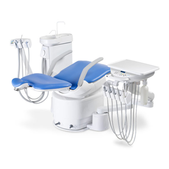
Page 11: Overall View And Major Components
3. OVERALL VIEW AND MAJOR COMPONENTS Base Mount Type Cuspidor Bowl Doctor Control Panel Assistant Instruments Holder Doctor Table Balance Arm Foot Controller Doctor Instruments Holder Manual Switch Auto Switch Main Switch - 7 -... - Page 12 3. OVERALL VIEW AND MAJOR COMPONENTS Docotor Table Section Holder Type Place Holder Type Cart Type E A E A E A Tray Mat Tray Mat Tray Mat Doctor Control Panel Doctor Control Panel Doctor Control Panel Handle Handle Handle Doctor Instruments Holder Brake Brake...
-
Page 13: Description Of Operation And Functions Of Components
4. DESCRIPTION OF OPERATION AND FUNCTIONS OF COMPONENTS 1. Chair Section 1-1. Main Switch Lit in green when the switch is on. OFF ON Main Switch 1-2. Armrest ① ② Hold the armrest on the right-hand side, and release the lock by pulling up the armrest diagonally backward (in a direction that is parallel to the armrest axis) by about 1 cm. - Page 14 4. DESCRIPTION OF OPERATION AND FUNCTIONS OF COMPONENTS 1-4. Stick Switch Auto Switch Auto Switch 1) Preset Control The chair has two preset positions. (Preset-1 and Preset-2) Momentarily depress the auto mode stick switch to left side, the chair will Manual Switch move to the preset-1 position automatically.
- Page 15 When the main switch is turned on, all the lamps on the doctor Indicator membrane switch panel light up, and the following is displayed on the indicator. E A Belmont Ver. ** ♪ Takara Belmont 0 Program version No. A few seconds later, Belmont ...
- Page 16 4. DESCRIPTION OF OPERATION AND FUNCTIONS OF COMPONENTS 2-3. Handpiece E A When the main switch is turned on, whether handpieces are accurately fitted in instrument holders or not is checked automatically. If any handpiece is not accurately fitted in its instrument holder at this occasion, the subject holder number (counted as No.
- Page 17 4. DESCRIPTION OF OPERATION AND FUNCTIONS OF COMPONENTS 2-6. Handpiece spray flow rate control The handpiece spray flow rate can be adjusted by turning knobs (with blue caps) of the doctor section. 2-7. Syringe spray water and air control The syringe water and air flow rate can be adjusted by turning knobs of the doctor section.
- Page 18 4. DESCRIPTION OF OPERATION AND FUNCTIONS OF COMPONENTS 2-9. Motion stop locking device E A E A While the doctor table is located behind the chair, auto motion stop lock is applied for preventing damage to the doctor table. Lock Auto motion stop lock is released when the doctor table is returned to the normal care position.
- Page 19 4. DESCRIPTION OF OPERATION AND FUNCTIONS OF COMPONENTS 2-13. Foot controller Type A2 (A Type) E A Pedal The pedal depressing extent can control the turbine rotation speed and air scaler output. Coolant Swtich The electric scaler (optional) is activated when the pedal is depressed.
- Page 20 4. DESCRIPTION OF OPERATION AND FUNCTIONS OF COMPONENTS 2-14. Description of membrane switch panel An overview of display on the membrane switch panel and each switch on this membrane switch panel is shown in the figure below. For datailed operating instruction please see pages 14-18. Each switch on the membrane switch panel provides multiple functions, and various actions can be set When combined with the function switch.
- Page 21 4. DESCRIPTION OF OPERATION AND FUNCTIONS OF COMPONENTS Chair manual switch E A E A E A E A Switches for manual up/down/backrest reclining of the chair. Press to raise the chair. Press to lower the chair. Press to recline the backrest. Press to get up the backrest.
- Page 22 4. DESCRIPTION OF OPERATION AND FUNCTIONS OF COMPONENTS Cuspidor bowl flush switch E A E A When this switch is pressed, water comes out of the bowl flush nozzle E A E A and flushes the cuspidor bowl. The timer is set for about 5 seconds. For continuous bowl flushing keep pressing this switch is for 2 seconds or longer.
- Page 23 4. DESCRIPTION OF OPERATION AND FUNCTIONS OF COMPONENTS Micromotor forward/reverse select switch E A Use this switch for switching the micromotor rotation direction. Pressing this switch each time changes the direction between For forward turning For reverse turning (Only right-side LED (Only left-side LED forward (clockwise) rotation and reverse (counter-clockwise) is lit in green.)
- Page 24 4. DESCRIPTION OF OPERATION AND FUNCTIONS OF COMPONENTS Function switch E A Use this switch for setting various working conditions. The setup function changes in the sequence indicated below each time when this switch is pressed. 1. Dental timer time setup and motion 2.
- Page 25 4. DESCRIPTION OF OPERATION AND FUNCTIONS OF COMPONENTS 2-15. Micromotor operation and display E A 2-15-1. Description of micromotor rotation modes and operation Two modes, that is, limit rotation (limit mode) and preset rotation Limit Rotation (preset mode), are available for micromotor rotation. Either one of these modes can be selected by pressing this switch.
- Page 26 4. DESCRIPTION OF OPERATION AND FUNCTIONS OF COMPONENTS 2-15-4. Description of recurrence mode at the time of power on and setup This recurrence mode is the rotation mode that always appears first when a micromotor is picked up after the main switch is turned on. No.2 SET2 It is convenient if a rotation mode frequently used is set as the 20000rpm...
- Page 27 4. DESCRIPTION OF OPERATION AND FUNCTIONS OF COMPONENTS 2-17. Function switch E A 2-17-1. Contents and sequence of function switch Indicator Function Switch The contents of display on the indicator on the doctor membrane switch panel change sequentially each time when the function switch is pressed to select a desired setup. Contents and sequence of function switch setup are described below.
- Page 28 4. DESCRIPTION OF OPERATION AND FUNCTIONS OF COMPONENTS Setup of dental timer and operation A subtraction timer is built in. The maximum settable time is 90 minutes and 50 seconds, and setup in 10-second units is permitted. Preset of four different times is permitted. A preset time can be called by chair preset switch TIMER SET F=↓...
- Page 29 4. DESCRIPTION OF OPERATION AND FUNCTIONS OF COMPONENTS Selection of doctor number Chair positions and handpiece initial setup for four different Dr NUMBER=0 ↓ doctors can be stored. Micromotor preset rotation speed, and on/off statue of light pack and spray. (3 positions per each doctor) Micromotor motion state at the time of power on, and dental light switch on/off state.
- Page 30 4. DESCRIPTION OF OPERATION AND FUNCTIONS OF COMPONENTS Selection and change of key touch tone With or without beep tone that is issued when a switch is BEEP=ON F=↓ pressed can be selected, and the beep tone frequency (tone (-)=OFF (+)=ON quality) can be changed.
- Page 31 4. DESCRIPTION OF OPERATION AND FUNCTIONS OF COMPONENTS Selection of alarm sound upon time-up of dental timer The alarm sounds on termination of timer time after countdown ALARM TYPE=0 F=↓ of dental timer. 0 1 2 LP (3) PUSH Four alarm patterns are provided, and even in case where multiple chairs are installed in the same room, the chair from which the alarm sounds can be easily identified if different alarm patters are set.
- Page 32 4. DESCRIPTION OF OPERATION AND FUNCTIONS OF COMPONENTS Selection of interlocked action of cupfiller and bowl flush Selection is permitted from two procedures. =LINK F=E Case of non-interlock (-)=IND (+)=LINK Flushout of the cuspidor bowl is not implemented even after (Example) Case of interlock start-up of cupfiller.
- Page 33 4. DESCRIPTION OF OPERATION AND FUNCTIONS OF COMPONENTS 3. Cuspidor unit section 3-1. Operation and functions of control panel section ④ ③ ② ① ⑥ ⑤ Increase Decrease A W ⑨ ⑧ ⑦ Dental light select switch (optional) Switch for changing the AL-520 / AL-820S / 900 Dental light (Type 920) lighting mode. Either sensor mode or manual mode can be selected.
- Page 34 4. DESCRIPTION OF OPERATION AND FUNCTIONS OF COMPONENTS Bowl flush control knob Use this knob for controlling the bowl flush water flow rate. The flow rate decreases when the knob is turned clockwise, and the flow rate increases when the knob is turned counterclockwise. Syringe water control Make adjustment of syringe water by the syringe water control knob (with blue cap).
-
Page 35: Care And Maintanance
5. CARE AND MAINTANANCE 1. Chair Section Chair Cleaning - The surface of the chair’s seating area is made of synthetic leather. Apply dry wiping or wipe the surface with cloth moistened with either water or diluted neutral detergent for the care. - If the color of clothing or belt remained on the synthetic leather, wipe it off with cloth moistened with diluted neutral detergent as soon as possible, to avoid its... - Page 36 5. CARE AND MAINTANANCE 2. Doctor unit section Tray mat (Silicone Mat) Membrane Panel Doctor Instruments holder Waste receptacle (optional) When waste accumulates, replace paper cup as required Paper cup type Stainless cup type from waste receptacle holder ② Waste receptacle (optional) made of stainless steel is トレーマット...
- Page 37 5. CARE AND MAINTANANCE Membrane switch panel CAUTION In case the surface of the membrane switch panel is wiped with disinfectant agent or the like, fully wipe away the chemical. Membrane switch malfunction may arise if the chemical penetrates to the back face of the membrane.
- Page 38 5. CARE AND MAINTANANCE 3. Cuspidor unit section Cleaning of solid collector Remove the filter in the solid collector located in the cuspidor unit section on termination of medical treatment, and wash the filter. The vacuum suction force will drop if excessive solids are contained in the solid collector filter.
- Page 39 5. CARE AND MAINTANANCE Cleaning of vacuum handpiece body section [Disassembling and cleaning procedure] 1. Pull the cap section and body of the vacuum handpiece Valve to outside, and carry out disassembly as shown in the figure. Also remove the valve from the slide groove. Body Remove dirt with tap water before sterilization.
- Page 40 5. CARE AND MAINTANANCE Cleaning of vacuum hose and saliva ejector hose The vacuum hose and saliva ejector hose can be removed when the joint is unlocked by turning it Release counterclockwise. Therefore, they can be cleaned with Lock running water. For cleaning the vacuum hose and saliva ejector hose, turn off the main switch for the unit.
- Page 41 5. CARE AND MAINTANANCE 4. Junction box section Cleaning of air filter drain valve and water drainage from air compressor The drain valve is provided for drainage of water from the air filter. Drain the water accumulated in the air filter by turning the drain valve counterclockwise, at least once a week.
-
Page 42: Storage, Lifetime, Dispodal And Restrictions Of Use
6. STORAGE, LIFETIME, DISPODAL AND RESTRICTIONS OF USE Procedure for storage of the unit Make sure to carry out works of items described below on termination of medical treatment for the day, or when it is anticipated that the unit will not be used for a long period of time for recess or the like. 1. -
Page 43: Before Asking For Repairs
7. BEFORE ASKING FOR REPAIRS If any of phenomena described below has occurred, make the following checks before asking for repairs. Phenomenon Check point and result Action to be taken Main switch is not on. Turn on the main switch. Air compressor power is not on. -
Page 44: Dimension And Specification
8. DIMENSION AND SPECIFICATION Specification Rated power supply ------------------------------------------------- AC.115V 7.7A/6.3A 50/60Hz AC.220V 3.5A/3.5A 50/60Hz AC.230V 3.4A 50Hz AC.240V 3.6A 50Hz Fuse ------------------------------------------------------------------- 115V F10A 125V 220 - 240V F5A 250V Air main pressure --------------------------------------------------- 0.45 to 0.5MPa Water main pressure ------------------------------------------------ 0.1 to 0.2MPa Mass ------------------------------------------------------------------ Cuspidor unit section : 74kg Doctor unit section : 40kg Chair section : 150kg... - Page 45 8. DIMENSION AND SPECIFICATION Dimension (Numerical values shown here represent standard values.) Unit: mm Dimensional tolerance: ±10% Base mount type 1710 Cart type 1710 - 41 -...
-
Page 46: Maintanance And Inspection
9. MAINTANANCE AND INSPECTION Guide for daily maintenance and inspection (Maintenance and inspection by user) Management of maintenance and inspection of medical equipment should be implemented by the user (medical 保 守 点 検 institution). In case the user does not implement such management, it is permitted that such management is outsourced to a qualified entity such as a medical equipment repair company. - Page 47 保 守 点 検 9. MAINTANANCE AND INSPECTION Influence if inspection Maintenance required in case Inspection method Item Frequency not conducted of nonconformity and diagnosis Care Faulty suction may After Flush the suction line, and Clean the suction line and filter in Vacuum arise.
- Page 48 NOTE TAKARA BELMONT CORPORATION 2-1-1, Higashishinsaibashi,Chuo-ku,Osaka, 542-0083, Japan TEL : 81-6-6213-5945 FAX : 81-6-6212-3680 BOOK NO. 1E00ZXB0 Printed in Japan 2011-09...
Need help?
Do you have a question about the SP-CLEO II and is the answer not in the manual?
Questions and answers