Belmont CLESTA II Installation Instructions Manual
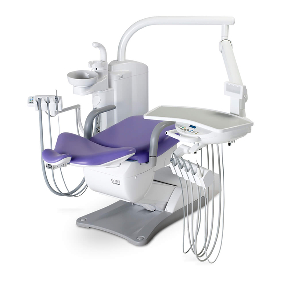
Chair (eurus type)
Hide thumbs
Also See for CLESTA II:
- Operating instructions manual (40 pages) ,
- Installation instructions manual (16 pages) ,
- Operating instructions manual (40 pages)
Table of Contents
Advertisement
Advertisement
Table of Contents

Subscribe to Our Youtube Channel
Related Manuals for Belmont CLESTA II


Summary of Contents for Belmont CLESTA II
- Page 1 CLESTA II CHAIR (EURUS TYPE) INSTALLATION INSTRUCTIONS...
-
Page 2: Table Of Contents
Table of Contents Safety Consideration Risk Level Interpretation ............3 Safety Precautions ..............5 Cautions regarding installation Precautions for installation ............6 Conditions for installation site Capacity of power supply equipment to be used ......7 Strength of the building required for installation ......7 Installation Dimensions/Environmental Requirements ........8 Dimensions ..............8... -
Page 3: Safety Consideration
Safety Consideration Risk Level Interpretation Precautions before use Make sure to carefully read the Safety Precautions and Operat- ing Precautions and use the product correctly. These precautions are intended to ensure the safe use of the product and prevent harm or damage to users or other people. According to the magnitude of harm and damage and the degree of urgency, an incident that may be caused by misuse of the product is classified into one of the following categories:... - Page 4 Safety Consideration The following graphical symbols are used to explain your responsibilities for using the product safely: Graphical symbols for prohibited activity Generally prohibited activity Disassembly, repair or modification prohibited Graphical symbol for mandatory instructions Mandatory instructions for ordinary users ...
-
Page 5: Safety Precautions
Safety Consideration Safety Precautions CONTRAINDICATION Installing or transferring the Precautions regarding installation product Do not install the product near electromagnetic sources such as communication facilities or elevators. Malfunction of this product may occur in the presence of electromagnetic interference waves. WARNING Installing or transferring the Precautions for installation... -
Page 6: Cautions Regarding Installation
Cautions regarding installation Precautions for installation 1. While carrying the chair, make sure to hold only the designated parts. If not, it may lead to physical injury. 2. Confirm that the fixing bolts are tightened before carrying the chair. 3. Take care not to topple the equipment during transportation. 4. -
Page 7: Conditions For Installation Site
1. The floor strength of the building should be ≥ 4,900 N/m 2. As the floor material of the building, plywood with the thickness of 25 mm as recommended by Takara Belmont, or a composite material that combines plywood with the thickness of 15 mm and particle board with the thickness of 20 mm, should be used. -
Page 8: Installation
Installation Dimensions/Environmental Requirements 4-1-1 Dimensions 2010 600 210 5〜18° 235° 170° 1380 Unit: mm (Dimensional tolerance:±10%) *Dimensions and specifications are subject to change without notice. 4-1-2 Environmental Requirements Usage environment Temperature 0°C to 40°C Humidity 10% to 95% Atmospheric pressure 700 to 1060 hPa Transportation/storage Temperature −20°C to 70°C environment... -
Page 9: Necessary Tools And Supplied Parts
Installation Necessary tools and supplied parts 4-2-1 Necessary tools The table below shows the necessary tools for the installation of this product. Tool name QTY. Phillips screwdriver No. 1–3 1 for each Monkey wrench (Max. opening width: 29 mm) 6-piece double head open end wrench set (5.5–24 mm) 8-piece hex key wrench set (1.5–8 mm) Level 4-2-2... -
Page 10: Installation Procedures
Installation Installation procedures 4-3-1 Installing the chair 1. Unpack the carton of the chair. Remove wood screws, M4 × 45, plated (10 pieces) for packing. 2. Remove the chair from the skid. Remove the hex head flange screw TP-A, M6 × 40 (3 pieces) that fix the base and skid. - Page 11 Installation 4. Remove the fixing bolts. Remove the cap bolt, M10 × 30, plated (1 piece). 5. Remove the rubber plug of the oil tank. 6. Attach the connector for the stick switch. Attach the connector to the one that starts with same number.
- Page 12 Installation 8. Tilt the stick switch for the chair manual operation up to lift up the chair to its highest position. 9. Attach the stick switch. Insert the connected connector into the switch, and fix the switch with pan head screws, 2P, M5 × 10, plated (2 pieces).
- Page 13 14. Attach the headrest unit. Attach the headrest unit with cap bolts, M8 × 20, plated (4 pieces). Mount the CLESTA II unit on the chair, before installing the seat, backrest, and other parts of the chair. Refer to the Unit installation instructions.
-
Page 14: Installing The Seat, Backrest, And Other Parts Of The Chair
Installation 4-3-2 Installing the seat, backrest, and other parts of the chair 1. Attach the flange cover bottom. Fix the cover with truss screws, M4 × 6, white (4 pieces). 2. Attach the flange cover spacer (1 piece each on right and left). - Page 15 Installation 5. Attach the headrest. For the manual headrest : (1) Attach the headrest to the headrest unit. Fix the headrest with the countersunk screws, M5 × 8, plated (3 pieces). (2) Attach the headrest cover. Insert the catch of the headrest cover to the headrest. 6.
- Page 16 Installation 9. Attach the seat. Hook the rear side of the seat to the seat frame and fix the front side of the seat with pan head screws, 2P, M6 × 15, plated, (2 pieces) and flat washers, 7 × 19 × 2.0 (2 pieces). 10.
- Page 17 Installation 13. Disconnect the terminal block from the connector of the power cable for the chair. (1) Disconnect the power plug that connects the terminal block from the power supply outlet. (2) Disconnect the terminal block. Terminal block PCB for chair 14.
-
Page 18: Attaching The Cover
Installation 4-3-3 Attaching the cover 1. Attach the clamps (2 pieces) on the holes of base. 2. Clamp the stick switch cable (one cable only) at the positions (2 places) of mark. Mark 3. Attach the base cover. Remove the following screws fixed temporarily on base, and fix the base cover with the following screws. - Page 19 Installation ベースカバー 4. Attach the base cover lid. Fixing screw in front If the base cover lid is difficult to attach, loosen the fixing screws on the front side. Base cover lid 5. Attach the pump cover. (1) Insert the U-shaped notch of the pump cover onto the ditch of the nut on the chair link at both sides.
-
Page 20: Flow Diagram/Wiring Diagram
Flow Diagram/Wiring Diagram Flow diagram... -
Page 21: Wiring Diagram
Flow Diagram/Wiring Diagram Wiring Diagram Auto Manual STICK SWITCH PCB STICK SWITCH PCB 1G01Q1** 1G01Q1** TL DOWN SAFE SW A TL DOWN SAFE SW C 1A0P8Y** 1A0P99** TL DOWN SAFE SW B 1A0P8Z** SEAT POTENTIO METER STICK SW CODE STICK SW CODE Connect to J-BOX Line TL BACK SAFE SW 1A0SUC**... - Page 22 NOTE...
- Page 23 NOTE...
- Page 24 TAKARA BELMONT CORPORATION 2020-02 (3rd Edition) 2-1-1, Higashishinsaibashi,Chuo-ku,Osaka, 542-0083, Japan 1E07MFCE TEL : 81-6-6213-5945 FAX : 81-6-6212-3680...
Need help?
Do you have a question about the CLESTA II and is the answer not in the manual?
Questions and answers