Table of Contents
Advertisement
Quick Links
Instruction Manual
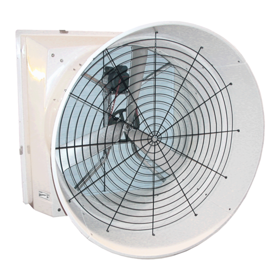
VX51 and VX55 with Munters Drive
51" and 55" Exhaust Fan
Models: VX51DFxxCT-Hx • VX51DFxxCP-Hx
VX55DFxxCT-Hx • VX55DFxxCP-Hx
© Munters Corporation, August 2018
Aerotech
VX51 & VX55
with RC Cone and
Munters Drive*
*Protected by U.S. Patent No. 6,386,828, 6616404;
6953320 and other Patents Pending
QM1190r7
1
Advertisement
Table of Contents

Related Manuals for Munters VX55


Summary of Contents for Munters VX55
- Page 1 RC Cone and Munters Drive* Instruction Manual *Protected by U.S. Patent No. 6,386,828, 6616404; 6953320 and other Patents Pending VX51 and VX55 with Munters Drive 51” and 55” Exhaust Fan Models: VX51DFxxCT-Hx • VX51DFxxCP-Hx VX55DFxxCT-Hx • VX55DFxxCP-Hx © Munters Corporation, August 2018...
- Page 2 Please Note: To achieve maximum performance and insure long life from your Munters product it is essential that it be installed and maintained properly. Please read all instructions carefully before beginning installation.
-
Page 3: Table Of Contents
PV Style Shutter 3. Electrical Wiring Recommended Wire Routing Electrical Wiring Recommended Wiring 4. Operation and Maintenance Operation Maintenance 5. Troubleshooting 6. Winterizing Winterizing Winter Weather Protection 7. Exploded View and Parts List 23 -24 © Munters Corporation, August 2018 QM1190r7... -
Page 4: Unpacking The Equipment
" ⁄ " 63 ⁄ " 62 ⁄ " 27 ⁄ " 31 ⁄ " 58 ⁄ " 25 ⁄ " 11 ⁄ " 2 ⁄ " 70" *Dimensions Plus/Minus ⁄ ", Field Verify © Munters Corporation, August 2018 QM1190r7... -
Page 5: Installation Instructions
70” Minimum Ceiling See minimum spacing notes in (see chart A) Chart A Framing Figure 1A Frame Construction Top of Post Wall 6 x 6 Post - 6'O.C. (see Chart A) Figure 1B Post Construction © Munters Corporation, August 2018 QM1190r7... - Page 6 If fan needs to be mounted, so that shutter does not stick into building then frame fan as shown in Figure 3. and sides require 4" minimum and bottom requires 2" minimum. Wall Framing 4" Minimum Framing for fan, Top and Sides 2" Minimum Framing for fan, Bottom Wall Framing Figure 3 © Munters Corporation, August 2018 QM1190r7...
- Page 7 Finger tighten nuts only at this time. Top Cone Tab Flange Nut [D] 51/55 RC Cone Hole at 10 O'clock Washer [C] 51/55RC Cone (outside) Fan Outlet (inside) Truss Head Bolt [B] Figure 5B Figure 5A © Munters Corporation, August 2018 QM1190r7...
- Page 8 Figure 6 Step 7 The snap-in guard has a slight conical shape to it so, when installed the center of the guard should protrude out slightly. See Figure 7A. 51/55 RC Cone Guard Figure 7A © Munters Corporation, August 2018 QM1190r7...
- Page 9 Line up each eyelet with a hole in the guard pads. Secure guard to cone using (8) existing Bolts and Nuts. See Figure 8A and 8B. Tighten all nuts at this time. Guard Mounting Pad Fan Outlet Bolt Guard Guard Mounting Figure 8A Guard eyelet Figure 8B © Munters Corporation, August 2018 QM1190r7...
-
Page 10: Pt Style Shutter
Figure 9 Step 11 Fasten shutter in place by rotating the side and top shutter clips over the shutter flanges. See Figure 10. Installation is now complete, proceed to Electrical Wiring Section. Figure 10 © Munters Corporation, August 2018 QM1190r7... -
Page 11: Pv Style Shutter
Fasten shutter in place by rotating the side and top shutter clips over See Figure 11B. the shutter flanges, Installation is now complete, proceed to electrical wiring section. PV Shutter Fixed Bottom Shutter Clip Figure 11A Figure 11B © Munters Corporation, August 2018 QM1190r7... -
Page 12: Electrical Wiring
3.1 Recommended Wire Routing: The Munters Drive Fan comes with a coil of electrical cable that is pre-wired to motor. Find the end of the cable and route it outside the fan and connect it to the incoming power supply and/or the safety cut-off switch. - Page 13 For electrical connection requirements, refer to diagram on motor nameplate and to information enclosed with the environmental control to be used. High Voltage, disconnect power Single Phase and Three Phase Munters Drives: Power supply for fans to have Circuit before servicing.
-
Page 14: Electrical Wiring
3.3 Recommended Wiring The Munters Drive fan ships configured for simple ON/OFF operation. When electrical power is applied to the main cable and the ‘RUN’ Switch is in the ‘ON’ Position, the fan will start and run at full speed. - Page 15 1 watertight fitting, they must be sealed on both sides of Munters Drive Box wall to prevent water infiltration. If you are going to run the Munters Drive with a signal from a control, carefully remove 6 screws and the cover and save to reinstall later.
- Page 16 Munters Drive Box, to the ‘OFF’ position. Now wire an ‘ON’ command from the ‘COMMON’ terminal to the input relay in the control and from the output of the control relay to the ‘RUN’ terminal in the Munters See Figure 13A & 13D.
- Page 17 Munters Drive Box, to the ‘OFF’ position. Now wire an ‘ON’ command from the ‘COMMON’ terminal to the input relay in the control and from the output of the relay to the ‘RUN’ terminal in the Munters Drive Box.
- Page 18 Chapter 3 Electrical Wiring To Operate the Munters Drive variable with a 10-0V Signal, slide the ‘RUN’ switch, located on the circuit board in the Munters Drive Box, to the ‘ON’ position. Connect wires from the ‘0-10V IN’ and ‘0-10V COMMON’...
- Page 19 Chapter 3 Electrical Wiring To operate the Munters Drive Off/Variable with a 10-0V Signal, slide the ‘RUN’ switch, located on the circuit board in the Munters Drive Box, to the ‘OFF’ position. Now wire an ‘ON’ command from the ‘COMMON’...
-
Page 20: Operation And Maintenance
ADJUSTMENTS: Set the fan control to the temperature TEMPERATURE Moving parts, disconnect power before servicing. shown on your Munters ventilation system drawing, or to a value which will provide the desired environmental conditions. WARNING 4.2 Maintenance The following inspection and cleaning procedures should be performed... -
Page 21: Troubleshooting
3. Verify Prop turns freely an 'On' command is present. a. If not contact Munters Product Support b. If it turns freely go to next step 4. Turn AC power back on to fan a. -
Page 22: Winterizing
Munters Product and System manufacturers recommendations. The supplier listing above is given Warranties do not cover cone or fan as a reference only. Munters does not endorse any specific snow guard product and no performance warranty is implied. damage from external sources. -
Page 23: Exploded View And Parts List
Exploded View © Munters Corporation, August 2018 QM1190r7... - Page 24 VX Munters Drive Fans are developed and produced by Munters Corporation, Lansing, Michigan U.S.A. 1-800-227-2376 Munters Europe AB, Isafjordsgatan 1, P.O. Box 1150, SE-164 26 Kista, Sweden. Phone +46 08 626 63 00, Fax +46 8 754 56 66. Munters Corporation 2691 Ena Drive Lansing, MI 48917 U.S.A. Phone +1 800-227-2376, Fax +1 517-676-7078 www.munters.us...
Need help?
Do you have a question about the VX55 and is the answer not in the manual?
Questions and answers