Munters EC52 Manual For Use And Maintenance
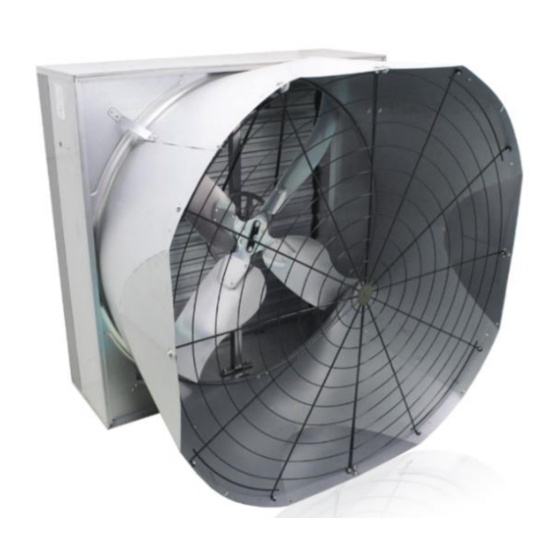
Exhaust fan
Hide thumbs
Also See for EC52:
- Manual for use and maintenance (45 pages) ,
- Assembly manual (44 pages) ,
- Manual for use and maintenance (56 pages)

Related Manuals for Munters EC52


Summary of Contents for Munters EC52
- Page 1 EC52 with Munters Drive Manual for use and maintenance + CE Declaration of conformity EC52 with Munters Drive Exhaust fan Ag/MIT/UmGB-2345-03/16 Rev. 1.1...
- Page 2 Munters Italy S.p.A. reserves the right to effect modifications to the apparatus in accordance with technical and legal developments and to make alterations to specifications, quantities, etc., for production or other reasons, subsequent to publication.
- Page 3 5.1 Assembly of the cone 5.2 Assembly of the gear motor 5.3 Placement of fans 5.4 Electrical wiring 5.5 Standard wiring between VFD, motor and juction box 5.6 Reversing Belimo actuator positioning COMMISSIONING TECHNICAL DATA 7.1 Dimensions 7.2 Technical specification © Munters AB, 2016...
- Page 4 Index MAINTENANCE 8.1 Introduction 8.2 Cleaning SPARE PART LIST WARRANTY © Munters AB, 2016...
-
Page 5: Ce Declaration Of Conformity
DECLARES ON ITS OWN RESPONSIBILITY THAT THE APPARATUS Exhaust fan designed for moving air to control temperature Designation and humidity in livestock. Model EC52 with Munters Drive Year of manufacture 2016 CONFORMS WITH THE ESSENTIAL SAFETY REQUIREMENTS STATED BY APPARATUS DIRECTIVE 2006/42/EC, 2004/108/EC, 2006/95/EC AND PERFORMANCE REQUIREMENTS COMPLY WITH THE ERP DIRECTIVE 2009/125/CE. -
Page 6: Attached Technical Documentation
The information contained herein has been prepared by qualified experts within Munters. While we believe the information is accurate and complete, we make no warranty or representation for any particular purposes. The information is offered in good faith and with the understanding that any use of the units or accessories in breach of the directions and warnings in this document is at the sole discretion and risk of the user. -
Page 7: Safety Aspects
Safety aspects The safety of fans is assured by Munters in compliance with the safety requirements indicated by the CE label. Safe functioning is assured only when the installation procedure and the instructions for use have been carefully followed. The following points must be stressed: •... -
Page 8: Before Using
(see section 5.1), turn the propeller by hand while the fan is switched off to verify smooth rotation of the propeller. 3.2 Packaging and transport of assembled fans The fan has a self-supporting structure in Munters Protect coated steel and it is delivered with packaging. fig.1 Once unpacked check the opening of the shutter manually by rotating the central shutter blade. - Page 9 The fans consist of the following components: • fan housing in Munters Protect coated steel without welding spots; • propeller with four blades in Munters Protect coated steel; blades are fixed to the propeller by high-strength pop rivets; • pyramidal shape and flat meshes for protection on back and front side;...
-
Page 10: Operating Conditions
Operating conditions Exhaust fans, such as the EC52 with Munters Drive, are products to be used to circulate the air inside a structure, thereby creating air movement inside the structure which helps to cool animals down during hot periods. Normal ambient temperature limits are –25°C to +50°C. Maximum altitude is 1000m above sea level. Should a fan be required to operate at a higher altitude, the loss in mass flow (heat removing capacity) due to lower air density should be taken into consideration. -
Page 11: Installation
5. Repeat from step 2, using the remaining two sectors, steering the fingers on the same side. 6. Close the cone steering the fingers internally. fig.7 © Munters AB, 2016... - Page 12 9. Draw half a mesh up to the cone’s border. fig.10 10. Bolt all the grommet to the sector. 11. Repeat from step 9 for the latter half a mesh. fig.11 12. Bind the semimeshes with the three (plus three) pliable tabs/flaps. fig.12 © Munters AB, 2016...
- Page 13 4 M8x16 screws (ref.45), plain washer (ref.43) and Ø8 ext thooted washer (ref.44). Taking care to tighten the gear motor (Belimo) on to the plastic arm, while the shutter is closed. fig.16 For the wiring see the following pages. © Munters AB, 2016...
-
Page 14: Placement Of Fans
Chapter5 Installation 5.3 Placement of fans The EC52 with Munters Drive is installed on a wall or structure and a free space NOTE at least of 2,500mm should be left open on inlet and outlet sides of the fan. Wall stucture fig.17... -
Page 15: Electrical Wiring
A network filter (type FIN3755.007.M), compulsory to comply with European EMC requirements and supplied by Munters upon request in a dedicate box, is also needed and must be wired upstream of the VFD. Moreover, a toroid, is already wired by Munters on the line between VFD and motor. - Page 16 0 (zero). The auxiliary signalization switch must be positioned at 3 o’clock when the actuator is fully rotated counterclockwise. The auxiliary signalization switch must be positioned at 9 o’clock when the actuator is fully rotated clockwise. fig.21 © Munters AB, 2016...
- Page 17 Installation To operate the Munters Drive Off/Variable speed with a 0-10V signal, slide the ‘ON’ switch, located on the circuit board in the junction box, away from the ‘ON’ position. Now wire the S2 command from the gear motor to the COMMOM command in the junction box and wire the S1 command from the gear motor to the RUN command in the junction box.
- Page 18 Failure to operate the fan with an overload protection device will render the motor guarantee null and void. Such motor overload protection devices can be NOTE ordered from Munters and be supplied with the fans. The excess of lenght of the connection cable must be completely extracted from WARNING the fan housing in order to avoid being damaged by moving parts.
- Page 19 Chapter5 Installation 5.5 Standard wiring between VFD, motor and junction box Junction box, DC motor and VFD are already wired by Munters. If, for some reason, wiring is unplugged follow the schemes. Power Terminal Block (line, VFD, Motor): R,S,T for input 3 phase...
- Page 20 In the junction box you have to change the connection from RUN - S1 and COMM - S2 to RUN - S1 and COMM - S3. After that, by removing the IP gear motor cover you have to switch the rotation selector from 0 (zero) to 1. © Munters AB, 2016...
- Page 21 Wait until the electrical power has been WARNING switched off and the fan has come to a complete stand still. Lock the electrical switch in the off position with a pad lock while working on the fan. © Munters AB, 2016...
-
Page 22: Technical Data
/h [cfm] 24,300 [14,300] 37,700 [22,200] 51,400 [30,200] Airflow at 25 Pa 2 /h [cfm] 15,200 [8,900] 34,600 [20,400] 49,400 [29,100] Specific performance at 12 Pa 2 /h /W [cfm /W] 81.2 [47.8] 49.9 [29.4] 30.6 [18.0] © Munters AB, 2016... - Page 23 1 Includes safety kit for installation below 2.7m above the floor. 2 All declared values are measured and certified by Bess Lab (test #16701). Airflow data are measured at standard conditions (20°C, 1,013 hPa). © Munters AB, 2016...
-
Page 24: Maintenance
In this particular event the manufacturer refuses all responsibility on consequent damages caused to things and people and considers any kind of warranty lost. © Munters AB, 2016... -
Page 25: Spare Part List
Spare part list EC52 with Munters Drive 28 29 fig.27 © Munters AB, 2016... - Page 26 45 47 fig.28 VIEW B - ELECTRICAL BOX fig.29 Spare parts Ref. Description Quantity EC52 WITH MUNTERS DRIVE LOWER SAFETY MESH M06 HEX NUT THICK PLASTIC TIE LEGRAND MM9X357 UPPER SAFETY MESH Ø6×24 WASHER M06X16 HEX SCREW CONE SECTOR CUT CONE SECTOR NORMAL Ø6,3×19 SELF-TAPPING SCREW...
- Page 27 Chapter9 Spare part list TOP PANEL COVER PLATE EC52 MD CONVEYOR COVER PLATE EXT TOOTHED WASHER D10,5X18 M10 HEX NUT OVAL PLATE M10×30 SCREW PLAIN WASHER D10X40 MUNTERS DRIVE MOTOR TOROID PLASTIC TIE ROD STOP COLLAR RIGHT BEARING FOR EC SERIES...
- Page 28 M04×16 HEX SCREW EUROEMME STICKER 24.6X180 ® WARNING STICKER A-1997 35X210 WARNING STICKER B-1997 70X105 PRODUCT LABEL G-1998 95X115 NO HIGH PRESSURE STICKER 42X118 MUNTERS PROTECT STICKER 70X46 QUALITY CHECK LABELS *References not appearing in the exploded view. © Munters AB, 2016...
-
Page 29: Warranty And Technical Assistance
Munters plant was required: if this is not done, the user is fully responsible for the damage which they could suffer. - Page 30 Requests for technical assistance and spare parts must be made directly to the manufacturer, at the following address: Munters Italy S.p.A Strada Piani, 2 18027 Chiusavecchia (IM), Italy Tel: +39 0183 52 11 Fax: +39 0183 521 333 info@munters.it © Munters AB, 2016...
- Page 31 Euroemme EC52 with Munters Drive extraction fan is developed and produced by Munters Italy S.p.A., Italy ® www.munters.com Australia Phone +61 2 8843 1594, agh.info@munters.com.au, Brazil Phone +55 41 3317 5050, contato@munters.com, Canada Phone +1 517 676 7070, aghort.info@munters.com, China Phone +86 10 8048 3493, marketing@munters.cn,...
-
Page 32: Technical Data Sheet
Technical data sheet NM230P-S RobustLine damper actuator for adjusting dampers in industrial plants and in technical building installations • Damper size up to approx. 2 m² • Nominal torque 10 Nm • Nominal voltage AC 230 V • Control: Open-close, 3-point • With integrated auxiliary switch • Optimum protection against corrosion and chemical influences, UV radiation, moisture and condensation Technical data Electrical data Nominal voltage AC 230 V Nominal voltage frequency 50/60 Hz Nominal voltage range... -
Page 33: Product Features
Damper actuator, IP66 + IP67, open-close, 3-point, NM230P-S AC 230 V, 10 Nm, with integrated auxiliary switch Safety notes • The cable must not be removed from the device. • When calculating the torque required, the specifications supplied by the damper manufacturers (cross-section, construction, place of installation), and the ventilation conditions must be observed. • The device contains electrical and electronic components and is not allowed to be disposed of as household refuse. All locally valid regulations and requirements must be observed. • The information on chemical resistance refers to laboratory tests with raw materials and finished products and to trials in the field in the fields of application indicated. • The materials used may be subjected to external influences (temperature, pressure, constructional fastening, effect of chemical substances etc.) that cannot be simulated in laboratory tests or field trials. -
Page 34: Electrical Installation
Damper actuator, IP66 + IP67, open-close, 3-point, NM230P-S AC 230 V, 10 Nm, with integrated auxiliary switch Electrical installation Notes • Caution: Power supply voltage! • Parallel connection of other actuators possible. Observe the performance data. Wiring diagrams AC 100 ... 240V, open-close Cable colours: 1 = blue S1 S2 S3 2 = brown 3 = white S1 = violet S2 = red 0...100% S3 = white AC 100 ... 240V, 3-point Cable colours: 1 = blue S1 S2 S3 2 = brown 3 = white... -
Page 35: Dimensions (Mm)
Damper actuator, IP66 + IP67, open-close, 3-point, NM230P-S AC 230 V, 10 Nm, with integrated auxiliary switch Dimensions [mm] Spindle length Dimensional drawings ~271 20 ... 58 Clamping range 10 ... 20 mm 8 ... 14 mm ∅ 5.3 10 ... 20 mm NM230P-S • en-gb • 2013-02-21 • Subject to modification www.belimo.com...
Need help?
Do you have a question about the EC52 and is the answer not in the manual?
Questions and answers