
Related Manuals for Munters WF54


Summary of Contents for Munters WF54
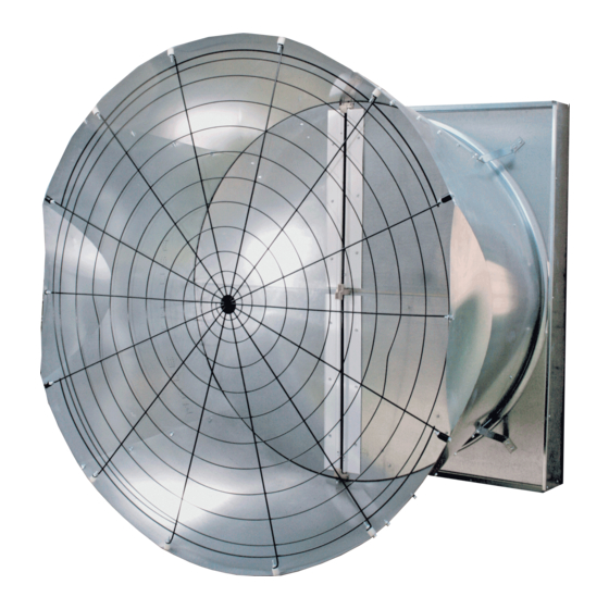
- Page 1 WF54 54” Tilt Fan with Munters Drive* Instruction Manual *Patents Pending WF54 Tilt Wall Fan with Munters Drive 54” Tilt Wall Exhaust Fan dels: WF54DTxxCXP-Hx • WF54DTxxCXJ-Hx © Munters Corporation, March 2017 QM1224r3...
-
Page 2: Thank You
Manual for use and Maintenance Thank You: Thank you for purchasing a Munters WF54 tilt fan with Munters Drive. Munters equipment is designed to be the highest performing, highest quality equipment you can buy. With the proper installation and maintenance it will provide many years of service. -
Page 3: Table Of Contents
2. Installation Instructions Fan Installation Shutter Installation 3. Electrical Wiring Recommended Wire Routing Electrical Wiring 4. Operation and Maintenance Operation Maintenenace 5. Troubleshooting Winterizing Winterizing Winter Weather Protection 7. Exploded View and Parts List © Munters Corporation, March 2017 QM1224r3... - Page 4 [G]..10 - ¾” O.D. x 1”L. Spacers Discharge cone is designed to mount on fan outlet for increased airflow and to support the NOTE: exhaust guard. A shutter or guard must be mounted on the fan inlet. © Munters Corporation , March 2017 QM1224r3...
-
Page 5: Fan Dimensions
Dimensions: Cat. No. Cone Type Wall Openings Below F.O. Cone Height Cone Width (W.O.) WF54 54GCX ⁄ ” ⁄ ” ⁄ ” 56” 58” ⁄ ” 66” 59” ⁄ ”W. x 62 ⁄ ”H. © Munters Corporation, March 2017 QM1224r3... -
Page 6: Installation Instructions
Concrete Framing Framing cut at 12° to match fan housing 2 x 4 framing Concrete framing Catalog No. WF54 56½"W. x 62½"H. 56½"W. x 64"H. Chart A Figure 1D Greater than 4” Wall Thickness © Munters Corporation , March 2017 QM1224r3... - Page 7 This is NOT the Wall Opening size. ⁄ ” 56” Figure 3B Figure 4A Step 6 Make electrical connections to fan motor per instructions provided with fan or as shown on motor. See Wiring Section on page 9. © Munters Corporation, March 2017 QM1224r3...
-
Page 8: Shutter Installation
See Figure 5A. Fasten shutter in place by rotating the side and top shutter clips over the shutter flanges, See Figure Shutter Clip Side Shutter Clip Bottom Shutter Clip Figure 5B Figure 5A © Munters Corporation , March 2017 QM1224r3... -
Page 9: Electrical Wiring
3.1 Recommended Wire Routing Option 1 - Step 1 The Munters Drive fan comes with a coil of electrical cables that is pre-wired to the motor. Find the end of the cable and form a drip loop and then run the cable... -
Page 10: Electrical Wiring
Fans used to ventilate livestock buildings or other rooms where continuous air movement is essential should be connected to individual electrical circuits, with a minimum of two circuits per room. Single Phase and Three Phase Munters Drives: Power supply for fans to have Circuit Breaker High Voltage, disconnect power before servicing. - Page 11 See Figure 9A . To operate the Munters Drive On/Off with a control, Slide the ‘ON’ switch, located on the circuit board in the junction box, away from the ON position. Now wire an ‘ON’ command from the ‘COMMON’ terminal to the input relay in the control and from the output of the control relay to the ‘RUN’...
- Page 12 Chapter 3 Electrical Wiring ‘ON’ Switch Junction Box Junction Box 10-0V Figure 9B Output Off/Low/High Remotely In Control © Munters Corporation , March 2017 QM1224r3...
- Page 13 Chapter 3 Electrical Wiring To operate the Munters Drive Off/Low/High with a control, slide the ‘ON’ switch, located on the circuit board in the junction box, away from the ON position. Now wire an ‘ON’ command from the “COMMOM” terminal to the input relay in the control and from the output of the relay to the ‘RUN’...
- Page 14 Chapter 3 Electrical Wiring ‘ON’ Switch Junction Box 10-0V Output In Control Junction Box Figure 9D Variable Speed Operation © Munters Corporation , March 2017 QM1224r3...
- Page 15 Chapter 3 Electrical Wiring To operate the Munters Drive Off/Variable with a 10-0V Signel, slide the ‘ON’ switch, located on the circuit board in the junction box, away from the ON position. Now wire an ‘ON’ command from the ‘COMMON’...
-
Page 16: Operation And Maintenance
With power disconnected, inspect all electrical connec- tions. Wiring should be secure and in good condition. Remove any dust build-up from control case and sensor using a soft brush or cloth. NEVER CLEAN ELECTRICAL EQUIPMENT WITH A PRESSURE WASHER! © Munters Corporation , March 2017 QM1224r3... -
Page 17: Troubleshooting
3. Verify Prop turns freely an 'On' command is present. a. If not contact Munters Product Support b. If it turns freely go to next step 4. Turn AC power back on to fan a. -
Page 18: Winterizing
The supplier listing above is given Warranties do not cover cone or fan as a reference only. Aerotech does not endorse any specific snow guard product and no performance warranty is implied. damage from external sources. © Munters Corporation , March 2017 QM1224r3... -
Page 19: Exploded View And Parts List
Exploded View © Munters Corporation, March 2017 QM1224r3... - Page 20 WF54 Tilt Fan with Munters Drive is developed and produced by Munters Corporation, Lansing, Michigan U.S.A. 1-800-227-2376 Munters Europe AB, Isafjordsgatan 1, P.O. Box 1150, SE-164 26 Kista, Sweden. Phone +46 08 626 63 00, Fax +46 8 754 56 66.
Need help?
Do you have a question about the WF54 and is the answer not in the manual?
Questions and answers