
Subscribe to Our Youtube Channel
Related Manuals for Munters ATLAS 74


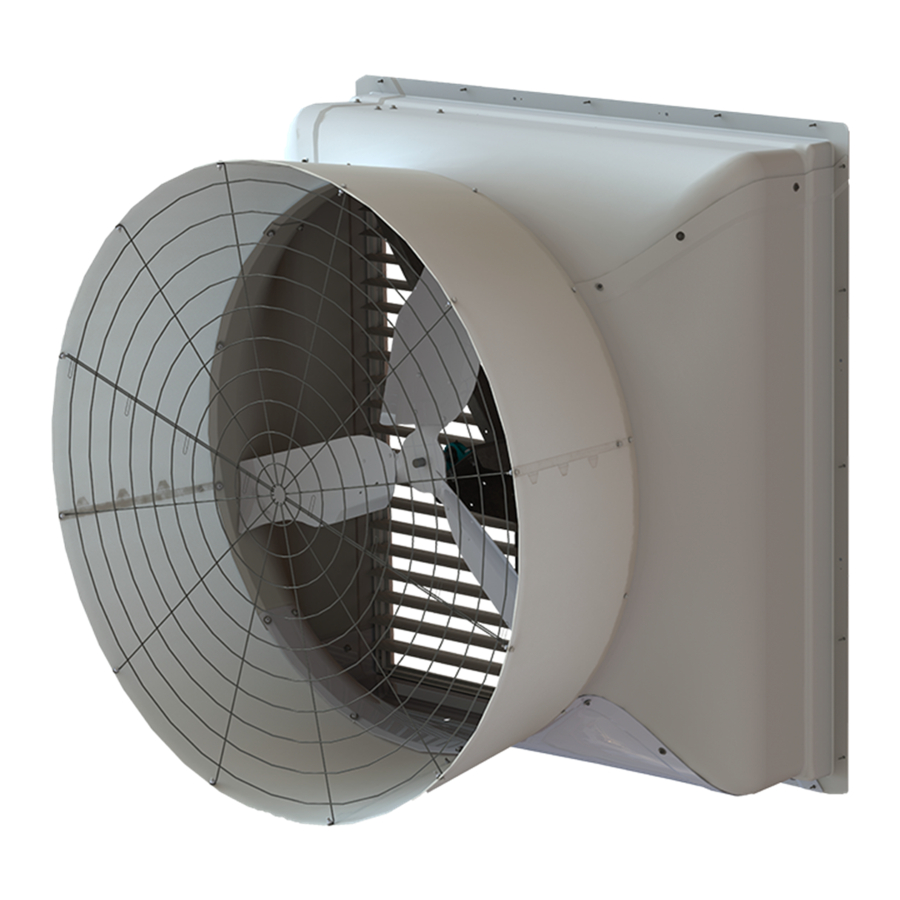
Summary of Contents for Munters ATLAS 74
- Page 1 ATLAS 74 74” Exhaust Fan Instruction Manual with Munters Drive* ¡ ¢ £ ¤ ¥ £ ¦ ¡ ¤ ¥ § ¨ ¥ © ATLAS 74 Fan with Munters Drive Models: ATS74D3F43CT-HO • ATS74D3F43CT-HE © Munters Corporation, November 2023 QM1495r1...
-
Page 2: Warranty
Instructions for Use and Maintenance Thank You: Thank you for purchasing an ATLAS 74 Fan with Munters Drive. Munters equipment is designed to be the highest performing, highest quality equipment you can buy. With the proper installation and maintenance it will provide many years of service. - Page 3 Fan Operation Off /Variable with 10-0V Signal Fan Operation Off /Variable with Potentiometer Fan Alarm Connections 4. Operation and Maintenance 5. Troubleshooting 6. Winterizing Winterizing Winter Weather Protection 7. Exploded View and Parts List 28-29 © Munters Corporation, November 2023 QM1495r1...
-
Page 4: Unpacking The Equipment
A Munters Lift Kit, FH1890, is required for installation of Atlas Fan. One Lift Kit may be used for multiple Atlas Fans. Failure to use the Munters Lift Kit may result in damage to fan. DO NOT use chains to lift fan for installation. Damage from chains will not be covered under warranty. - Page 5 SIDE VIEW FRONT VIEW WALL OPENING K-Dia. DIA. (I.D., framed) 74” ⁄ ” 21 ⁄ ” 44 ⁄ ” 89” 89” ⁄ ” 35 ⁄ ” 60 ” 2⁵⁄₁₆” ⁄ ” 84½ ”W. 84½ ”H. © Munters Corporation, November 2023 QM1495r1...
- Page 6 Wind Kit Brackets adjacent to each other, the minimum fan spacing is 98" Center-to-Center. See Figure Below. 98" Center-to-Center Top View (Recommended Fan Spacing) 98" Center-to-Center 3¾ " ¼ " Elevation View (Recommended Fan Spacing) © Munters Corporation, November 2023 QM1495r1...
- Page 7 If the fans are to be installed closer, then the Wind Kit Bracket for one fan should be offset 6" up or down from the previous fan, then the minimum fan spacing is 93" Center-to-Center. See Figure Below. 93" Center-to-Center Top View 93" Center-to-Center 3¾ " ¼ " Elevation View © Munters Corporation, November 2023 QM1495r1...
-
Page 8: Installation Instructions
Page 5) Concrete Stem Wall Building Columns - 20’-0” O.C. Figure 1A Building Column 4x4 Post or 2x Treated Framing (See Chart on Page 5) Concrete Stem Wall Building Columns - 25’-0” O.C. Figure 1B © Munters Corporation, November 2023 QM1495r1... - Page 9 Figure 1C WARNING: A Munters Lift Kit, FH1890, is required for installation of Atlas Fan. One Lift Kit may be used for multiple Atlas Fans. Failure to use the Munters Lift Kit may result in damage to fan. DO NOT use chains to lift fan for installation.
- Page 10 Installation Instructions Step 3A Using Munters Lift Kit, FH1890, insert fan into the framed opening from the inside. While holding fan tight to framing, fasten top of fan with (5) ¼ " x 1.5"L. minimum Mounting Screw/Bolt (not provided). See Figure 3A .
- Page 11 End Flanges together using (1) Bolt [D] and Nylock Nut [E]. See Figure 5. Do not fully tighten the last bolt and nut at this time. Bolt [D] End Flange Nylock Nut [E] Figure 5 © Munters Corporation, November 2023 QM1495r1...
-
Page 12: Cone Installation
At the inner pair of holes of each joint fasten using (1) Bolt [A] and Nut [B] with the bolt head on the side with the tabs. See Figure 7. Nut [B] Bolt [A] Outer Hole Bolt [A] Inner Hole Nut [B] Figure 7 © Munters Corporation, November 2023 QM1495r1... - Page 13 Torque the last Ring Bolt to 125 in-lbs [14 Nm], and then tighten all the cone bolts at this time. Slot in Tab lined up with Hole in Fan Orifi ce Nut [B] Washer [C] Bolt [A] Figure 9 © Munters Corporation, November 2023 QM1495r1...
- Page 14 Insert guard into cone with the eyelets facing you. Install eyelets over (4) Bolts already installed at joints in cone and fasten with Nut [B]. Secure (8) remaining eyelets using Bolt [A] and Nut [B]. See Figure 11. Bolt [A] Nut [B] Previously installed - Bolt and Nut Nut [B] Figure 11 © Munters Corporation, November 2023 QM1495r1...
- Page 15 Step 13 Fasten shutter in place by rotating the side and top shutter clips over the shutter flanges. See Figure 13. ¼ " Position to install/remove Shutter Figure 13 Position to hold Shutter in place © Munters Corporation, November 2023 QM1495r1...
- Page 16 'U' slot should be facing up and each Bracket should be mounted in same direction. See Figure 14A. Fasten Brackets in place using (2) Lag Screws (not provided). See Figure 14B. Figure 14A Wind Kit Bracket Lag Screw (not provided) Figure 14B © Munters Corporation, November 2023 QM1495r1...
- Page 17 Slide the Wind Kit Pipe into the hole in the Left Wind Kit Bracket until it stops at the other side of the Bracket and set Pipe down into slot in opposite Bracket. See Figure 15A. For the completed Wind Kit installation See Figure 15B. Figure 15A Figure 15B © Munters Corporation, November 2023 QM1495r1...
-
Page 18: Electrical Wiring
For electrical connection requirements, refer to diagram on motor nameplate and to information enclosed with the Munters environmental control to be used. After wiring check for proper motor rotation. -
Page 19: Recommended Wire Routing
3.1 Recommended Wire Routing: As the power cable exits the Munters Drive Box form a drip loop and then run power cable down along strut and "Zip" tie the cable to strut to prevent cable from getting tangled in the propeller. - Page 20 3.2 Three Phase Power connection: All cables that enter the Munter Drive box must enter through a properly sized watertight fitting. Loosen the (4) screws in the cover of the Munters Drive box to access the terminals inside to connect power and other cables.
- Page 21 To operate the fan On/Off with a control, wire an 'ON' command from the'SN' terminal to the input relay in the control and from the output of the control relay to the 'S1' terminal. See Figure 20. Do not remove the Factory Installed Jumpers. Figure 20 © Munters Corporation, November 2023 QM1495r1...
- Page 22 ‘S1’ terminal. Then connect wires from the 10-0V output in the control to the 'A1' and 'AC' terminals in the Munters Drive Box. The '+' output in the control shoud go to 'A1' and the ' - ' output should go to 'AC'.
-
Page 23: Alarm Connections
Potentiometer Figure 23 3.8 Alarm Connections The Munters Drive uses a Normally Closed circuit for alarm connections. To connect a control to the Normally Closed output make appropriate connecions from the control to ‘MB’ and ‘MC’ terminals. See Figure 24. -
Page 24: Operation And Maintenance
With power disconnected, inspect all electrical connections. Wiring should be secure and in good condition. Remove any dust build-up from control case and sensor using a soft brush or cloth. NEVER CLEAN ELECTRICAL EQUIPMENT WITH A PRESSURE WASHER! © Munters Corporation, November 2023 QM1495r1... -
Page 25: Troubleshooting
3. Verify Prop turns freely an 'On' command is present. a. If not contact Munters Product Support b. If it turns freely go to next step 4. Turn AC power back on to fan a. -
Page 26: Winter Weather Protection
Munters Product and System manufacturers recommendations. The supplier listing above is given Warranties do not cover cone or fan as a reference only. Munters does not endorse any specific snow guard product and no performance warranty is implied. damage from external sources. - Page 27 This page left blank intentionally © Munters Corporation, November 2023 QM1495r1...
-
Page 28: Exploded View
Exploded View © Munters Corporation, November 2023 QM1495r1... - Page 29 Fixed Shutter clip, PL PT74 PT74 Shutter, all plastic FA2619 FA2619 Wind Bracket, GZ AC1416 AC1416 Wind Pipe, GZ FH2890 FH2890 Reinforcing Ring, 1/4 Section, Atlas74, PWDCTD, WHT HP1162 HP1162 Hardware Pkg., Fan/Cone Install © Munters Corporation, November 2023 QM1495r1...
- Page 30 Atlas 74 Fan with Munters Drive is developed and produced by Munters Corporation, Lansing, Michigan U.S.A. 1-800-227-2376 Munters Europe AB, Isafjordsgatan 1, P.O. Box 1150, SE-164 26 Kista, Sweden. Phone +46 08 626 63 00, Fax +46 8 754 56 66.
Need help?
Do you have a question about the ATLAS 74 and is the answer not in the manual?
Questions and answers