Table of Contents
Advertisement
Quick Links
Aerotech
CX Series
Circulation Fan
Instruction Manual
with
74" Fan
Munters Drive*
¡
¢
£
¤
¥
£
¦
¡
¤
¥
§
¨
¥
©
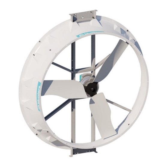
CX74 Munters Drive Front View
CX74 Munters Drive Rear View
CX74 Fan with Munters Drive
Models: CX74D3F43-HO-1PK • CX74D3F43-HO-2PK •
CX74D3F43-HO-3PK
© Munters Corporation, August 2023
1
QM1243r0
Advertisement
Table of Contents

Related Manuals for Munters CX Series


Summary of Contents for Munters CX Series
- Page 1 ¢ £ ¤ ¥ £ ¦ ¡ ¤ ¥ § ¨ ¥ © CX74 Munters Drive Front View CX74 Munters Drive Rear View CX74 Fan with Munters Drive Models: CX74D3F43-HO-1PK • CX74D3F43-HO-2PK • CX74D3F43-HO-3PK © Munters Corporation, August 2023 QM1243r0...
- Page 2 Please Note: To achieve maximum performance and ensure long life from your Munters product it is essential that it be installed and maintained properly. Please read all instructions carefully before beginning installation. Warranty: For Warranty claims information see the “Warranty Claims and Return Policy”...
- Page 3 Unpacking the Equipment Parts List Fan Dimensions 2. Electrical Wiring Recommended Wire Routing Determining Drive Type for wiring V1000 Drive Wiring GA500 Drive Wiring 3. Operation and Maintenance 4. Troubleshooting 5. Exploded View and Parts List © Munters Corporation, August 2023 QM1243r0...
-
Page 4: Unpacking The Equipment
Any shipping damage is the customer’s responsibility and should be reported immediately to your freight carrier. 1.1 Parts List 1.2 Fan Dimensions Each Fan includes: Fan Specifi cations: 1 – Munters Drive Fan Hertz: Voltage: 460VAC Phase: Weight: 400 lbs. [182 Kg] 17⅜... -
Page 5: Electrical Wiring
For electrical connection requirements, refer to diagram on motor nameplate and to information enclosed with the Munters environmental control to be used. After wiring check for proper motor rotation. - Page 6 2.1 Recommended Wire Routing: As the power cable exits the Munters Drive Box form a drip loop and then run power cable up along strut and "Zip" tie the cable to strut to prevent cable from getting tangled in the propeller.
- Page 7 Chapter 2 Electrical Wiring 2.2 Determining Drive type for wiring To access the Drive, loosen the (4) screws in the cover of the Munters Drive box to access the terminals inside to connect power and other cables. See Figure 2A.
- Page 8 Electrical Wiring 2.3 V1000 Drive Wiring Three Phase Power connection: Run the 3 phase power cable through watertight fitting into the Munters Drive box and connect to the terminals "R/L1, S/L2, T/L3" and Ground in the box. See Figure 3.
- Page 9 Then connect a wire from ‘S1’ terminal to the output side of the 'ON' relay and then connect a wire from the ‘S7’ terminal to the ouput side of the ‘LOW’ relay. See Figure 6. Do not remove the Factory Installed Jumper. ‘LOW’ Relay ‘ON’ Relay Figure 6 © Munters Corporation, August 2023 QM1243r0...
- Page 10 ‘S1’ terminal. Then connect wires from the 10-0V output in the control to the 'A1' and 'AC' terminals in the Munters Drive Box. The '+' output in the control shoud go to 'A1' and the ' - ' output should go to 'AC'.
- Page 11 Electrical Wiring Alarm Connections - V1000 The Munters Drive uses a Normally Closed circuit for alarm connections. To connect a control to the Normally Closed output make appropriate connecions from the control to 'MB' and 'MC' terminals. See Figure 9.
- Page 12 Electrical Wiring 2.4 GA500 Drive Wiring Three Phase Power connection: Run the 3 phase power cable through watertight fitting into the Munters Drive box and connect to the terminals "R/L1, S/L2, T/L3" and Ground in the box. See Figure 10.
- Page 13 Then connect a wire from ‘S1’ terminal to the output side of the ‘ON’ relay and then connect a wire from the ‘S7’ terminal to the ouput side of the ‘LOW’ relay. See Figure 13. Do not remove the Factory Installed Jumper. ‘LOW’ Relay ‘ON’ Relay Figure 13 © Munters Corporation, August 2023 QM1243r0...
- Page 14 ‘S1’ terminal. Then connect wires from the 10-0V output in the control to the 'A1' and 'AC' terminals in the Munters Drive Box. The '+' output in the control shoud go to 'A1' and the ' - ' output should go to 'AC'.
- Page 15 ‘SN’ terminal. Then connect wires from the Modbus output in control to the 'D+', 'D-' and 'AC' terminals and the 'S2' terminal if required in the Munters Drive Box.
-
Page 16: Operation And Maintenance
With power disconnected, inspect all electrical connections. Wiring should be secure and in good condition. Remove any dust build-up from control case and sensor using a soft brush or cloth. NEVER CLEAN ELECTRICAL EQUIPMENT WITH A PRESSURE WASHER! © Munters Corporation, August 2023 QM1243r0... -
Page 17: Troubleshooting
3. Verify Prop turns freely an 'On' command is present. a. If not contact Munters Product Support b. If it turns freely go to next step 4. Turn AC power back on to fan a. -
Page 18: Exploded View
Hub, Prop Adapter, 1.188”D. x 2.875”L., w/ Keyway, ZP FM1466-CX74HO Assembly, Motor and Drive, Prgmd, CX74, 460V FH2574 Bracket, Spacer, MD G2 Max, CX74 Fan, GZ FH2573 Bracket, Mounting, MD G2 Max, CX74 Fan, CTD-STEEL, BLK © Munters Corporation, August 2023 QM1243r0... - Page 19 This page left blank intentionally © Munters Corporation, August 2023 QM1243r0...
- Page 20 CX74 Circulation Fan with Munters Drive is developed and produced by Munters Corporation, Lansing, Michigan U.S.A. 1-800-227-2376 Munters Europe AB, Isafjordsgatan 1, P.O. Box 1150, SE-164 26 Kista, Sweden. Phone +46 08 626 63 00, Fax +46 8 754 56 66.
Need help?
Do you have a question about the CX Series and is the answer not in the manual?
Questions and answers