
Related Manuals for PI V-417.136211E1 PIMAG


Summary of Contents for PI V-417.136211E1 PIMAG
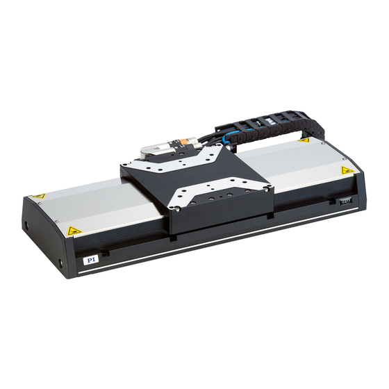
- Page 1 V417M0002EN ‒ 11/16/2018 User Manual V-417.136211E1 PIMAG® LINEAR STAGE M O T I O N | P O S I T I O N I N G...
-
Page 2: Table Of Contents
CONTENTS V417M0002EN ‒ 11/16/2018 Contents Legal Information......................4 About this Document....................5 Objective and Target Group................5 Explanation of Symbols..................5 2.2.1 Typographic Conventions..............5 2.2.2 Symbols Used..................5 Figures........................ 6 Downloading Manuals..................6 Safety..........................7 Intended Use...................... 7 General Safety Instructions................7 Organizational Measures.................. - Page 3 CONTENTS V417M0002EN ‒ 11/16/2018 12 Technical Data......................26 12.1 Specifications....................26 12.2 Maximum Ratings................... 28 12.3 Ambient Conditions and Classifications............28 12.4 Dimensions...................... 30 13 Old Equipment Disposal................... 32 14 Appendix........................34 14.1 Pin Assignment....................34 14.1.1 Drive connector................34 14.1.2 Encoder connector................34 14.2 Drive properties....................35 14.3 Reference point switch specifications............35 14.4 Limit Switch Specifications................35 14.5 NTC temperature sensor.................36...
-
Page 4: Legal Information
With regard thereto, Physik Instrumente (PI) GmbH & Co. KG reserves all rights. The use of any text, images and drawings is permitted only in part and only when indicating the source. -
Page 5: About This Document
This user manual contains the information needed for the intended use of the V-417.136211E1. Basic knowledge of closed-loop systems, motion control concepts, and applicable safety measures is assumed. Explanation of Symbols This chapter explains the symbols and markings used by PI in their user manuals. 2.2.1 Typographic Conventions Symbol / Label Meaning... -
Page 6: Figures
(p. 25). Downloading Manuals 1. Open the website www.pi.ws. 2. If the product was shipped with a data storage device: Log into the website: a) Click Login. b) Enter the login data. The login data is in the [...]_Releasenews_[...].pdf in the Manuals directory on the data storage device. -
Page 7: Safety
► Always keep this user manual available with the V-417.136211E1. The latest versions of the user manuals can be downloaded (p. 6) at www.pi.ws. ► Add all information from the manufacturer such as supplements or technical notes to the user manual. -
Page 8: Product Description
4 PRODUCT DESCRIPTION V417M0002EN ‒ 11/16/2018 Product Description Product Labeling Figure 1: Product label on the V-417.136211E1 1. Warning symbol: Risk of crushing 2. Type plate 3. Connector labels 4. Warning symbol: Electrostatic-sensitive device 5. Optional protective earth connector 6. Functional earth 4.1.1 Type Plate Figure 2: Type plate of the V-417.136211E1... -
Page 9: Scope Of Delivery
4 PRODUCT DESCRIPTION V417M0002EN ‒ 11/16/2018 Scope of Delivery Product number Description V-417.136211E1 Linear stage according to order V417B0015 Mounting kit for mounting the V-417.136211E1, consisting of ■ 12 socket head screws, ISO 4762 M6×30 ■ 2 dowel pins, ISO 8734, 4m6 × 12 000036450 M4 screw set for protective earth, consisting ■... -
Page 10: Suitable Electronics
4 PRODUCT DESCRIPTION V417M0002EN ‒ 11/16/2018 Reference Point Switch The reference point switch is a sensor whose fixed position serves as the reference point for incremental sensor signals. Position sensor The sensor measures the position of the motion platform incremental to a known reference point. -
Page 11: Unpacking
5 UNPACKING V417M0002EN ‒ 11/16/2018 Unpacking Figure 3: V-417.136211E1 with transport safeguard 1. Transport safeguard 2. Wing screw CAUTION Risk of crushing by moving parts! Risk of minor injuries from crushing between the moving parts of the V-417.136211E1 or the load and a fixed part or obstacle. -
Page 12: Installation
6 INSTALLATION V417M0002EN ‒ 11/16/2018 Installation Mounting the V-417.136211E1 Overview Tools and Accessories Screw set for mounting the V-417.136211E1 (p. 9) ■ ■ Suitable screwdriver Requirements You have read and understood the general safety instructions (p. ✓ You have provided a suitable surface with the holes necessary for the screws and if ✓... -
Page 13: Connecting The V-417.136211E1 To The Protective Earth Conductor
6 INSTALLATION V417M0002EN ‒ 11/16/2018 CAUTION Risk of crushing by moving parts! Risk of minor injuries from crushing between the moving parts of the V-417.136211E1 or the load and a fixed part or obstacle. ► Use safeguards to protect limbs areas where they could be caught by moving parts. ►... - Page 14 6 INSTALLATION V417M0002EN ‒ 11/16/2018 Overview 1. Connector for the protective earth conductor on the V-417.136211E1, indicated by the protective earth symbol 2. Safety washer 3. Flat washer 4. Protective earth conductor lug 5. Screw, ISO 7045 M4×8 Tools and Accessories ■...
-
Page 15: Building A Multi-Axis System
6 INSTALLATION V417M0002EN ‒ 11/16/2018 4. Make sure that the contact resistance is <0.1 Ω at 25 A at all connection points relevant for attaching the protective earth conductor. Building a Multi-Axis System The V-417.136211E1 can be used in XY systems. Designations in these instructions: ■... - Page 16 6 INSTALLATION V417M0002EN ‒ 11/16/2018 3. Mount the upper V-417 onto the lower V-417. a) Insert two 4 mm h7 × 12 mm locating pins into the motion platform of the lower V-417. b) Align the upper V-417 to the lower V-417. c) If necessary: Push the motion platform of the upper V-417 to access the mounting holes in the base body.
- Page 17 6 INSTALLATION V417M0002EN ‒ 11/16/2018 e) Push the motion platform of the upper V-417 to the negative end of the travel range. f) Push the retaining plate under the drag chain. Align the retaining plate to the mounting hole of the upper V-417. g) Insert two M6×30 screws into the mounting holes in the upper V-417 and tighten them.
-
Page 18: Mounting The Load Onto The V-417.136211E1
6 INSTALLATION V417M0002EN ‒ 11/16/2018 Mounting the Load onto the V-417.136211E1 Overview Figure 4: Mount the load on the V-417.136211E1 1. Screws 2. Load 3. Motion platform of the V-417.136211E1 Tools and Accessories ■ At least 3 screws with suitable dimensions (p. -
Page 19: Connecting The V-417.136211E1
► Connect the V-417.136211E1 to suitable electronics (p. 10) from PI miCos only. ► Use cables from PI miCos only to connect the V-417.136211E1 to the electronics. Connecting the V-417.136211E1 1. If necessary: Remove the ESD protective caps from the connectors of the V-417.136211E1. -
Page 20: Startup / Operation
7 STARTUP / OPERATION V417M0002EN ‒ 11/16/2018 Startup / Operation Starting and Operating the V-417.136211E1 Requirements You have read and understood the general safety instructions (p. ✓ For startup with a load or in a multi-axis system: You have installed the V-417.136211E1 ✓... - Page 21 1. Start the electronics (see the user manual for the electronics). 2. Configure the electronics for the positioner during startup: ■ If you are using a digital controller from PI: In the PC software, select the entry in the positioner database that matches the positioner exactly.
-
Page 22: Maintenance
8 MAINTENANCE V417M0002EN ‒ 11/16/2018 Maintenance NOTICE Damage due to improper maintenance! Improper maintenance can lead to misalignment and failure of the V-417.136211E1. ► Loosen screws only according to the instructions in this manual or the instructions of our customer service department (p. 25). -
Page 23: Troubleshooting
9 TROUBLESHOOTING V417M0002EN ‒ 11/16/2018 Troubleshooting The positioner does not move, no operating noise can be heard There is a motion error. ► Reset the motion error. Defective electronics ► Check the electronics. Check all connecting cables (p. 19). Electronics not connected correctly ►... -
Page 24: Transportation
10 TRANSPORTATION V417M0002EN ‒ 11/16/2018 Transportation Preparing the V-417.136211E1 for Transportation 1. Pay attention to the ambient conditions and classifications (p. 28). 2. Pack the V-417.136211E1 in the original packaging. 3. If the V-417.136211E1 is to be sent, use a stable outer box. M O T I O N | P O S I T I O N I N G... -
Page 25: Customer Service Department
V417M0002EN ‒ 11/16/2018 Customer Service Department For enquiries and orders, contact your PI miCos representative or send us an email. If you have any questions concerning your system, provide the following information: ■ Product and serial numbers of all products in the system ■... -
Page 26: Technical Data
12 TECHNICAL DATA V417M0002EN ‒ 11/16/2018 Technical Data 12.1 Specifications Motion V-417.05 V-417.09 V-417.13 V-417.17 Unit Toler- ance Active axes Travel range Pitch / yaw ±14 ±19 ±29 ±39 μrad max. Straightness / flat- ±2.5 ±4 ±6 ±8 μm max. ness Velocity, unloaded 2000... - Page 27 12 TECHNICAL DATA V417M0002EN ‒ 11/16/2018 Mechanical properties V-417.xxxxxx Unit Toler- ance Guide type Recirculating ball bearing guide Load capacity in Z max. Permissible lateral force max. Permissible torque in θ N·m max. Permissible torque in θ N·m max. Permissible torque in θ N·m max.
-
Page 28: Maximum Ratings
12 TECHNICAL DATA V417M0002EN ‒ 11/16/2018 Miscellaneous V-417 Unit Toler- ance Material Aluminum, black anodized stainless steel Overall mass V-417.05 (102 mm travel range): 9.3 ±5 % V-417.09 (204 mm travel range): 11.2 V-417.13 (305 mm travel range): 13.0 V-417.17 (407 mm travel range): 14.8 V-417.21 (508 mm travel range): 16.6 V-417.25 (610 mm travel range): 18.4 V-417.33 (813 mm travel range): 21.1... - Page 29 12 TECHNICAL DATA V417M0002EN ‒ 11/16/2018 Area of application For indoor use only Maximum altitude 2000 m above msl Operating temperature 5 to 40 °C Storage temperature -20 °C to 60 °C Transport temperature -20 °C to 60 °C Overvoltage category Supply voltage fluctuations Max.
-
Page 30: Dimensions
12 TECHNICAL DATA V417M0002EN ‒ 11/16/2018 12.4 Dimensions Figure 5: Dimensions of the V-417.136211E1 Dimensions in mm. Note that the decimal places are separated by a comma in the drawings. M O T I O N | P O S I T I O N I N G... - Page 31 12 TECHNICAL DATA V417M0002EN ‒ 11/16/2018 Figure 6: Mounting holes in the V-417.136211E1's motion platform Dimensions in mm. Note that the decimal places are separated by a comma in the drawings. M O T I O N | P O S I T I O N I N G...
-
Page 32: Old Equipment Disposal
In order to fulfil the responsibility as the product manufacturer, PI miCos undertakes environmentally correct disposal of all PI miCos equipment free of charge, if it was made available to the market after August 13, 2005. Any old PI miCos equipment can be sent free of charge to the following address:... - Page 33 V417M0002EN ‒ 11/16/2018 Glossar Linear Encoder The linear encoder is an incremental sensor for capturing changes in position. Signals from the sensor are used for axis position feedback. After the controller is switched on, a reference point definition must be performed before absolute target positions can be commanded and reached.
-
Page 34: Appendix
14 APPENDIX V417M0002EN ‒ 11/16/2018 Appendix 14.1 Pin Assignment 14.1.1 Drive connector Function Phase 1 Phase 2 Phase 3 Output: Temperature sensor (NTC) (+) Output: Temperature sensor (NTC) (-) Not connected Not connected Outer shielding Protective earth 14.1.2 Encoder connector M O T I O N | P O S I T I O N I N G... -
Page 35: Drive Properties
14 APPENDIX V417M0002EN ‒ 11/16/2018 Funktion Output: Encoder signal sine (+) Output: Encoder signal sine (-) Output: Encoder signal cosine (+) Output: Encoder signal cosine (-) Output: Reference point switch (+) Output: Reference point switch (-) Service: Calibration Negative limit switch Positive limit switch Input: Power supply Ground... -
Page 36: Ntc Temperature Sensor
14 APPENDIX V417M0002EN ‒ 11/16/2018 Figure 7: V-417 at the negative limit switch. Figure 8: V-417 at the positive limit switch. 14.5 NTC temperature sensor The V-417.136211E1 is equipped with an NTC temperature sensor for monitoring the coil temperature. 35000 30000 25000 20000... -
Page 37: Ptc Temperature Sensor
14 APPENDIX V417M0002EN ‒ 11/16/2018 1400 1200 1000 T / °C Figure 10: NTC temperature sensor of the V-417.136211E1, electrical resistance over temperature, 80°C to 130°C 14.6 PTC temperature sensor The V-417.136211E1 is equipped with a PTC temperature sensor to prevent the motor from overheating. -
Page 38: Eu Declaration Of Conformity
15 EU DECLARATION OF CONFORMITY V417M0002EN ‒ 11/16/2018 EU Declaration of Conformity An EU Declaration of Conformity was issued for the V-417.136211E1 in accordance with the following European directives: ■ EMC Directive ■ RoHS Directive The applied standards certifying the conformity are listed below. ■...
Need help?
Do you have a question about the V-417.136211E1 PIMAG and is the answer not in the manual?
Questions and answers