Table of Contents
Advertisement
Quick Links
Advertisement
Table of Contents

Subscribe to Our Youtube Channel
Related Manuals for Chauvin Arnoux CA 6161


Summary of Contents for Chauvin Arnoux CA 6161
- Page 1 EN - User’s manual CA 6161 CA 6163 Machine and panel tester...
- Page 2 You have just purchased a CA 6161 or CA 6163 machine and panel tester and we thank you for your trust. For best results from your instrument: ■ read this user manual carefully, ■ comply with the precautions for use.
- Page 3 PRECAUTIONS FOR USE This instrument complies with the safety standard IEC/EN 61010-2-034 or BS EN 61010-2-034. Failure to observe the precautions for use may create a risk of electric shock, fire, explosion, and/or destruction of the instrument and of the installations. ■...
-
Page 4: Table Of Contents
CONTENTS 1. COMMISSIONING ............5 8. TECHNICAL CHARACTERISTICS ......96 1.1. CA 6161 delivery condition ........5 8.1. General terms of reference ........96 1.2. CA 6163 delivery condition ........6 8.2. Electrical characteristics ........96 1.3. Accessories ............7 8.3. Variations in the field of use .......107 1.4. -
Page 5: Commissioning
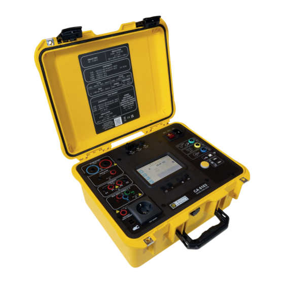
1. COMMISSIONING 1.1. CA 6161 DELIVERY CONDITION Ž Œ “ ‘ ’ ” Figure 1 ① One CA 6161 ② One C19 - Schuko power cord, length 2.5 m. ③ One USB A/B cord. ④ Two high voltage pistols (red and blue) with a 3 m cable. -
Page 6: Ca 6163 Delivery Condition
1.2. CA 6163 DELIVERY CONDITION Ž Œ ‘ ” • “ ’ Figure 2 ① One CA 6163 ② One C19 - Schuko power cord, length 2.5 m. ③ One USB A/B cord ④ Two high voltage pistols (red and blue) with a 3 m cable. ⑤... -
Page 7: Accessories
1.3. ACCESSORIES ■ Pedal for foot control, with 10 m cable. ■ 4-colour signal lamp tower with 5 m cable. ■ Set of two high voltage pistols (red and blue) with a 15 m cable. ■ Kelvin 25 A pistol with a 6 m cable. ■... -
Page 8: Choice Of Language
1.5. CHOICE OF LANGUAGE The language installed by default is that of the country where the instrument is shipped. However, you can change this language. There are more than 15 languages available. Press Figure 3 then Language. Press Select your language and confirm with Figure 4 Press 2 times on to go back to the main menu. -
Page 9: Instrument Presentation
2. INSTRUMENT PRESENTATION 2.1. CA 6161 Cover. On/Off switch. Fuses. HV DIELECTRIC 230 V 50 Hz 16 A 3 kV Socket for Insulation connecting or dielectric 30 A 300 V 16 A 300 V 16 A 300 V the power cord. -
Page 10: Ca 6163
2.3. CA 6163 Cover. On/Off switch. Fuses. HV DIELECTRIC 230 V 50 Hz 16 A 5 kV Socket Dangerous for connecting voltage light 30 A 300 V 16 A 300 V 16 A 300 V the power cord. 600 V 6,3 x 32 6,3 x 32 6,3 x 32... -
Page 11: Instrument Features
■ make insulation measurements up to 100 V, 250 V, 500 V and 1000 V, ■ conduct a dielectric test (up to 3000 V for the CA 6161 and up to 5350 V for the CA 6163) with a fixed voltage or a voltage which gradually increases, ■... -
Page 12: Connectors
2.7. CONNECTORS 30 V Specific green 4-point socket for connecting the dielectric pistol control or the foot control pedal (optional). 30 V Specific yellow 5-point socket to connect the signal lamp tower (optional). 30 V Specific blue 6-point socket for connecting the door closure checker. USB type B socket to connect to a PC in order to be able to transfer recorded data or update firmware. -
Page 13: Configuration
3. CONFIGURATION 3.1. GENERAL When leaving the factory, the instrument is configured in such a way that it can be used without having to modify the parameters. For most measurements, you just need to select the measurement function and press the Start / Stop button. However, you have the option to configure the instrument and the measurements. -
Page 14: Screen Calibration
3.3. SCREEN CALIBRATION At first start up, the instrument will ask you to calibrate the touch screen. Figure 12 Press the target when the instrument asks you to. The instrument then restarts to take the calibration into account. When you want to recalibrate the screen, press and hold the help key 3.4. - Page 15 The instrument allows several user profiles to be managed. Press to enter the user menu. Figure 14 To delete a user. Only the administrator can do this and this action is protected by a non-modifiable password: admin@1234. To create a new user. To modify a user.
-
Page 16: Configuring The Instrument
3.5. CONFIGURING THE INSTRUMENT Press to enter setup. Figure 16 To enter the instrument’s general configuration. The general configuration makes it possible to: ■ select the language, ■ set the date and time as well as their formats, ■ enable or disable the touch screen sound, ■... - Page 17 About To display information about the instrument, including: ■ model, ■ firmware versions, ■ wired card versions, ■ Warranty number, ■ wifi IP address, ■ wifi mac address. Peripherals test To check for accessories plugged into the connectors: ■ foot control pedal, ■...
-
Page 18: Use
4. USE 4.1. KEYS Also at any time, you can press the key to return to home or the key to move up a level. During a measurement, you can press the help key to help you with the connection. 4.2. -
Page 19: Sound Signal
For each heading and sub-level, visual inspection consists of indicating whether the test is passed , or not , or not applicable. Press the blue square until you get the desired value. Figure 20 The overall status of the visual inspection is a logical function of whether or not the headings and sub-levels are validated. Typical inspection libraries (according to EN 60204-1 or EN 61439-1) are present in the instrument. -
Page 20: Start / Stop Button
4.6. START / STOP BUTTON You can only press the Start / Stop button when it is green. If the button Start / Stop is blinking red, conditions do not allow the measurement to be made. Press the Start / Stop button and an error message will let you to correct your connection. -
Page 21: Continuity Measurement
4.8. CONTINUITY MEASUREMENT The continuity measurement is made with the power off. It can be done with 2 or 4 wires. It is used to check the connection between the metal frame of the machine or all the accessible metal parts and the protective conductor (PE). To comply with standard IEC 61557, measurements must be made at a minimum of 200 mA. - Page 22 This measurement ensures better accuracy since the resistance of the leads is not included in the measurement. ■ Select the External Terminals connection. For the CA 6161: ■ Connect a double continuity cord to terminals C1 and P1 of the instrument and connect it to the protective conductor of the machine using 2 crocodile clips.
- Page 23 4.8.3. MEASUREMENT CONFIGURATION The following screen is displayed: Voltage present on the terminals. Stopwatch. Measurement stop criterion. Cord compensation. Measurement in 2 or 4 wires. Figure 24 The parameters are in the blue rectangle. Press to modify them. Shaded information is part of detailed mode. To remove them from the display, press and the display will switch to simple mode In the case of continuity on the test socket, the following screen is displayed:...
- Page 24 ■ Rhigh = maximum value of the continuity resistance. You can also choose MIN for the minimum value, MAX for the maximum value or OFF to give no upper limit. If the measurement is higher than Rhigh, it will be declared invalid. Figure 26 ■...
- Page 25 4.8.4. CORD COMPENSATION When measuring 2-wire continuity on the external terminals or when measuring on the test socket, to obtain a more precise measurement, you can subtract the resistance of the leads from the measurement. ■ Short circuit the test leads according to one of the two diagrams below (depending on the connection). Figure 27 ■...
- Page 26 4.8.6. READING THE RESULT 4.8.6.1. Example for a measurement with a current of 200 mA in 2 wires and in advanced mode Measurement result. Invalid measurement because > Rhigh. Voltage. Measurement current. Maximum value of R during measurement. Figure 28 The measurement is not confirmed because it is higher than Rhigh.
- Page 27 4.8.6.3. Example for a measurement on the test socket with a current of 100 mA without limit When no limit has been set (Rhigh and Rlow are OFF), the measurement is neither valid nor invalid but just done. The box around the measurement is there- fore neither green nor red, but orange.
-
Page 28: Insulation Measurement Resistance
4.9. INSULATION MEASUREMENT RESISTANCE Insulation measurement is done with power off. It is used to check the insulation resistance between conductors and accessible metal parts (earthed or insulated). This test reveals defects due to the ageing of materials. This measurement, generally performed between short-circuited active conductors and earth, consists of applying a DC voltage, measuring the resulting current, and thus determining the value of the insulation resistance. - Page 29 4.9.2.2. Measurement via the test socket ■ Select the Test socket connection ■ Connect the mains plug of the machine to the TEST SOCKET of the instrument. The measurement will be made between L and N connected together and PE. Figure 33 4.9.3.
- Page 30 ■ Stop Criterion: The measurement stops either manually or at the end of the defined duration. You can also make this choice by pressing the symbol. ■ the measurement will last the time required for its completion. ■ the measurement will last for the time you have programmed. the measurement duration is manual.
- Page 31 4.9.5. READING THE RESULT 4.9.5.1. Example of a measurement with a test voltage of 500 V and in advanced mode Measurement result. Measurement valid because it is between Rlow and Rhigh. Measurement duration. Test voltage. Measurement current. Figure 36 4.9.5.2. Example of a measurement with a test voltage of 1000 V and in normal mode Measurement result.
-
Page 32: Dielectric Test
4.10. DIELECTRIC TEST A dielectric test between two conductive parts makes it possible to check the dielectric strength. It ensures that in the event of a fault on the electrical network, for example a surge voltage due to lightning, the two conductive parts will remain insulated and will not cause a short circuit. - Page 33 In the case of a transformer, place each high voltage pistol on one winding of the transformer. Figure 39 During the measurement, you will have to press the triggers of the 2 pistols to release their tips. So you no longer have a hand available to press the Start / Stop button on the instrument.
- Page 34 OFF to give no lower limit. If the measurement is less than Ilow, it will be declared invalid. ■ Unom = test voltage value: between 40 and 3,000 V for the CA 6161 and 5,350 V for the CA 6163.
- Page 35 Figure 44 ■ Unom = test voltage value: between 40 and 3,750 V for the CA 6161 and 5,350 V for the CA 6163. ■ Tramp up = duration of the voltage rise between Ustart and Unom. It can range from 1 to 60 seconds.
- Page 36 4.10.3. DOOR CLOSED CHECKER, By default the door closed checker is disabled. To activate it, follow the following procedure: ■ Go to the home screen then in user profiles Figure 45 ■ Select the Admin profile. The instrument asks you to enter the password: admin@1234. The password is case sensitive! , then in the general settings ■...
- Page 37 When you enter dielectric tests, the door checker is active. Figure 47 ■ Plug the door checker into the blue connector. If the door is not closed when you start the test, the instrument notifies you and the test is impossible: Figure 48...
- Page 38 4.10.4. PERFORMING A DIELECTRIC TEST Before starting a measurement, make sure that the Uini voltage is zero. If a voltage of more than 90 V is present on the terminals, the instrument signals this and blocks the measurement. During the dielectric test, both hands must be on the high voltage pistols. You can only start the measurement, by pressing the trigger of the red pistol, when the Start / Stop button is green.
- Page 39 4.10.5. READING THE RESULT 4.10.5.1. Example for a fixed voltage dielectric test with a voltage of 1000 V Measurement result. Valid measurement because between Ilow and Ihigh. Voltage. Maximum value of I during measurement. Figure 50 4.10.5.2. Example of a fixed voltage dielectric test with a voltage of 400 V stopped before the end of the programmed duration Measurement result.
- Page 40 4.10.5.3. Example for a dielectric ramp test with a voltage of 1000 V Measurement result. Valid measurement because between Ilow and Ihigh. Voltage. Maximum value of I during measurement. Figure 52 You can save the measurement result by pressing If you have connected a printer to the instrument you can also print a label by pressing the key.
-
Page 41: Differential Test (Rcd)
4.11. DIFFERENTIAL TEST (RCD) The instrument can perform three types of test on RCDs: ■ a non-tripping test. ■ a tripping test in pulse mode, ■ a tripping test in ramp mode. The non-tripping test checks that the differential does not trip at a current of 0.5 I . - Page 42 4.11.2.1. With the tripod cord - Schuko plug ■ Connect the tripod plug to terminals L, N, PE of the instrument. ■ Connect the Schuko plug to a socket protected by the circuit breaker to be tested. Figure 53 4.11.2.2. With the tripod cord - 3 safety cords ■...
- Page 43 4.11.2.3. Upstream downstream assembly This connection is used to test a differential located downstream of another whose nominal current is smaller. ■ Connect the tripod plug to terminals L, N, PE of the instrument. ■ Connect the red lead to one of the installation phases before the differential to be tested. ■...
- Page 44 4.11.3. MEASUREMENT CONFIGURATION 4.11.3.1. RCD without tripping Voltage present on the terminals. Frequency of this voltage. Signal waveform. Figure 57 The parameters are in the blue rectangle. Press to modify them. ■ Ul = fault voltage: 25, 50 or 65 V. This is the maximum voltage that the differential test can generate. The voltage of 50 V is the standard voltage (default).
- Page 45 Type of RCD Ifactor Iform (mA) Idn-var ∆N 0.5I 10, 30, 100, 300, 500, 1,000 [6; 1,000] ∆N 10, 30, 100, 300, 500, 1,000 [6; 1,000] ∆N 10, 30, 100, 300, 500 [6; 500] ∆N 10, 30, 100, 300 [6; 300] ∆N 0.5 I 10, 30, 100, 300, 500, 1,000...
- Page 46 In addition to the previous settings: Ifactor = multiplicative factor of I : 0.5, 1, 2, 4, 5 or 10. The possible values depend on the waveform of the signal, the value ∆N of I and the type of differential (see table above). ∆N 4.11.3.3.
- Page 47 4.11.5.2. Example of a pulse RCD test, for a 30 mA circuit breaker, type B, signal Measurement result. The measurement is valid because Ttrip < 200 ms. Voltage before the test. Figure 61 4.11.5.3. Example for a ramp RCD test, for a 100 mA circuit breaker, type A, signal Measurement result.
- Page 48 4.11.6. ERROR INDICATION The most common errors in a differential test are: ■ Connection error: the Start / Stop button blinks red. Correct the connection. If necessary, use the tripod lead - 3 safety leads rather than the tripod lead - Schuko plug. ■...
-
Page 49: Loop Impedance Measurement (Zs)
4.12. LOOP IMPEDANCE MEASUREMENT (Zs) In a TN or TT type installation, the loop impedance measurement is used to calculate the short-circuit current and to size the protections of the installation (fuses or differentials), in particular in terms of breaking capacity. In a TT type installation, the loop impedance measurement makes it easy to determine the value of the earth resistance without having to plant a stake or cut off the power supply to the installation. - Page 50 Figure 63 4.12.2.2. With tripod cord - Shuko plug ■ Connect the tripod plug to terminals L, N, PE of the instrument. ■ Connect the Schuko plug to a socket on the circuit to be tested. Figure 64 4.12.3. MEASUREMENT CONFIGURATION The following screen is displayed: Voltage present on the terminals.
- Page 51 The parameters are in the blue rectangle. Press to modify them. ■ Limit = Ik, Zs, Isc or OFF. To choose whether the measurement will be validated by Ik, Zs, Isc or none of the three. ■ Ik-high = maximum value of the short-circuit current. You can also choose MIN for the minimum value, MAX for the maximum value or OFF to give no upper limit.
- Page 52 4.12.5. READING THE RESULT 4.12.5.1. Example of a loop impedance measurement without tripping with a threshold on Zs Measurement result. Measurement valid because Zs < Zs-high. Calculated short-circuit current. Resistive part of Zs. Inductive part of Zs. Figure 66 4.12.5.2. Example of a loop impedance measurement without tripping with a threshold on Ik Invalid measurement because Ik >...
- Page 53 With a higher measurement current, measurement of Zs is more accurate. Be careful not to connect the instrument’s power supply to the circuit to be tested. Otherwise, when tripped it will turn off. 4.12.5.4. Example of a loop impedance measurement without tripping with a threshold on Isc Invalid measurement because Isc >...
-
Page 54: Line Impedance Measurement (Zi)
4.13. LINE IMPEDANCE MEASUREMENT (Z Line impedance measurement Zi (between L-N, or L1-L2, or L2- L3 or L1- L3) is used to calculate the short-circuit current and to size the protections of the installation (fuse or differential), whatever neutral system the installation has. 4.13.1. - Page 55 ■ Connect the red lead to the phase of the installation. ■ Connect the blue lead to the neutral of the installation. ■ Plug the green cord into the installation PE. If L and N are reversed, the instrument reports it but measurement is possible.
- Page 56 ■ Limit = Ik, Zi, Isc or OFF. To choose whether the measurement will be validated by Ik, Zi, Isc or none. ■ Ik-high = maximum value of the short-circuit current. You can also choose MIN for the minimum value, MAX for the maximum value or OFF to give no upper limit.
- Page 57 4.13.5.2. Example for a line impedance measurement with a threshold on Ik Measurement valid because Ik > Ik-high. Voltage during measurement. Figure 75 4.13.5.3. Example of a line impedance measurement with a threshold on Isc Invalid measurement because Isc < Isc-high. Figure 76 You can save the measurement result by pressing If you have connected a printer to the instrument you can also print a label by pressing the...
-
Page 58: Power Measurement
4.14. POWER MEASUREMENT This function is used to measure: ■ apparent power S, ■ active power P, ■ current I consumed by the machine, ■ voltage Ul-n, ■ frequency f, ■ power factors PF and cos φ, ■ total harmonic distortion in THDi current, ■... - Page 59 4.14.2.2. With the tripod cord - 3 safety cords and the (optional) G72 clamp on a single-phase network This connection is used for a machine operating on single-phase and whose current consumption is higher than 16 A. ■ Choose the Clamp connection.
- Page 60 4.14.3. MEASUREMENT CONFIGURATION For a measurement on the test socket, the following screen is displayed: Stop criterion. Figure 80 The parameters are in the blue rectangle. Press to modify them. ■ Phigh = maximum value of active power. You can also choose MIN for the minimum value, MAX for the maximum value or OFF to give no upper limit.
- Page 61 In the case of a measurement with clamp, the following screen is displayed: Stop criterion. Single-phase or three-phase network. The voltage is zero because it will only be measured during the measurement. Figure 81 It is the same screen as for the measurement on the test socket but with the choice of the network in addition. Shaded information is part of detailed mode.
- Page 62 4.14.5. READING THE RESULT 4.14.5.1. Example of a power measurement on the test socket Measurement result, apparent power. Valid measurement because: Plow < P < Phigh and Slow < S < Shigh and Ilow < I < Ihigh Power factor PF. cos φ.
-
Page 63: Power And Leakage Current Measurement (Ca 6163)
4.15. POWER AND LEAKAGE CURRENT MEASUREMENT (CA 6163) This measurement makes it possible to measure the power consumed by the machine, the leakage current in the PE and the contact current. A leakage current is a sign of defective insulation. It may be due to ageing materials or a shock. As soon as its value reaches a few mA, it becomes dangerous for the user who risks electric shock in the event of a fault on the PE. - Page 64 4.15.2. MEASUREMENT CONFIGURATION The following screen is displayed: Stop criterion. Figure 85 The parameters are in the blue rectangle. Press to modify them. ■ Idiff-high = maximum value of the leakage current. You can also choose MIN for the minimum value, MAX for the maximum value or OFF to give no upper limit.
- Page 65 ■ Delay = time that elapses between the first measurement and the measurement with L and N reversed. Shaded information is part of detailed mode. To remove them from the display, press and the display will switch to simple mode 4.15.3.
- Page 66 4.15.4.2. Example of a power and leakage current measurement and a threshold of perception Invalid measurement because P > Phigh and S > Shigh Stopwatch. Apparent power. Active power. Total harmonic distortion in current and voltage. Figure 87 4.15.5. ERROR INDICATION The most common error in power and leakage current measurement is: ■...
-
Page 67: Leakage Current Measurement
4.16. LEAKAGE CURRENT MEASUREMENT There are 3 leakage current measurements: ■ direct leakage current, ■ differential leakage current, ■ leakage current by substitution (CA 6163). 4.16.1. DESCRIPTION OF THE MEASURING PRINCIPLE ■ For direct leakage current measurement, the instrument measures the leakage current flowing in the PE. Press the Unit tests icon then Direct leakage current ■... - Page 68 4.16.2.2. With the G72 clamp (optional) for direct leakage current measurement This connection is used for a machine operating on single-phase whose current consumption is higher than 16 A or for a machine operating on three-phase. ■ Choose the Clamp connection.
- Page 69 4.16.2.4. Measurement via the test socket for a substitution current measurement (CA 6163) This connection is used for a machine operating on single-phase and whose current consumption is less than 16 A. ■ Connect the mains plug of the machine to the TEST SOCKET of the instrument. Figure 91 4.16.3.
- Page 70 ■ Isubs-low = minimum value of substitution leakage current. You can also choose MIN for the minimum value, MAX for the maximum value or OFF to give no lower limit. If the measure of Isubs is less than Isubs-low, it will be declared invalid. ■...
- Page 71 4.16.4. TAKING A LEAKAGE CURRENT MEASUREMENT Press the Start / Stop button to start the measurement. You can only press the Start / Stop button when it is green. It turns red for the duration of the measurement then turns off. START START START...
- Page 72 4.16.5.3. Example of a leakage current measurement by substitution (CA 6163) Measurement result, leakage current by substitution. Measurement invalid because Isubs > Isubs-high. Figure 96 4.16.6. ERROR INDICATION The most common error in power and leakage current measurement is: ■ A mains voltage non-compliant in frequency, signal waveform, voltage level.
-
Page 73: Contact Current Measurement (Ca 6163)
4.17. CONTACT CURRENT MEASUREMENT (CA 6163) This measurement makes it possible to measure the contact current, i.e. the current that a user would experience when touching an accessible metal part of the machine. A contact current is a sign of defective insulation. It may be due to ageing materials or a shock. - Page 74 4.17.1.2. With the tripod cord - 3 safety cords single-phase This connection is used for a machine operating on single-phase and whose current consumption is higher than 16 A. ■ Choose the tripod connection ■ Connect the tripod plug to terminals L, N, PE of the instrument. ■...
- Page 75 4.17.2. MEASUREMENT CONFIGURATION For a measurement on the test socket, the following screen is displayed: Stop criterion. Figure 100 The parameters are in the blue rectangle. Press to modify them. ■ Imax-high = maximum value of the contact current. You can also choose MIN for the minimum value, MAX for the maximum value.
- Page 76 In the case of a measurement with a tripod cord, the following screen is displayed: Figure 101 There are fewer parameters than in the case of a measurement on the test socket. Shaded information is part of detailed mode. To remove them from the display, press and the display will switch to simple mode 4.17.3.
- Page 77 4.17.4. READING THE RESULT 4.17.4.1. Example of a measurement on the test socket without inversion of L and N Measurement result, maximum contact current. Invalid measurement because Imax > threshold of perception. Alternating part of the contact current. Continuous part of the contact current. Maximum contact current.
-
Page 78: Phase Rotation
4.18. PHASE ROTATION This measurement is done on a three-phase network. It makes it possible to control the order of the phases of this network. 4.18.1. DESCRIPTION OF THE MEASURING PRINCIPLE The instrument checks the unbalance rate of the network, then it compares the phases to detect their order (forward or reverse direction). - Page 79 4.18.4. READING THE RESULT 4.18.4.1. Example of a phase order in the forward direction Measurement result: 1-2-3 indicates a direct rotation, 3-2-1 indicates reverse rotation. Direct rotation. Voltage between the phases. Figure 105 4.18.4.2. Example for a phase order in reverse rotation Reverse rotation.
- Page 80 4.18.4.3. Example of an undetermined phase order Figure 107 4.18.5. ERROR INDICATION The most common errors in the case of a phase rotation direction test are: ■ One of the three voltages is out of the measurement range (connection error). ■...
-
Page 81: Discharge Time
4.19. DISCHARGE TIME This measurement makes it possible to know the discharge time due to the capacitors in the machine, from the operating voltage to a voltage that is not dangerous for the user. Press the Unit tests icon then Discharge time 4.19.1. - Page 82 4.19.1.3. With the tripod cord - 3 three-phase safety leads This connection is used for a machine operating on single-phase whose current consumption is higher than 16 A or for a machine operating on three-phase. ■ Choose the Tripod connection. ■...
- Page 83 ■ Duration: duration of voltage application in seconds before the power supply is cut off. You can also choose MIN for the mini- mum time or MAX for the maximum time. In the case of a measurement with a tripod cord, the following screen is displayed: Figure 112 There is no duration since it is the user who cuts off the power.
- Page 84 4.19.4. READING THE RESULT 4.19.4.1. Example of a measurement on the test socket Measurement result, discharge time. Measurement valid because T < Thigh. Supply voltage. Peak supply voltage. Figure 113 4.19.4.2. Example of a measurement with a tripod lead Invalid measurement because T > Thigh. Supply voltage.
-
Page 85: Auto Script
4.20. AUTO SCRIPT You can perform multiple unit tests in a row in a test sequence. To do this, you must first programme your test sequence in the MTT software (§ 7). In the Instrument menu, select Auto Script. In the Auto Script you can put: ■... - Page 86 Choose the one you want to run. The instrument displays the details of the actions to be performed. Display a text. Display an image. Continuity measurement on the external terminals, timed duration, in 2 wires, under 200 mA. Loop of 30 measurements. Saving.
-
Page 87: Use Of Accessories
5. USE OF ACCESSORIES To facilitate the use of your instrument, you have a large number of accessories at your disposal. 5.1. PRINTER ■ Connect the printer to mains. ■ Connect the printer to one of the two USB ports marked . -
Page 88: Wiring Extension Connectors
The 3 extension connectors provided let you adapt an accessory that you already have (pedal for foot control, signal lamps tower or door closed checker) for use with the CA 6161 or the CA 6163. ■ Unscrew the connector and remove the centre part. -
Page 89: Lamp Tower
5.5. LAMP TOWER To know the status of a measurement without having to look at the instrument’s screen, you can use the lamp tower. Plug it into the yellow connector The blinking red light indicates that the instrument is generating a dangerous voltage (when measuring insulation or in dielectric test). -
Page 90: Memory Function
6. MEMORY FUNCTION 6.1. MEMORY ORGANISATION The memory is organised by sites, objects, Auto Script and measurements. Memory Site 1 Object 1 Auto Scripts 1 Measurement 1 Measurement 2 Measurement 3 Auto Scripts 2 Measurement 1 Measurement 1 Measurement 2 Object 2 Auto Scripts 1 Measurement 1... -
Page 91: Saving A Measurement
6.2. SAVING A MEASUREMENT At the end of each measurement, you can save it by pressing The instrument offers to save the measurement in the last location used. You can confirm or choose a different location. Press to create a site. Figure 122 The instrument displays all existing sites. - Page 92 Press to create the object. Figure 125 The instrument displays all existing objects. For now, there are none. To create a new object, press New Object and confirm. Figure 126 Enter the name of the object and confirm. Here Machine_01. You can add a description and serial number and then confirm.
-
Page 93: Review Of Recordings
6.3. REVIEW OF RECORDINGS To review measurements, start from the home screen and press Choose the site. Figure 128 Choose the object. ■ If the symbol is , then all the measure- ments made on this object are valid. ■ If it is , at least one of the measurements is invalid. -
Page 94: Memory Management
To review a measurement, select it. The measurement is displayed as it was when it was saved. The yellow status bar indicates that this is a memory replay. To delete the measurement. Figure 131 6.4. MEMORY MANAGEMENT To manage memory, start from the Home screen and press You can: ■... -
Page 95: Mtt Application Software
7. MTT APPLICATION SOFTWARE The MTT (Machine Tester Transfer) application software allows you to: ■ configure the instrument and measurements, ■ start the measurements, ■ programme Auto Scripts, ■ transfer the data recorded in the instrument to a PC. MTT also allows exporting the configuration to a file and importing a configuration file. 7.1. -
Page 96: Technical Characteristics
8. TECHNICAL CHARACTERISTICS 8.1. GENERAL TERMS OF REFERENCE Quantity of influence Reference values Temperature 23 ± 2°C Relative humidity 45 to 75% RH Supply voltage 230 V, 50 Hz Electric field ≤ 1 V/m Magnetic field < 40 A/m Intrinsic uncertainty is the error defined in the reference conditions. It is expressed in % of the reading (R) with an offset in number of points: ±... - Page 97 Current measurement Measurement range 0.01 - 0.99 A 0.8 - 40.00 A Resolution 10 mA 100 mA Intrinsic uncertainty ± (3 % R + 3 pt) Continuity measurement under 100 mAac Measurement range 0.05 - 19.99 Ω 18.0 - 120.0 Ω Resolution 10 mΩ...
- Page 98 10 nA 100 nA 1 µA Intrinsic uncertainty ± (10 % R + 3 pt) Insulation measurement CA 6161 Measuring range under 100 V 0.000 - 9.999 MΩ 8.00 - 99.99 MΩ Measuring range under 250 V 0.000 - 9.999 MΩ...
- Page 99 Resolution Intrinsic uncertainty ± (2 % R + 2 pt) For the CA 6161, above 3750 V, the instrument displays > 3750 V. For the CA 6163, above 6250 V, the instrument displays > 6250 V. Current measurement Measurement range 0.5 - 99.9 mA...
- Page 100 Generation of the tripping current in pulse mode Without tripping With tripping 0.5 I 0.5 I 10 I ∆N ∆N ∆N ∆N ∆N ∆N ∆N (mA) ∆N 1000 1200 1500 1000 1400 1000 1000 1000 1400 2 Ivar 2 Ivar 4 Ivar 5 Ivar 7 Ivar...
- Page 101 Loop impedance measurement without tripping Zs and Rs Measurement range 0.20 - 1.99 Ω 2.00 - 39.99 Ω 40.0 - 399.9 Ω 400 - 2,000 Ω Resolution 10 mΩ 10 mΩ 100 mΩ 1 Ω Intrinsic uncertainty ± (15 % R + 3 pt) ±...
- Page 102 Line impedance measurement Zi, Ri Measurement range 0.05 - 0.499 Ω 0.500 - 3.999 Ω 4.00 - 39.99 Ω 40.0 - 400.0 Ω Resolution 1 mΩ 1 mΩ 10 mΩ 100 mΩ Intrinsic uncertainty ± (10 % R + 20 pt) ±...
- Page 103 Apparent power measurement S Measurement range 0.21 - 99.99 VA 80.0 - 999.9 VA 800 - 4240 VA Resolution 10 mVA 100 mVA 1 VA Intrinsic uncertainty ± (2 % R + 2 pt) Above 7000 VA, the instrument displays > 7000 VA. Voltage measurement Ul-n, Ul-pe, Un-pe Measurement range 207.0 - 265.0 V...
- Page 104 8.2.9. POWER ON THE TRIPOD CORD WITH THE G72 CLAMP (OPTIONAL) The voltage is measured on the tripod socket and the current is measured by the current clamp. Particular reference conditions: AC voltage frequency: 45 to 55 Hz Signal waveform: sinusoidal cos φ: 0.5 capacitive to 0.8 inductive DC Component: None Voltage measurement U...
- Page 105 THD measurements Particular reference conditions: AC voltage frequency: 45 to 55 Hz cos φ: 1 DC Component: None Measurement of total harmonic voltage distortion THDu n=25 Measurement range 0.0 - 100.0 % ∑ √ ² Resolution 0.1% THDu = Intrinsic uncertainty ±...
- Page 106 8.2.11. POWER AND LEAKAGE CURRENT MEASUREMENT (CA 6163) For power, see § 8.2.8. For leakage current, see § 8.2.10. For contact current, see § 8.2.12. 8.2.12. CONTACT CURRENT MEASUREMENT Particular reference conditions: Peak factor = 2 DC component: zero Contact current measurement Imax, Iac Measurement range 0.01 - 30.00 mA Resolution...
-
Page 107: Variations In The Field Of Use
Voltage measurement with tripod lead Uini and Ul-n Measurement range 1.0 - 440.0 V Resolution 0.1 V Intrinsic uncertainty ± (3 % R + 3 pt) Impedance of each input 27.8 MΩ Voltages are measured in RMS. Only Ul-n is displayed. Discharge time measurement Measurement range 0.1 - 9.9 s... - Page 108 = influence of frequency. = influence of repeatability. The operating uncertainties below are only given for the measurements covered by standard IEC 61557. 8.3.2. CONTINUITY MEASUREMENT Operating uncertainty in insulation measurement Influence quantities Code Area of influence Influence Position of the instrument Supply voltage Ul-n 207 ...
- Page 109 8.3.5. DIFFERENTIAL TEST The intrinsic uncertainty is determined under the following reference conditions: ■ Vn-pe < 1 V ■ the network voltage does not vary by more than 1 V during the measurement. ■ the leakage current in the network protected by the differential is negligible. ■...
- Page 110 8.3.6. LOOP AND LINE IMPEDANCE MEASUREMENT The intrinsic uncertainty is determined under the following reference conditions: ■ the network on which the loop impedance measurement is carried out is under constant load conditions, with the exception of load changes caused by the measuring instrument. ■...
-
Page 111: Power Supply
8.3.8. LEAKAGE CURRENT MEASUREMENT WITH THE CURRENT CLAMP The G72 clamp is class 3 according to IEC 61557-13 from 5 mA. Operating uncertainty in leakage current measurement Influence quantities Code Area of influence Influence Position of the instrument Supply voltage Ul-n 207 ... -
Page 112: Communication
Dimensions (W x D x H) 407 x 341 x 205 mm Weight about 16 kg for the instrument 4.8 kg approximately for the accessories delivered with the CA 6161 5.5 kg approximately for the accessories delivered with the CA 6163 Protection index IP 64 according to IEC 60 529 cover closed. -
Page 113: Maintenance
9. MAINTENANCE Except for the fuses and the TEST SOCKET, the instrument does not contain any parts that can be replaced by untrained and unauthorised personnel. Any unapproved work or replacement of any part by equivalents may gravely compromise safety. 9.1. -
Page 114: Replacement Of The Test Socket
■ Remove the defective fuse and replace it with a new fuse. To ensure continuity of safety, replace a defective fuse only with a fuse with strictly identical characteristics. F1: FF 30 A 300V 6.3 x 32mm F2 and F3: FF 16 A 300V 6.3 x 32mm ■... -
Page 115: Storing The Instrument
9.6. UPDATING THE EMBEDDED SOFTWARE In a constant concern to provide the best possible service in terms of performance and technical developments, Chauvin Arnoux offers you the possibility of updating the software integrated into this instrument by downloading the new version free of charge from our website. - Page 116 Then it starts the update. It tells you that it is in progress and that you should not turn off the instrument. Figure 139 The update takes several minutes and then the instrument signals that it is complete. Restart it. Figure 140 In the event of an error, the instrument reports it.
-
Page 117: Calibrating The Instrument
9.7. CALIBRATING THE INSTRUMENT Calibration must be carried out by qualified personnel. It is recommended to do this once a year. This operation is not covered by the warranty. 9.7.1. EQUIPMENT REQUIRED ■ An AC voltage generator capable of generating 10 and 50 V at 50 Hz, accuracy 0.1% ■... - Page 118 You can choose to: ■ Consult the date of the last calibration. ■ Restore the original calibration ■ Calibrate the instrument, step by step. Figure 144 Press Calibration steps. Figure 145 Press the first step. Figure 146...
-
Page 119: Memory Check
■ Make the requested connection. ■ Press the Start / Stop button. The instrument makes the first calibration and returns to the previous screen indicating whether the step has been confirmed or not ■ Disconnect the instrument before proceeding to the next step. Figure 147 Do this for the 35 steps of the calibration. -
Page 120: Warranty
10. WARRANTY Except as otherwise stated, our warranty is valid for 24 months starting from the date on which the equipment was sold. The extract from our General Terms of Sale is available on our website. www.chauvin-arnoux.com/en/general-terms-of-sale The warranty does not apply in the following cases: ■... -
Page 121: Appendix
11. APPENDIX 11.1. DEFINITION OF SYMBOLS Here is the list of symbols used in this document and on the instrument display. test valid. test invalid. test incomplete. ΔU-TEST maximum value of the voltage according to the cross-sectional area of the cable for continuity measurements under 10 A. - Page 122 inductive part of line impedance ZI. inductive part of loop impedance Zs. N terminal (neutral). φ phase shift of current with respect to voltage. active power P = U . I. PF. P1, P2 continuity voltage measurement terminals. protective conductor. power factor (cos φ...
- Page 123 line impedance. It is the impedance in the loop between phase and neutral or between two phases (line loop impedance). Zi-high high threshold of line impedance. Zl-n impedance in the L-N loop. Zl-pe impedance in the L-PE loop. impedance in the loop between the phase and the protective conductor. Zs-high high impedance threshold in the loop.
-
Page 124: Earth Connection Diagrams
11.2. EARTH CONNECTION DIAGRAMS 11.2.1. TT NETWORK The neutral is connected to earth and the masses of the installation are connected to earth. Distribution transformer User 11.2.2. TN NETWORK The neutral is connected to earth and the masses of the installation are connected to neutral. There are 2 TN schemes: ■... -
Page 125: Fuse Table
11.3. FUSE TABLE According to standard EN60227-1 § 5.6.3 DIN gG according to standards IEC60269-1, IEC60269-2 and DIN VDE 0636-1/2 Iks: breaking current for a given time (breaking time indicated for each table) 11.3.1. BREAK TIME = 5 s Nominal current Delayed fuse DIN gG/gL fuse RCD LS-B... - Page 126 11.3.2. BREAKING TIME = 400 ms Nominal current Delayed fuse DIN gG/gL fuse RCD LS-B RCD LS-C RCD LS-D Iks max (A) Iks max (A) Iks max (A) Iks max (A) Iks max (A) 1000 1260 1018 1455 1678 2530 2918 4096 5451...
- Page 127 11.3.3. BREAKING TIME = 200 ms Nominal current Delayed fuse DIN gG/gL fuse RCD LS-B RCD LS-C RCD LS-D Iks max (A) Iks max (A) Iks max (A) Iks max (A) Iks max (A) 1000 1260 1600 1195 1000 2000 1708 1250 2500...
- Page 128 11.3.4. BREAKING TIME = 100 ms Nominal current Delayed fuse DIN gG/gL fuse RCD LS-B RCD LS-C RCD LS-D Iks max (A) Iks max (A) Iks max (A) Iks max (A) Iks max (A) 140.4 453.2 1000 1260 1100 1600 1450 1000 2000...
- Page 129 11.3.5. BREAKING TIME = 35 ms Nominal current Delayed fuse DIN gG/gL fuse RCD LS-B RCD LS-C RCD LS-D Iks max (A) Iks max (A) Iks max (A) Iks max (A) Iks max (A) 1000 1,217 1260 1,567 1600 2,075 1000 2000 2,826...
- Page 130 FRANCE INTERNATIONAL Chauvin Arnoux Chauvin Arnoux 12-16 rue Sarah Bernhardt Tél : +33 1 44 85 44 38 92600 Asnières-sur-Seine Fax : +33 1 46 27 95 69 Tél : +33 1 44 85 44 85 Our international contacts Fax : +33 1 46 27 73 89 info@chauvin-arnoux.com...
Need help?
Do you have a question about the CA 6161 and is the answer not in the manual?
Questions and answers