Extron electronics RGB-DVI 300 User Manual
High performance video scalers.
dvi & hdmi
Hide thumbs
Also See for RGB-DVI 300:
- User manual (68 pages) ,
- Specifications (2 pages) ,
- Setup manual (2 pages)

Related Manuals for Extron electronics RGB-DVI 300


Summary of Contents for Extron electronics RGB-DVI 300
- Page 1 User Guide DVI & HDMI ® RGB-DVI 300 and RGB-HDMI 300 (A) High Performance Video Scalers 68-1407-01 Rev. E 11 18...
- Page 2 Safety Instructions Safety Instructions • English Istruzioni di sicurezza • Italiano AVVERTENZA: Il simbolo, , se usato sul prodotto, serve ad WARNING: This symbol, ,when used on the product, is avvertire l’utente della presenza di tensione non isolata pericolosa intended to alert the user of the presence of uninsulated dangerous all’interno del contenitore del prodotto che può...
- Page 3 より 『Extron Safety www.extron.com and Regulatory Compliance Guide』 (P/N 68-290-01) をご覧ください。 Copyright © 2009-2018 Extron Electronics. All rights reserved. www.extron.com All trademarks mentioned are the property of their respective owners.. Trademarks All trademarks mentioned in this guide are the properties of their respective owners.
- Page 4 FCC Class A Notice This equipment has been tested and found to comply with the limits for a Class A digital device, pursuant to part 15 of the FCC rules. The Class A limits provide reasonable protection against harmful interference when the equipment is operated in a commercial environment. This equipment generates, uses, and can radiate radio frequency energy and, if not installed and used in accordance with the instruction manual, may cause harmful interference to radio communications.
- Page 5 Conventions Used in this Guide Notifications In this user guide, the following are used: WARNING: Potential risk of severe injury or death. AVERTISSEMENT : Risque potentiel de blessure grave ou de mort. CAUTION: Risk of minor personal injury. ATTENTION : Risque de blessure mineure. ATTENTION: •...
-
Page 7: Table Of Contents
Introduction Software and Firmware ............1 ........24 About the RGB-DVI 300 and RGB-HDMI 300 (A) ..1 Downloading Software or Firmware .......24 RGB-DVI 300 and RGB-HDMI 300 (A) Features ..1 Signal Processing Products Control Program ..25 RGB-DVI 300 and RGB-HDMI 300 (A) Installing the SPPCP .........25... - Page 8 RGB DVI 300 and RGB HDMI 300 (A) • Contents viii...
-
Page 9: Introduction
A single video output at any of a large range of scaled resolutions and refresh rates is provided through a DVI-I (RGB-DVI 300) or HDMI (RGB-HDMI 300 and RGB-HDMI 300 A) connector. Input and output settings, picture controls, and advanced settings can be adjusted through the front panel menu with on-screen display, using the Extron Signal Processing Products Control Program (SPPCP), or by RS-232, using the Extron Simple Instruction Set (SIS) commands. -
Page 10: Rgb-Dvi 300 And Rgb-Hdmi 300 (A) Application Diagram
Behind flat panel mounting — The compact size allows the unit to be concealed by mounting it to the wall behind a flat panel display. There are a wide range of mounting options (see Wall Mounting on page 40). RGB-DVI 300 and RGB-HDMI 300 (A) Application Diagram Extron Extron... -
Page 11: Cabling
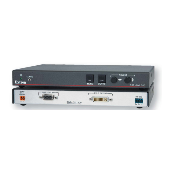
RGB input RS-232 connector Audio Input (RGB HDMI 300 A model only) Figure 2. RGB-HDMI 300 A (Upper Panel) and RGB-DVI 300 (Lower Panel) Power input — Connect the 12 VDC power supply (provided) to the front panel captive screw connectors. POWER Back Panel 1.0A MAX... - Page 12 NOTE: Do not tin the wires. Tinned wire does not hold its shape and can become loose over time. (R-Y) (B-Y) RGB input — The RGB-DVI 300, RGB-HDMI 300, and RGB-HDMI 300 A accept RGB (RGBHV, RGBS, RGsB, and RsGsBs) and HDTV component (YUV) signals. Connect the input signal to the female 15-pin HD connector on the back of the scaler.
- Page 13 HDMI OUTPUT Figure 5. Digital Output Sockets NOTE: Although the RGB-DVI 300 has a rear panel DVI-I connector, the output signal is DVI-D (digital only). For the RGB-HDMI 300, secure the HDMI cable with the LockIt HDMI lacing bracket provided. Connect a HDMI source device to the HDMI input connector on the RGB-HDMI 300.
-
Page 14: Front Panel Cabling
RS-232 (rear panel) — The video scalers accept SIS commands from a host device such as a computer running the Extron DataViewer utility or other control system. Control commands can be sent through this port or the Config port on the front panel (see “Front Panel Cabling”). -
Page 15: Configuration
Configuration This section discusses the configuration of the scalers using front panel controls and the on-screen display. It is divided into five topics: Terminology • Front Panel Indicators and Controls • Configuration Procedure • Front Panel Menu Controls • On-screen Menus •... -
Page 16: Input Signal
Input Signal Video settings Signal type — RGB or HDTV component (Y, R-Y, B-Y) Total pixels — The total number of pixels in a line, including blanking on both sides of the input active area (active, horizontal sync width, back porch, and front porch). The values can be adjusted from the default value ±512. -
Page 17: Output Signal
Audio settings (RGB-HDMI 300 A model only) Gain and attenuation — Gain increases audio levels (0 to +10 dB). Attenuation reduces audio levels (0 to -18 dB). Audio delay — When video signals are processed, they can be delayed relative to the audio signal. -
Page 18: Output Resolutions And Refresh Rates
Output Resolutions and Refresh Rates Resolution Refresh Rate (Hz) 23.98 29.97 59.94 640x480 800x600 852x480 1024x768 1024x852 1024x1024 1280x768 1280x800 1280x1024 1360x765 1360x768 1365x768 1366x768 1365x1024 1440x900 1400x1050 1680x1050 1600x1200 1920x1200 480p 576p 720p 1080i 1080p 2048x1080 1600x900 Auto Output resolution is based on display EDID. Lock Output rate matches input resolution and refresh rate. -
Page 19: Other Settings
This data can include “InfoFrames” indicating the output color space (RGB or YUV) for the RGB-DVI 300 and RGB-HDMI 300 A and embedded audio (RGB-HDMI 300 A only). Some DVI-only displays may show an erratic or improper video output when HDMI Data is enabled. -
Page 20: Front Panel Indicators And Controls
Figure 11. RGB-DVI 300 and RGB-HDMI 300 A The front panels of the RGB-DVI 300, RGB-HDMI 300, and RGB-HDMI 300 A have a bicolor (green and amber) LED indicator, a Config port, Menu and Enter buttons, and two rotary encoders. -
Page 21: Configuration Procedure
Configuration Procedure NOTE: This section describes how to configure the scalers using the front panel controls and on-screen display. Many of these parameters can also be configured with SIS commands (see page 28) or the SPCPP software (see the SPCPP help file). To set up a scaler, follow these steps: Connect all input and output cabling to the scaler and apply AC power (Power Input see page 3). - Page 22 Table 2. PC, Laptop, and TV Input Rates *NOTE: The RGB-DVI 300 and RGB-HDMI 300 (A) video scalers have a maximum input pixel clock of 162 MHz. WUXGA2 and 1080p PC rates exceed this limit and are sampled with reduced total and active pixel values. If EDID emulation is enabled, between the PC source and the scaler, the source should default to WUXGA1 or HDTV-1080p, each of which can be sampled, pixel for pixel.
-
Page 23: Front Panel Menu Controls
ENTER Figure 12. Menu controls NOTE: The menus for the RGB-DVI 300, RGB-HDMI 300, and RGB-HDMI 300 A are On-Screen Display (OSD). To see menu selections, a display device must be attached to the output of the video scaler/converter. On-screen Menus... -
Page 24: Main Menu
Apart from the heading, the RGB-DVI 300 and RGB-HDMI 300 menus are identical in all • respects and, in most cases, the RGB-DVI 300 menus have been used to illustrate the menu options. The RGB-HDMI 300 A Input Configuration and Output Configuration menus contain •... -
Page 25: Auto Image
Auto Image The Auto-Image function automatically sizes and centers the input to fill the screen. To activate Auto-Image press the Enter button after Auto Image has been selected. Figure 16. Auto Image Menu This feature initiates a one-time Auto-Image on the current input. Auto-Image can also be set Advanced Configuration globally, using the menu (see page 22), to size and center each... -
Page 26: Picture Controls
Picture Controls The Picture Controls submenu sets horizontal and vertical centering, sizing, brightness and contrast, and detail (sharpness) and controls the zoom feature. Use the { knob to select from the submenu, and then press the button. Enter Figure 17. Picture Controls Menu Use the [ knob to adjust the values for... -
Page 27: User Presets
User Presets are a user-defined set of picture control settings for up to three commonly used User Presets aspect ratio settings. When Picture Controls (see page 18) and Input Configuration (see page 20) are set, the current values for Contrast Brightness Detail Horizontal... -
Page 28: Input Configuration
Input Configuration submenu is used to adjust Input Configuration Input Type Total Pixels Phase Horizontal Vertical Start (video), and Horizontal Vertical Active areas. In addition, with the RGB-HDMI 300 A model only, this submenu is used to adjust the Audio Gain &... -
Page 29: Output Configuration
The Output Configuration is used to select a scaler output rate from the various available resolution and refresh rates. The RGB-DVI 300, RGB-HDMI 300, and RGB-HDMI 300 A have a large range of combinations of resolution and refresh rate (see table 1 on page 10). -
Page 30: Advanced Configuration
Advanced Configuration menu configures global settings, including Advanced Configuration Test Pattern Blank Freeze , global Auto Image Auto Memory , and Factory Reset Press the button to display the main menu and use either rotary encoder to select Menu Advanced Configuration . - Page 31 Auto-Image and Auto Memory The Auto-Image and Auto Memory functions work interactively. Either function can be on or off, giving four possible combinations. Auto Image on and Auto Memory on — If the Auto-Image function is on, the input signal is sized and centered to fill the screen.
-
Page 32: Software And Firmware
Firmware Upgrades • Downloading Software or Firmware To download software (SPPCP or Firmware Loader) or to upgrade firmware for the RGB-DVI 300, RGB-HDMI 300, and RGB-HDMI 300 A, follow these instructions. Open a web browser and go to www.extron.com. Figure 25. -
Page 33: Signal Processing Products Control Program
RGB-DVI 300, RGB-HDMI 300, or RGB-HDMI 300 A. Signal Processing Products Control Program All the features of the RGB-DVI 300, RGB-HDMI 300, and RGB-HDMI 300 A that can be controlled by SIS commands can also be controlled by a computer that is running the Signal Processing Products Control Program (SPPCP). -
Page 34: Running The Sppcp
To start the program, click the desktop icon (shown at right) or click the Windows button and select > > Start All Programs Extron Electronics Signal > Processing Signal Processing Products Control Program The Select Connection Type dialog box opens: Figure 28. -
Page 35: Firmware Upgrades
Firmware Upgrades Firmware for the RGB-DVI 300, RGB-HDMI 300, or RGB-HDMI 300 A can be upgraded using the Extron Firmware Loader utility by following the steps below: Power on the scaler and a computer with internet access. Connect the computer to the video scaler through either the front panel Config port or the rear panel RS-232 captive screw connectors. - Page 36 Add Device... screen closes. The main Firmware Loader window is now visible. Figure 32. Firmware Loader Main Window Click Begin. The firmware transfer takes approximately 3 minutes. The progress of the transfer is shown by a green bar in the Total Progress panel.
-
Page 37: Sis Commands
• Introduction to SIS Both the RGB-DVI 300 and the RGB-HDMI 300 (A) accept SIS commands from a host device such as a computer running the HyperTerminal utility or other control system. The host device can be connected to the 3-pin captive screw connector on the rear panel or to the Config port on the front panel. -
Page 38: Symbols Used In This Guide
Symbols Used in this Guide During programming in the field, certain characters are most conveniently represented by their hexadecimal rather than their ASCII values. The table below shows the hexadecimal equivalent of each Command ASCII character. The X/ values defined in this section are the variables used in the fields of the and Response Table for SIS Commands (see page 32). -
Page 39: Audio Command Symbols (Rgb-Hdmi 300 A Only)
16= 16 bit (default) 24= 24 bit Error Messages If the RGB-DVI 300, RGB-HDMI 300, or RGB-HDMI 300 A does not support or recognize the entered commands, one of the following responses may be issued. = Invalid command = Not valid for this config. -
Page 40: Command And Response Table For Sis Commands
Command and Response Table for SIS Commands Command ASCII command Response Additional description (host to device) (device to host) Input Video Format Set Format Atyp1* View Detected Format Atyp1* KEYS: = Input Video Format 0 = No signal (for query only) 1 = RGB (default) 2 = YUV 3 = Auto... - Page 41 Command ASCII command Response Additional description (host to device) (device to host) Vertical Start E X$ Set a Vertical Start Value VSRT Vsrt Increment Vertical Start +VSRT Vsrt Value Decrement Vertical Start -VSRT Vsrt Value View Vertical Start Value VSRT Vsrt KEYS: Vertical start value: from 0 to 255 (the midpoint of 128 is the default value in the input lookup tables)
- Page 42 Command ASCII command Response Additional description (host to device) (device to host) Active Lines E X* Specify a Value ALIN Alin Increment Number of +ALIN Alin Active Lines Decrement Number of -ALIN Alin Active Lines View Number of Active ALIN Alin Lines KEYS:...
- Page 43 Command ASCII command Response Additional description (host to device) (device to host) Detail Filter E X1) X1)] Specify Detail Level HDET Hdet X1)] Increment the Detail Level +HDET Hdet X1)] Decrement the Detail Level -HDET Hdet X1)] View the Current Detail HDET Hdet Level...
- Page 44 Command ASCII command Response Additional description (host to device) (device to host) Zoom Mode X1@] Zoom In +ZOOM Zoom X1@] Zoom Out -ZOOM Zoom X1@] View Current Zoom Value ZOOM Zoom KEYS: = Horizontal and vertical size (range depends on output resolution). Response shows horizontal value first, vertical second. Aspect Ratio Control Fill Output Raster 1ASPR...
- Page 45 Command ASCII command Response Additional description (host to device) (device to host) User Presets X1*] Save User Preset 1Spr X1*] Recall User Preset 1Rpr KEYS: = User Preset (1 to 3) Save command saves the current settings to one of three user presets. The final character of the command is a comma (,). Recall command recalls the user preset values for the current input.
- Page 46 Command ASCII command Response Additional description (host to device) (device to host) Freeze Enable Freeze Frz1 Disable Freeze Frz0 View Freeze Status KEYS: Freeze Status (0= disabled; 1= enabled). RGB Delay Time E X2! X2!] Set Delay Time VDLY Vdly X2!] View Delay Time VDLY...
- Page 47 X2#] General Information • Vid1 Query Model Name RGB-DVI 300 RGB-HDMI 300 RGB-HDMI 300 A Query Model Description Extron Electronics Digital Video Scaler Query Firmware Version x.xx Query Firmware Version x.xx.xxxx (complete) Query Part Number RGB-DVI 300 = 60-906-01 60-xxxx-01...
- Page 48 Command ASCII command Response Additional description (host to device) (device to host) Power Save Mode Enable 1PSAV Psav1 Disable 0PSAV Psav0 View Status PSAV Psav KEYS: = Power Save Mode 0= disabled (the scaler always outputs video) 1= enabled (sync output is disabled when no input is applied) (see Power save mode on page 11 for more information about this command).
-
Page 49: Mounting
• Through-desk Mounting • Wall Mounting The RGB-DVI 300, RGB-HDMI 300, and RGB-HDMI 300 A can be mounted on the wall, using an optional mounting kit. This enables the unit to be concealed behind wall-mounted flat screen monitors (see www.extron.com for suitable options). -
Page 50: Under-Desk Mounting
Under-desk Mounting Mount the unit under a desk or podium, using an optional under-desk mounting kit (see www.extron.com for suitable options). Follow the instructions provided with the kit. Through-desk Mounting Mount the unit through a desk or podium using an optional through-desk mounting kit (see www.extron.com for suitable options). - Page 51 Extron Electronics makes no further warranties either expressed or implied with respect to the product and its quality, performance, merchantability, or fitness for any particular use. In no event will Extron Electronics be liable for direct, indirect, or consequential damages resulting from any defect in this product even if Extron Electronics has been advised of such damage.
Need help?
Do you have a question about the RGB-DVI 300 and is the answer not in the manual?
Questions and answers