Advertisement
MGP 641 • Setup Guide
The MGP 641 is a multi-window video signal processor that displays multiple video sources on a single screen in
picture-in-picture or picture-by-picture format. It features dedicated connectivity for each of the four windows, fully customizable
window layouts, HDCP 2.3 support, logo and background image support, logo keying, and ultra-high resolution support up to
2560x1600 and 4K at 60 Hz on both inputs and outputs. The MGP 641 can be controlled and configured using the front panel
controls, Simple Instruction Set™ (SIS™) commands, the internal web page, and the Videowall Configuration Software (VCS).
This guide provides instructions for an experienced installer to install and configure the MGP 641.
NOTES:
•
For full installation, configuration, and operation details, see the MGP 641 Series User Guide, available at
www.extron.com.
•
The VCS program is available at www.extron.com. For information on using VCS, see the VCS Help File, also available
on the Extron website.
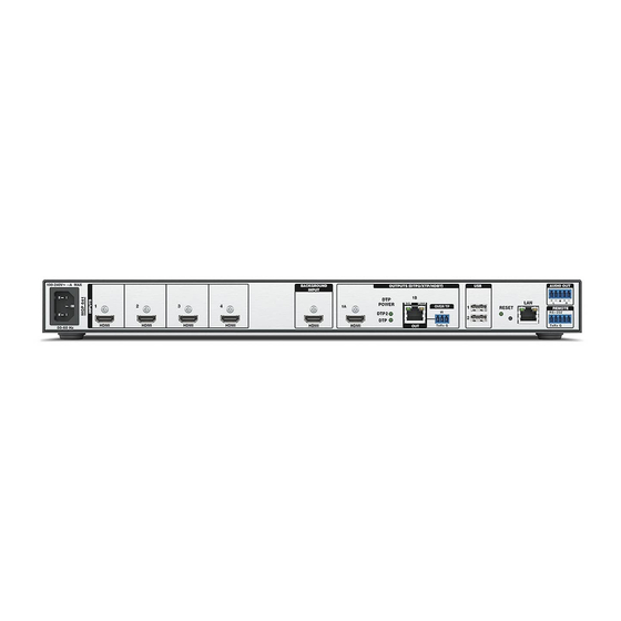
Rear Panel Features and Connections
A A A
100-240V~ 1.5A MAX
1
2
HDMI
HDMI
50 – 60 Hz
A
AC power connector
B
HDMI inputs
C
HDMI live Background Input
D
HDMI output (output 1A)
Rear Panel
Figure 1.
Installation Steps
Mount the MGP to a rack using the pre-installed side mounting brackets. The MGP 641 has a 1U high, full rack wide
1.
enclosure.
Alternatively, attach the four provided rubber feet to the bottom of the MGP and place the unit in the desired location.
Connect HDMI (or DVI with an appropriate adapter) sources to the HDMI input connectors (inputs 1 through 4) (see figure 1,
2.
B
).
If desired, connect a source to the HDMI live Background Input connector (
3.
of this unscaled background video source.
NOTE:
You must set the output resolution to match that of the background source, or the background video is not
displayed. The refresh rates do not need to match.
4.
Make the following output connections as needed:
Connect an HDMI (or DVI with an appropriate adapter) display to the HDMI output 1A connector (
z
Connect a DTP endpoint, XTP matrix switcher, or HDBaseT compatible receiver to the buffered DTP/XTP/HDBT output
z
connector 1B (
F
NOTE:
RS-232 data can be inserted via Ethernet (see the MGP 641 User Guide or the VCS Help File).
To pass infrared data, connect a control device to the 3-pole Over TP IR captive screw connector (see the MGP 641 User
z
Guide for information).
B B B
3
4
HDMI
HDMI
E
DTP remote power LEDs
F
DTP/XTP/HDBT output (output 1B)
G
Over TP IR pass through connector
H
USB Devices connectors
). For cable wiring and recommendations, see the MGP 641 User Guide.
C C C
D D D
E E E F F F G G G
BACKGROUND
OUTPUTS (DTP2/XTP/HDBT)
INPUT
1B
DTP
SIG
LINK
POWER
1A
DTP2
DTP
HDMI
HDMI
OUT
C
). The MGP 641 windows are displayed in front
H H H
I I I
J J J
K K K
DEVICES
AUDIO OUT
USB 3.0
L
LAN
OVER TP
1
RESET
REMOTE
IR
RS-232
2
900mA
Tx
Rx G
Tx Rx G
I
Reset button and LED
J
Ethernet LAN connector
K
Analog Audio Out connector
L
Remote RS-232 connector
D
).
R
L L L
1
Advertisement
Table of Contents

Related Manuals for Extron electronics MGP 641


Summary of Contents for Extron electronics MGP 641
- Page 1 HDCP 2.3 support, logo and background image support, logo keying, and ultra-high resolution support up to 2560x1600 and 4K at 60 Hz on both inputs and outputs. The MGP 641 can be controlled and configured using the front panel controls, Simple Instruction Set™...
- Page 2 VCS or SIS as two discrete mono outputs or as one stereo output (see “Audio Wiring” for details). If the MGP 641 will be connected to a computer or to a host controller for remote control, connect an RS-232 cable from the host to the Tx, Rx, and G pins (the remaining two pins are not used) of the 5-pole Remote RS-232 rear panel connector (see figure 1,...
- Page 3 Setting Up the MGP 641 Using the Front Panel Extron MGP 641 Default Power After installing and connecting the MGP 641, use the front panel controls to configure Vn.nn Cycle 2 sec. and adjust the unit for use. Press the Menu button to access the Main Menu (shown at right).
- Page 4 SIS Commands As an alternative to the front panel controls, you can issue SIS commands via RS-232, USB, or Ethernet from the computer to set up the MGP 641 (see the MGP 641 User Guide at www.extron.com for a complete list of SIS commands).
Need help?
Do you have a question about the MGP 641 and is the answer not in the manual?
Questions and answers