Table of Contents
Advertisement
Quick Links
Extron Electronics, USA
Extron Electronics, Europe
1230 South Lewis Street, Anaheim, CA 92805
Beeldschermweg 6C, 3821 AH Amersfoort
800.633.9876 714.491.1500 FAX 714.491.1517
+31.33.453.4040 FAX +31.33.453.4050
USA
The Netherlands
© 2001 Extron Electronics. All rights reserved.
Extron Electronics, Asia
Extron Electronics Information
135 Joo Seng Rd. #04-01, PM Industrial Bldg.
ExtronWEB
™
: www.extron.com
+65.383.4400 FAX +65.383.4664
ExtronFAX
™
: 714.491.0192
Singapore 368363
24-hour access—worldwide!
User's Manual
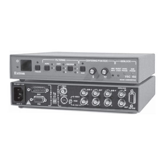
VSC 150
Scan Converter
68-469-01
Printed in the USA
Advertisement
Table of Contents

Related Manuals for Extron electronics VSC 150


Summary of Contents for Extron electronics VSC 150
- Page 1 User’s Manual VSC 150 Scan Converter 68-469-01 Extron Electronics, USA Extron Electronics, Europe Extron Electronics, Asia Extron Electronics Information 1230 South Lewis Street, Anaheim, CA 92805 Beeldschermweg 6C, 3821 AH Amersfoort 135 Joo Seng Rd. #04-01, PM Industrial Bldg. ExtronWEB ™...
- Page 2 Precautions Safety Instructions • English FCC Class A Notice Warning This symbol is intended to alert the user of important Power sources • This equipment should be operated only from the power source indicated on the product. This equipment is intended to be used with a main operating and maintenance (servicing) instructions Note: This equipment has been tested and found to comply with the limits for a power system with a grounded (neutral) conductor.
-
Page 3: Table Of Contents
Using the command/response table ........Command/response table ............. 3-4 Control software for Windows ..........3-6 Installing the software ............3-6 ............3-6 Using the software IR Remote Control ..............3-7 Using the memory feature ............ 3-8 (Continued) VSC 150 • Table of Contents... -
Page 4: Chapter 1 • Introduction
VSC 150 Part Numbers ................... A-1 Specifications ................. A-2 Included Parts ................. A-4 Accessories ................A-4 Chapter One Introduction About this Manual About the VSC 150 Features 68-469-01 D Printed in the USA 01 01 VSC 150 • Table of Contents... -
Page 5: About This Manual
The VSC 150 is 1U high and one half rack wide. It is rack Infrared (IR) remote control — All the functions that can mountable, and has an internal, autoswitching power be controlled via front panel controls can be also be supply. -
Page 6: Chapter 2 • Installation And Operation
Mac-VGA cable connects the VSC 150 to the computer without need for additional adapters. Rack mountability — The VSC 150 can be rack mounted on one side of an optional 1U rack shelf (Extron part #60-190-01). Chapter Two... -
Page 7: Installation Overview
Turn all of the equipment off. Make sure that the Place the VSC 150 on one half of the 1U (one unit high, source computer, the VSC 150, the output devices one unit wide) rack shelf (part #60-190-01). Align the... -
Page 8: Front Panel Features
Installation and Operation, cont’d Front Panel Features 2 seconds to activate Executive mode. Executive mode prevents unauthorized or accidental adjustments to the VSC 150’s settings via front panel controls by locking all FILTERING CENTERING/PAN SIZE GENLOCK the front panel features except centering controls. -
Page 9: Rear Panel Features
Burst Lock (genlock) LED — This lights green to indicate Mac-VGA cable) to use a VGA-type computer as the video that the VSC 150 is receiving a genlock (black burst) sync signal source. signal via the rear panel genlock input connector. Genlock... -
Page 10: Cabling
“Setting Up Genlock and Vertical Interval Switching” monitor or termination adapter is connected. in this chapter. ON — The VSC 150 provides 75 ohm video input RS-232 connector — Connect a computer or RS-232 termination. Select this setting when a control module to this 9-pin D connector to allow local monitor is not used. - Page 11 VGA Input local monotor. Mac Input of the VSC 150 as shown in the illustration on the next A typical VSC 150 system application page. Otherwise, attach a termination adapter to the Genlock Out connector. If the genlock signal is connected to several devices in a daisy chain VSC 150 •...
-
Page 12: Mac-Hv/Vga Cable Connector Pin Assignments
A genlock (black burst generator) device can be connected Optimizing the Image to the VSC 150 to synchronize it with other system compon- ents for seamless vertical interval switching between sources. After you have installed the scan converter, follow the procedures in this section in sequence. -
Page 13: Genlock Setup
Set the scope to view the subcarrier signals. Adjust To synchronize the VSC 150’s video output with a genlock the VSC 150’s Sub Phase control until there is a zero signal, follow these steps: phase difference between the genlock signal and the Power up and turn on all the devices that will use the NTSC/PAL output. -
Page 14: Oscilloscope Displays
Oscilloscope displays What you see on the oscilloscope while adjusting the VSC 150 to match the genlock signal depends on the type of signal used, the type of oscilloscope, and the procedure the scope requires. This section shows some examples of Vectorscope screen during oscilloscope displays. -
Page 15: If The Image Does Not Display Correctly
, l e , e l ’ n . y l . r e . e l . t c l l i s ’ . y l VSC 150 • Installation and Operation 2-18 VSC 150 • Installation and Operation 2-19... -
Page 16: Chapter 3 • Remote Control
Installation and Operation, cont’d VSC 150 Chapter Three Remote Control RS-232 Remote Control IR Remote Control VSC 150 • Installation and Operation 2-20... -
Page 17: Rs-232 Remotecontrol
Remote Control Remote Control, cont’d The VSC 150 can be remotely controlled via a computer or a The VSC 150 displays the copyright message when it first control panel attached to the rear panel RS-232 connector. powers on. Vx.xx is the firmware version number. - Page 18 Remote Control, cont’d VSC 150 • Remote Control VSC 150 • Remote Control...
-
Page 19: Control Software For Windows
3-4 to 3-5. The control software is compatible with Windows 3.1/3.11, Windows 95/98 and Windows NT. The VSC 150 uses version 3.1 or higher of Extron’s VSC and DDS Control Program, which is included with the VSC 150. -
Page 20: Part Numbers
In addition to performing the basic functions, the IR 601 remote control provides a memory storage and recall feature. The VSC 150 offers 30 factory-defined presets and 30 user-defined memory presets that store combinations of size, zoom, panning, centering and filtering settings. These settings are recalled automatically in association with a particular input signal scan rate. -
Page 21: Specifications
Warranty ........2 years parts and labor Nominal level ....... RGBHV/RGBS, component .. 0.7V p-p S-video, composite video ..1.0V p-p Specifications are subject to change without notice. Impedance ........75 ohms VSC 150 • Specifications VSC 150 • Specifications... -
Page 22: Included Parts
Accessories and Part Numbers Accessories and Part Numbers, cont’d Included Parts These items are included in each order for a VSC 150: Included parts Part number VSC 150 60-312-01 Mac-HV/VGA cable (6 feet) 26-462-01 S-video cable (6 feet) 26-316-02 75 ohm BNC termination adapter... -
Page 23: Accessories
Accessories and Part Numbers, cont’d VSC 150 • Accessories and Part Numbers...
Need help?
Do you have a question about the VSC 150 and is the answer not in the manual?
Questions and answers