Extron electronics RGB-DVI 300 User Manual
Video scalers
Hide thumbs
Also See for RGB-DVI 300:
- User manual (52 pages) ,
- Specifications (2 pages) ,
- Setup manual (2 pages)
Table of Contents
Advertisement
Quick Links
Advertisement
Table of Contents

Related Manuals for Extron electronics RGB-DVI 300


Summary of Contents for Extron electronics RGB-DVI 300
- Page 1 User’s Manual RGB-DVI 300 and RGB-HDMI 300 Video Scalers 68-1407-01 Rev. A 03 09...
- Page 2 Precautions Safety Instructions • English Warning Power sources • This equipment should be operated only from the power source This symbol is intended to alert the user of important indicated on the product. This equipment is intended to be used with a main power operating and maintenance (servicing) instructions in system with a grounded (neutral) conductor.
- Page 3 安全须知 • 中文 警告 电源 • 该 设 备 只 能 使 用 产 品 上 标 明 的 电 源 。 设 备 这个符号提示用户该设备用户手册中 必 须 使 用 有 地 线 的 供 电 系 统 供 电 。 第 三 条 线 有重要的操作和维护说明。...
-
Page 5: Table Of Contents
User presets ................3-12 Input configuration ..............3-13 Output configuration ............3-14 Advanced configuration ............3-15 Rear Panel Connections ............3-18 Power Connections .............. 3-18 Input Connections ..............3-19 Output Connections ............. 3-19 RS-232 Connection ............... 3-20 RGB-DVI 300 and RGB-HDMI 300 • Table of Contents... - Page 6 Appendix A • Reference Information ......A-1 Specifications ................A-2 Included Parts ................A-5 Accessories ...................A-5 All trademarks mentioned in this manual are the properties of their respective owners. 68-1407-01 Rev. A 03 09 RGB-DVI 300 and RGB-HDMI 300 • Table of Contents...
-
Page 7: Chapter One • Introduction
RGB-DVI 300 and RGB-HDMI 300 Chapter One Introduction About this Manual RGB-DVI 300 and RGB-HDMI 300 Description RGB-DVI 300 and RGB-HDMI 300 Features... -
Page 8: About This Manual
"video converter" or "video scaler" relate to the features or operation of both models. RGB-DVI 300 and RGB-HDMI 300 Description The RGB-DVI 300 and RGB-HDMI 300 are analog to digital video converters with built-in scaling. The units accept a single RGB or HDTV component (R-Y, Y, B-Y) input video signal at any standard RGB or HDTV component resolution, through a female 15-pin HD connector. -
Page 9: Rgb-Dvi 300 And Rgb-Hdmi 300 Features
Easy mounting — The 1" H x 8.75" W x 6" D (2.6 cm H x 22.2 cm W x 15.2 cm D) size of the units allows a wide range of mounting options. RGB-DVI 300 and RGB-HDMI 300 • Introduction... - Page 10 Introduction, cont’d RGB-DVI 300 and RGB-HDMI 300 • Introduction...
-
Page 11: Chapter Two • Installation
RGB-DVI 300 and RGB-HDMI 300 Chapter Two Installation Mounting the Scalers Front Panel Layout Rear Panel Layout... -
Page 12: Mounting The Scalers
Installation Mounting the Scalers The 1" height and half rack width of the RGB-DVI 300 and RGB-HDMI 300 units allow them to be mounted on a tabletop, on racks, under furniture, or through furniture. Tabletop placement Attach the four provided rubber feet to the bottom of the unit and place it in any convenient location. -
Page 13: Rack Mounting Procedures
10-32 x 3/4" bolts 6" Deep Rack Shelf 1/2 Rack Width Front False Faceplate Front false faceplate uses 2 screws. (2) 4-40 x 3/16" Screws Use 2 mounting holes on opposite corners. Rack mounting RGB-DVI 300 and RGB-HDMI 300 • Installation... -
Page 14: Under-Desk/Wall Mounting
Slide the unit slightly in or out so that the brackets are resting on the screws and support the weight of the unit; tighten all four screws to secure the unit in place (see the figure above). RGB-DVI 300 and RGB-HDMI 300 • Installation... -
Page 15: Through-Desk Mounting
Tighten the screws installed in step 2. If these screws are inaccessible to a screwdriver, mark the location of the unit relative to the brackets, remove the unit and brackets, tighten the screws, and replace the unit. RGB-DVI 300 and RGB-HDMI 300 • Installation... -
Page 16: Front Panel Layout
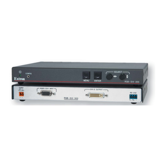
Installation, cont’d Front Panel Layout The illustration below shows the front panel features and controls of the RGB-HDMI 300 (upper image) and RGB-DVI 300 (lower image): ADJUST CONFIG MENU ENTER RGB - HDMI 300 ADJUST CONFIG MENU ENTER RGB - DVI 300 Front panel layout LED indicator —... -
Page 17: Rear Panel Layout
15-pin HD connector. Digital signal output — Both models output digital signals. The RGB-DVI 300 outputs a DVI-D signal through a female DVI-I connector; the RGB-HDMI 300 outputs an HDMI signal through a female HDMI connector. - Page 18 Installation, cont’d RGB-DVI 300 and RGB-HDMI 300 • Installation...
-
Page 19: Chapter Three • Operation
RGB-DVI 300 and RGB-HDMI 300 Chapter Three Operation Input and Output Configuration Front Panel Connections and Controls Rear Panel Connections... -
Page 20: Input And Output Configuration
Default values for the detected input rate for total pixels, active pixels, and active lines are shown with an asterisk (*) in the on-screen display. RGB-DVI 300 and RGB-HDMI 300 • Operation... -
Page 21: Output Signal
0 to 127. The default setting is 64. Contrast — Contrast adjusts the difference between the input's darkest and brightest settings, on a scale from 0 to 127 (the default is 64). RGB-DVI 300 and RGB-HDMI 300 • Operation... - Page 22 Operation, cont’d RGB-DVI 300 and RGB-HDMI 300 • Operation...
- Page 23 RGB-DVI 300 and RGB-HDMI 300 • Operation...
-
Page 24: Other
Reset — There are two types of reset. Firmware reset returns all options, including the firmware to the factory defaults. Factory reset returns all image options to the factory defaults but keeps the current version of the firmware. For more information, see page 3-17. RGB-DVI 300 and RGB-HDMI 300 • Operation... -
Page 25: Front Panel Connections And Controls
Front Panel Connections and Controls The front panels of both the RGB-DVI 300 and the RGB-HDMI 300 have a green/amber LED indicator, a config port, menu and enter buttons, and two rotary encoders (see page 2-6). LED indicator A green light indicates the unit is receiving power and has an active video input. -
Page 26: Front Panel Menu Controls
The menu and enter buttons and rotary encoders are used to configure and optimize the unit's input and output signals. The menus for the RGB-DVI 300 and RGB-HDMI 300 are On-Screen Dipslay (OSD). To see menu selections, a display device must be attached to the output of the video scaler/converter. - Page 27 Press the Menu button to open the menu. A header that identifies the model and the top-level menu appears on the output display. In all following figures the RGB-DVI 300 has been used in the illustrations. Apart from the heading, the RGB-HDMI 300 menu is identical in all respects.
-
Page 28: Auto Image
This feature initiates a one-time auto image on the current input. Auto image can also be set globally, using the Advanced Configuration menu, to size and center each new input rate, automatically. RGB-DVI 300 and RGB-HDMI 300 • Operation 3-10... -
Page 29: Picture Controls
User presets are a user defined set of picture control settings for up to three commonly used aspect ratio settings. When picture controls and input configuration have been set, as described elsewhere in this section, the current values for contrast, RGB-DVI 300 and RGB-HDMI 300 • Operation 3-11... - Page 30 (the same values saved by user presets) and input configuration values (input type, total pixels, horizontal and vertical starts, horizontal and vertical active areas and phase). The exact settings of a source are saved and can be recalled each RGB-DVI 300 and RGB-HDMI 300 • Operation 3-12...
-
Page 31: Input Configuration
(depends on input resolution) ± 512 Phase Horizontal start Vertical start Active Pixels default value (depends on input resolution) ± 512 Active Lines default value (depends on input resolution) ± 256 RGB-DVI 300 and RGB-HDMI 300 • Operation 3-13... -
Page 32: Output Configuration
The output configuration is used to select a scaler output rate from the various available resolution and refresh rates. Both the RGB-DVI 300 and the RGB-HDMI 300 have a large range of combinations of resolution and refresh rate (see table on pages 3-4 and 3-5). -
Page 33: Advanced Configuration
Test pattern can be set to Color Bars, grayscale, crosshatch, alternating pixels, crop, four different aspect ratios, or off. These patterns are used to configure the output signal. RGB-DVI 300 and RGB-HDMI 300 • Operation 3-15... - Page 34 However, if the user adjusts the input manually or carries out an Auto Image, the new parameters is automatically stored by the Auto Memory function. RGB-DVI 300 and RGB-HDMI 300 • Operation 3-16...
- Page 35 Menu button, the output rate toggles to 720p at 60 Hz. These values were chosen because most PC monitors with a digital input will accept an XGA signal and most other consumer/professional displays will accept 720p. RGB-DVI 300 and RGB-HDMI 300 • Operation 3-17...
-
Page 36: Rear Panel Connections
Operation, cont’d Rear Panel Connections The rear panels of both the RGB-DVI 300 and the RGB-HDMI 300 have a power input, RGB/HDTV YUV signal input, digital signal output, and RS-232 port. Power Connections Connect the captive screw connector from the supplied 12 VDC power supply into the power receptacle. -
Page 37: Input Connections
RGBS RGsB, RsGsBs, Component Output Connections Use the Female DVI-I connector (RGB-DVI 300) or the Female HDMI connector (RGB-HDMI 300) to pass the output signal to the display device. DVI-D OUTPUT Rear panel DVI connector (RGB-DVI 300) Although the RGB-DVI 300 has a rear panel DVI-I connector, the output signal is DVI-D (digital only). - Page 38 Likewise, if the captive screw port is in use, the config port on the front panel must be disconnected from the computer or other control device. RGB-DVI 300 and RGB-HDMI 300 • Operation 3-20...
-
Page 39: Chapter Four • Controls
RGB-DVI 300 and RGB-HDMI 300 Chapter Four Controls Introduction to SIS ™ Symbols used in this manual Command/response table for SIS commands Signal Processing Products Control Program... -
Page 40: Introduction To Sis
(CR/LF = ), which signals the end of the response character string. When the RGB-DVI 300 or RGB-HDMI 300 is first switched on, depending on the model, it sends the message: (c) COPYRIGHT 2009, EXTRON ELECTRONICS, RGB-DVI 300, V x.xx, 60-906-01... -
Page 41: Symbols Used In This Manual
— Active lines value for high resolution video is the default value ± 256 (the default value depends on the the input resolution) — Picture adjustment (contrast, brightness, and detail): from 0 to 127 (default = 64) RGB-DVI 300 and RGB-HDMI 300 • Serial Communications... - Page 42 — Ouput format (color space) 0 = RGB (default) 1 = YUV — User presets: from 1 to 3 — Input presets: from 1 to 16 Input presets are available only through SIS commands. RGB-DVI 300 and RGB-HDMI 300 • Serial Communications...
-
Page 43: Error Messages
E17 = Invalid command for signal type E13 = Invalid parameter E22 = Busy If the RGB-DVI 300 or RGB-HDMI 300 does not support or recognize the entered commands, nothing will happen and no response is issued. RGB-DVI 300 and RGB-HDMI 300 • Serial Communications... -
Page 44: Command/Response Table For Sis Commands
Command/response table for SIS commands Command ASCII Command Response Additional Description (host to unit) (unit to host) Input video format Set Format Typ1* Sets input format 1 = RGB (default) 2 = YUV View Format View current video input format. Auto image Enable 1*1A... - Page 45 Command ASCII Command Response Additional Description (host to unit) (unit to host) Horizontal start Set a horizontal start value Set the horizontal location of the first active HSRT Hsrt from 0 to 255 pixel ) for active input. Increment horizontal start value Increases the horizontal start value by 1.
- Page 46 Command ASCII Command Response Additional Description (host to unit) (unit to host) Total pixels Specify a value Adjust total number of pixels to specified TPIX Tpix value for active input. Total pixels = default value ± 512 Increment total number of pixels Increases total number of pixels by 1.
- Page 47 Command ASCII Command Response Additional Description (host to unit) (unit to host) Decrement number of active Decreases number of active lines by 1. -ALIN Alin lines View number of active lines View number of active lines. ALIN Alin Video mute Enable mute Blanks selected input.
- Page 48 Command ASCII Command Response Additional Description (host to unit) (unit to host) Detail filter EX1) X1)] Specify detail level HDET Hdet Sets detail level to (from 0 to 127). X1)] Increment the detail level Increases the detail level by 1. +HDET Hdet X1)]...
- Page 49 Command ASCII Command Response Additional Description (host to unit) (unit to host) Horizontal size EX1@ X1@] Specify horizontal size HSIZ Hsiz Sets horizontal sizing to (depends on output resolution). X1@] Increment horizontal size Increases horizontal sizing by 1. +HSIZ Hsiz X1@] Decrement horizontal size Decreases horizontal sizing by 1.
- Page 50 Command ASCII Command Response Additional Description (host to unit) (unit to host) Output scaler rate EX1% X1^] Set output rate RATE Rate Selects scaler resolution and refresh rate (see tables on page 4-4). An incompatible combination of resolution and refresh rate results in an error message.
- Page 51 Command ASCII Command Response Additional Description (host to unit) (unit to host) Input presets X1(] Save preset Saves current settings as memory preset 2Spr (1 to 16). The final character of the command is a comma (,). X1(] Recall preset 2Rpr Recalls input preset (1 to 16).
- Page 52 Command ASCII Command Response Additional Description (host to unit) (unit to host) Auto memories Enable Sets auto memory on. Previous settings for 1AMEM Amem1 incoming signals are auto recalled. Disable Sets auto memory to off. Defaults to input 0AMEM Amem0 lookup table values to configure input.
- Page 53 Command ASCII Command Response Additional Description (host to unit) (unit to host) Front panel security lockout (executive mode) Enable Enables front panel security lockout Exe1 (executive mode; limits front panel adjustments). Disable Disables front panel security lockout Exe0 (restores ability to make adjustments from font panel).
- Page 54 Query firmware version (full) View the full firmware version. x.xx.xxxx Query part number View the unit part number. xx-xxx-xx (RGB-DVI 300 is 60-906-01; RGB-HDMI 300 is 60-907-01) X2$] View internal temperature View the internal temperature of the unit • 20STAT Stat20 (in degrees Celsius).
-
Page 55: Signal Processing Products Control Program
Signal Processing Products Control Program All the features of the RGB-DVI 300 and RGB-HDMI 300 that can be controlled by SIS commands, can also be controlled by a computer that is running the Signal Processing Products Control Program (SPPCP). Installing the SPPCP The control program is available on the disk provided with the RGB-DVI 300 or RGB-HDMI 300. - Page 56 For complete instructions on controlling the RGB-DVI 300 or RGB-HDMI 300 using the SPPCP, refer to the Help File, which can be selected from the Help drop-down menu or by pressing the F1 key. RGB-DVI 300 and RGB-HDMI 300 • Serial Communications 4-18...
-
Page 57: Firmware Upgrades
Firmware Upgrades Firmware for the RGB-DVI 300 or RGB-HDMI 300 can be upgraded using the Extron Firmware Loader utility by following the steps below: 1. Power on the scaler and a computer with internet access. 2. Connect the computer to the video scaler through either the front Config port or the rear RS-232 captive screw connectors. - Page 58 3 minutes. During the firmware upload, the front panel LED and video output are disabled. 10. When the "Transfer Complete!" message appears, click the Exit button and exit the Firmware Loader. RGB-DVI 300 and RGB-HDMI 300 • Serial Communications 4-20...
-
Page 59: Appendix A • Reference Information
RGB-DVI 300 and RGB-HDMI 300 A ppendix A Reference Information Specifications Included Parts Accessories... - Page 60 Video Output Number/signal type RGB-DVI 300...... 1 single link DVI-D RGB-HDMI 300 ....1 single link HDMI Connectors RGB-DVI 300...... 1 female DVI-I (digital output only) RGB-HDMI 300 ....I female HDMI RGB-DVI 300 and RGB-HDMI 300 • Reference Information...
- Page 61 Baud rate and protocol ....9600, 8 data bits, 1 stop bit, no parity Serial control pin configurations. 1 = TX, 2 = RX, 3 = GND Program control......Extron's control/configuration program for Windows ® Extron's Simple Instruction Set (SIS ™ RGB-DVI 300 and RGB-HDMI 300 • Reference Information...
- Page 62 EMI/EMC ......CE, C-tick, FCC Class A, ICES, VCCI Environmental ....Complies with the appropriate requirements of WEEE MTBF..........30,000 hours Warranty......... 3 years parts and labor All nominal levels are ±10% Specificatons are subject to change without notice. RGB-DVI 300 and RGB-HDMI 300 • Reference Information...
- Page 63 RSU 126 (1U 6" deep rack shelf kit) 60-190-10 RSB 126 (1U 6" deep basic rack shelf) 60-604-10 MBU 125 (under desk mounting kit) 70-077-01 MBD 129 (through desk mounting kit) 70-077-02 RGB-DVI 300 and RGB-HDMI 300 • Reference Information...
- Page 64 Reference Information, cont’d RGB-DVI 300 and RGB-HDMI 300 • Reference Information...
- Page 65 RGB-DVI 300 and RGB-HDMI 300 • Reference Information...
- Page 66 Reference Information, cont’d RGB-DVI 300 and RGB-HDMI 300 • Reference Information...
- Page 67 In no event will Extron Electronics be liable for direct, indirect, or consequential damages resulting from any defect in this product even if Extron Electronics has been advised of such damage.
- Page 68 Inside USA / Canada Only Inside Europe Only Inside Asia Only Inside China Only Inside USA / Canada Only +1.919.863.1794 +31.33.453.4040 +65.6383.4400 +86.21.3760.1568 +1.714.491.1500 +1.919.863.1797 FAX +31.33.453.4050 FAX +65.6383.4664 FAX +86.21.3760.1566 FAX +1.714.491.1517 FAX © 2009 Extron Electronics. All rights reserved.
Need help?
Do you have a question about the RGB-DVI 300 and is the answer not in the manual?
Questions and answers