Kannad 406 AF-COMPACT Installation Manual
Emergency locator transmitter
Hide thumbs
Also See for 406 AF-COMPACT:
- Quick installation manual (9 pages) ,
- Service letter (4 pages) ,
- Installation manual (44 pages)
Table of Contents

Related Manuals for Kannad 406 AF-COMPACT


Summary of Contents for Kannad 406 AF-COMPACT
- Page 1 DOC06006D Ref. 0141922D Emergency Locator Transmitters INSTALLATION MANUAL OPERATION MANUAL INSPECTION LOG KANNAD 406 AF-COMPACT P/N : S1840501-02 Pack ELT KANNAD AF-COMPACT TP PAGE : 1 Revision 03 Date of rev. FEB 01/2008 First issue: FEB 01/2007...
- Page 3 INSTALLATION MANUAL OPERATION MANUAL INSPECTION LOG KANNAD 406 AF-COMPACT RECORD OF REVISIONS REV. Nb REVISION DATE INSERTION DATE FEB 01/2007 J.S. FEB 01/2007 SEP 04/2007 SEP 04/2007 J.S. SEP 05/2007 SEP 05/2007 J.S. FEB 01/2008 FEB 01/2008 J.S. ROR PAGE: 1...
- Page 4 INSTALLATION MANUAL OPERATION MANUAL INSPECTION LOG KANNAD 406 AF-COMPACT RECORD OF REVISIONS PAGE INTENTIONALLY LEFT BLANK ROR PAGE: 2 FEB 01/2008...
- Page 5 INSTALLATION MANUAL OPERATION MANUAL INSPECTION LOG KANNAD 406 AF-COMPACT LIST OF EFFECTIVE PAGES SUBJECT PAGE DATE Title Page FEB 01/2008 Record of Revisions FEB 01/2008 FEB 01/2008 List of Effective Pages FEB 01/2008 FEB 01/2008 Table of Contents FEB 01/2008...
- Page 6 INSTALLATION MANUAL OPERATION MANUAL INSPECTION LOG KANNAD 406 AF-COMPACT LIST OF EFFECTIVE PAGES SUBJECT PAGE DATE FEB 01/2008 FEB 01/2008 FEB 01/2008 FEB 01/2008 FEB 01/2008 FEB 01/2008 FEB 01/2008 FEB 01/2008 FEB 01/2008 FEB 01/2008 FEB 01/2008 FEB 01/2008...
- Page 7 INSTALLATION MANUAL OPERATION MANUAL INSPECTION LOG KANNAD 406 AF-COMPACT LIST OF EFFECTIVE PAGES SUBJECT PAGE DATE FEB 01/2008 Check FEB 01/2008 FEB 01/2008 FEB 01/2008 FEB 01/2008 Troubleshooting FEB 01/2008 FEB 01/2008 Schematics and Diagrams FEB 01/2008 FEB 01/2008 FEB 01/2008...
-
Page 8: Lep Page
INSTALLATION MANUAL OPERATION MANUAL INSPECTION LOG KANNAD 406 AF-COMPACT LIST OF EFFECTIVE PAGES SUBJECT PAGE DATE FEB 01/2008 FEB 01/2008 FEB 01/2008 FEB 01/2008 FEB 01/2008 FEB 01/2008 FEB 01/2008 FEB 01/2008 FEB 01/2008 LEP PAGE: 4 FEB 01/2008... -
Page 9: Table Of Contents
Description ......................1 World coverage with the COSPAS-SARSAT system ..........2 Environmental improvements of ELTs ..............2 G-Switch (shock detectors) ..................2 KANNAD 406 ELTs Presentation ............3 LINE REPLACEABLE UNITS ............... 4 Transmitter ......................4 Bracket ........................5 Remote Control Panel ................... 5 Outside antenna .................... - Page 10 INSTALLATION MANUAL OPERATION MANUAL INSPECTION LOG KANNAD 406 AF-COMPACT TABLE OF CONTENTS Electrical Interfaces ..................111 RC200 Technical Specifications ................ 112 Photovoltaic Relay ..................112 Environmental specifications ................112 Antennas Technical Specifications ..............113 ANT 200 ......................113 ANT 300 ......................113 Equipment limitations ................
- Page 11 INSTALLATION MANUAL OPERATION MANUAL INSPECTION LOG KANNAD 406 AF-COMPACT TABLE OF CONTENTS Connection ...................... 212 ELT Connection ................213 First power up ................... 213 Removal .................... 214 CHECK ....................301 Self-test ..................... 301 Periodicity ......................301 Self-test procedure .................... 301 Operational tests ................
- Page 12 INSTALLATION MANUAL OPERATION MANUAL INSPECTION LOG KANNAD 406 AF-COMPACT TABLE OF CONTENTS Measurement of output powers, frequencies and verification of digital message 603 Battery pack replacement ................604 Check of 121.5 MHz frequency ............... 609 Battery replacement requirements ..............610 Periodic Inspection Log ............
-
Page 13: Introduction
The KANNAD 406 AF-COMPACT has been designed to satisfy the requirements of general aviation pilots, built on the long experience of KANNAD ELTs in 406 MHz technology in aviation, maritime and land distress beacons. The instructions in this manual provide the information necessary for the installation and the operation of KANNAD 406 AF-COMPACT ELT. -
Page 14: Warranty
The equipment is warranted against all material or manufacturing defect for a period of two years from the date of installation on the aircraft or thirty months for the date of shipment from KANNAD S.A.S. Z.I. des Cinq Chemins BP23, 56520 Guidel, France, whichever occur first. -
Page 15: System Overview
INSTALLATION MANUAL OPERATION MANUAL INSPECTION LOG KANNAD 406 AF-COMPACT SYSTEM OVERVIEW 1. COSPAS-SARSAT System A. Description Launched in the early eighties by the four founder countries (Canada, France, Russia, USA), the COSPAS-SARSAT system provides satellite aid to search and rescue (SAR) operations for maritime, aeronautical and terrestrial vehicles anywhere in the world. -
Page 16: World Coverage With The Cospas-Sarsat System
INSTALLATION MANUAL OPERATION MANUAL INSPECTION LOG KANNAD 406 AF-COMPACT B. World coverage with the COSPAS-SARSAT system The major improvement is the use of the COSPAS-SARSAT system for processing aeronautical emergencies. The difference with the 121.5 is that the 406 MHz transmission carries digital data which enable the identification of the aircraft in distress and facilitate SAR operation (type of the aircraft, number of passengers, type of emergency). -
Page 17: Kannad 406 Elts Presentation
KANNAD 406 AF-COMPACT 2. KANNAD 406 ELTs Presentation The KANNAD 406 AF-COMPACT belongs to the AF type of ELTs which are permanently attached to an aircraft. The KANNAD 406 AF-COMPACT is designed to be installed on fixed wing aircraft or helicopters. -
Page 18: Line Replaceable Units
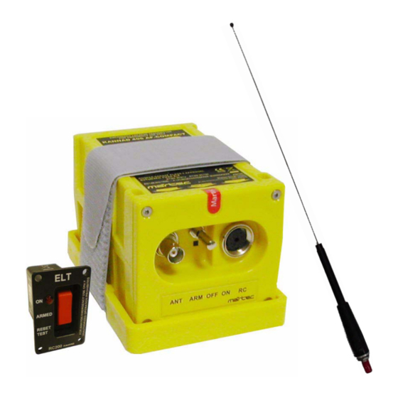
KANNAD 406 AF-COMPACT 3. LINE REPLACEABLE UNITS A. Transmitter The KANNAD 406 AF-COMPACT is an ELT designed to be installed onboard aircraft to transmit a distress signal on frequencies: • 406 MHz (COSPAS-SARSAT frequency) for precise pinpointing and identification of the aircraft in distress. -
Page 19: Bracket
The bracket installed near the tail is designed to fix the ELT with a Velcro® strap. This enables quick removal of the ELT for maintenance or exchange. Figure 4: KANNAD 406 AF-COMPACT with Mounting Bracket C. Remote Control Panel An RC200 remote control panel is available for installation in the cockpit in order to enable the pilot to monitor and control the ELT status. -
Page 20: Outside Antenna
Connection to the ELT will be carried out with a 50 Ohm coaxial cable (RG58 for example) ended with a male BNC connector. IMPORTANT NOTICE: KANNAD recommends a cable with radio electric properties similar to those of a RG58 cable. -
Page 21: System Functional Description And Operation
(thanks to a shock sensor) or manually (thanks to a switch on the transmitter itself or on the RC200 Remote Control Panel). The KANNAD 406 AF-COMPACT is designed to transmit on two frequencies (121.5 and 406 MHz). The 121.5 Mhz is mainly used for homing in the final stages of the rescue operations. -
Page 22: Controls & Connectors
INSTALLATION MANUAL OPERATION MANUAL INSPECTION LOG KANNAD 406 AF-COMPACT B. Controls & Connectors The following controls are to be found on the ELT front panel (from left to right): 3-position switch ARM/OFF/ON; Visual indicator (red); DIN 12 socket for connection to Remote Control Panel, programming dongle or programming equipment;... -
Page 23: Working Mode Information
INSTALLATION MANUAL OPERATION MANUAL INSPECTION LOG KANNAD 406 AF-COMPACT C. Working mode information The KANNAD 406 AF-COMPACT has 4 different modes: • Off. • Self-test (temporary mode). • Armed (standby mode to enable automatic activation by the shock sensor or by the remote control panel). - Page 24 INSTALLATION MANUAL OPERATION MANUAL INSPECTION LOG KANNAD 406 AF-COMPACT It is recommended to test the ELT regularly in order to detect any possible failure (Refer to A. Periodicity, page 301). The number of self-tests carried out is recorded. This information is available when the ELT is connected to a programming and test equipment (PR600).
-
Page 25: Autonomy
1st of January 2003. The duration of the 121.5 transmissions is over 48 hours at -20°C. Unlike other ELTs, the 406 MHz transmission of KANNAD 406 AF-COMPACT is not stopped after 24 hours and 406 MHz transmission is continuing beyond 48 hours. -
Page 26: Transmitter Technical Characteristics
INSTALLATION MANUAL OPERATION MANUAL INSPECTION LOG KANNAD 406 AF-COMPACT E. Transmitter Technical characteristics (1) Mechanical characteristics The ELT housing is to be installed on a Mounting Bracket (P/N S1840502- 01). (2) Material - Material: Polycarbonate. - Treatment: Light yellow color (RAL 1018), Fire classification M0. - Page 27 INSTALLATION MANUAL OPERATION MANUAL INSPECTION LOG KANNAD 406 AF-COMPACT (a) J1 DIN 12 socket J1 is dedicated for connection to the Remote Control Panel, to a Programming or Maintenance Dongles and/or to a programming equipment (PR600). IMPORTANT: Shielded cables are recommended. The required wires are AWG24.
-
Page 28: Transmitter Technical Specifications
INSTALLATION MANUAL OPERATION MANUAL INSPECTION LOG KANNAD 406 AF-COMPACT F. Transmitter Technical Specifications TYPE G-SWITCH SENSOR • Two-frequency ELT Mechanical G-switch sensor compliant (121.5 / 406.028 MHz) with EUROCAE ED62 specifications • Automatic fixed BATTERY • COSPAS-SARSAT Category II KIT BAT200, P/N: S1840510-01 (-20°C to +55°C). -
Page 29: Remote Control Panel Rc200 Functional Description
The RC200 Remote Control Panel is designed to be installed in the cockpit to enable the pilots to control the ELT onboard. The RC200 enables the remote control of the primary functions of the KANNAD Emergency Locator Transmitters (Manual activation, Reset, Test) as well as visual monitoring. -
Page 30: Rc200 Technical Characteristics
INSTALLATION MANUAL OPERATION MANUAL INSPECTION LOG KANNAD 406 AF-COMPACT C. RC200 Working mode information The RC200 enables remote control and remote monitoring of the KANNAD 406 AF-COMPACT provided that the ELT switch is in armed position. (1) Remote Control Remote control is accomplished through a 3-position switch: - ON (transmission) enables manual activation of the ELT. - Page 31 (3) Electrical Interfaces A single male 9-pin D-SUB connector (J1) enables to connect the RC200 remote control panel to the KANNAD 406 AF-COMPACT with a 3-wire cable (AWG 24, shielded recommended). On the ELT side, the wires are soldered to a male DIN 12 connector.
-
Page 32: Rc200 Technical Specifications
INSTALLATION MANUAL OPERATION MANUAL INSPECTION LOG KANNAD 406 AF-COMPACT Receptacle Standard designation D-SUB - Male - 9 Pts Number of pins Locking device Inserts, Threaded UNC 4-40 KANNAD 0127012 Table 3: D-SUB 9 Pts Male Characteristics Mating connector Standard designation... -
Page 33: Antennas Technical Specifications
INSTALLATION MANUAL OPERATION MANUAL INSPECTION LOG KANNAD 406 AF-COMPACT F. Antennas Technical Specifications (1) ANT 200 ANT200 is a whip dual frequency antenna for aircraft up to 250 kts. - Frequencies: 121.5 / 406 MHz. - Impedance: 50 ohms. - VSWR: •... -
Page 34: Activation
INSTALLATION MANUAL OPERATION MANUAL INSPECTION LOG KANNAD 406 AF-COMPACT 4. Activation A. Standby mode for automatic activation In order to be automatically activated by the crash sensor, the ELT must be in standby mode. This mode is mandatory during the flight. We recommend to switch off the ELT only when the aircraft is parked for a long period or for a maintenance operation. -
Page 35: Installation / Removal
INSTALLATION MANUAL OPERATION MANUAL INSPECTION LOG KANNAD 406 AF-COMPACT INSTALLATION / REMOVAL 1. Registration A. General The ELT must be registered prior to installation onboard. When a 406 MHz ELT is installed in an aircraft, it is imperative that the aircraft owner register the ELT. -
Page 36: Registration In Canada
INSTALLATION MANUAL OPERATION MANUAL INSPECTION LOG KANNAD 406 AF-COMPACT Registration Decal by postal mail. This decal is to be affixed to the beacon and should be placed in such a way that it is clearly visible. If for some reason you do not receive the registration decal within two weeks, please call NOAA toll- free at: 1-888-212-SAVE (7283) or 301-817-4515. -
Page 37: Programming
KANNAD 406 AF-COMPACT 2. Programming A. "Pin programming" option The KANNAD 406 AF-COMPACT offers pin-programming capabilities to facilitate maintenance operations especially in the case of removals and/or replacement. A special DIN 12 connector with a Serial Memory Module (called "Programming Dongle") is connected to the ELT when installed onboard. -
Page 38: Elt Installation
INSTALLATION MANUAL OPERATION MANUAL INSPECTION LOG KANNAD 406 AF-COMPACT 3. ELT Installation A. ELT and bracket installation recommendations The ELT shall not be installed within 60cm (2 ft) of a compass or flux gate. Use cable of loss ≤ 1dB. -
Page 39: Bracket Installation Procedure
"Flight direction" label pointed towards the front of the aircraft. (2) Helicopters The standard version of the KANNAD 406 AF-COMPACT may be installed on helicopter. The ELT unit should be mounted: • with the front face connectors pointing downwards at a 45° angle to the yaw axis;... - Page 40 INSTALLATION MANUAL OPERATION MANUAL INSPECTION LOG KANNAD 406 AF-COMPACT • Drill 4 holes Ø 6 mm in the aircraft structure according to "Drilling mask" (Refer to § 2. ELT Drilling Mask, page 502). Inner holes (1, 2, 3, 4) shall be preferred.
-
Page 41: Elt Installation Procedure
C. ELT installation procedure Mount the transmitter on the bracket "Flight direction" arrow pointed towards the front of the aircraft (Figure 202: KANNAD 406 AF- COMPACT, axis of installation). Slide the self-stripping strap through the buckle. Ensure the buckle is correctly positioned (indifferently on right or left side of ELT) regarding the horizontal center line of ELT as shown Detail A. -
Page 42: Antenna Installation
INSTALLATION MANUAL OPERATION MANUAL INSPECTION LOG KANNAD 406 AF-COMPACT 4. Antenna Installation Use only whip (ANT200) or rod (ANT 300) approved antennas. A. Antenna Installation Recommendations (1) FAA Recommendations Installation must be made by qualified personnel in accordance with FAA regulations. -
Page 43: Antenna Installation Procedure
INSTALLATION MANUAL OPERATION MANUAL INSPECTION LOG KANNAD 406 AF-COMPACT be subjected to any tensile load and should be tied loosely to the tether. C. Antenna installation procedure Ensure that the antenna mounting location meets the requirements as described § B. Antenna mounting location. -
Page 44: Rcp Installation
INSTALLATION MANUAL OPERATION MANUAL INSPECTION LOG KANNAD 406 AF-COMPACT 5. RCP installation A. RCP Installation Recommendations The RC200 shall be readily accessible from the pilot’s normal seated position. If possible, the RC200 should be installed in the cockpit in an area that is not directly exposed to sun rays. -
Page 45: Installation Below The Instrument Panel
INSTALLATION MANUAL OPERATION MANUAL INSPECTION LOG KANNAD 406 AF-COMPACT (2) Installation below the instrument panel Figure 206: Installation of RC200 with mounting tray Determine RC200 location below the instrument panel (be sure the location meets the requirements established in RTCA-DO-204). -
Page 46: Connection
INSTALLATION MANUAL OPERATION MANUAL INSPECTION LOG KANNAD 406 AF-COMPACT (3) Connection Fabricate a 3-wire bundle (AWG 24, shielded preferred) long enough to reach between the ELT installation location and the cockpit panel RCP location. Figure 207: Wiring of 3-wire bundle Slide heat-shrinkable sleeves on both sides of each wire. -
Page 47: Elt Connection
INSTALLATION MANUAL OPERATION MANUAL INSPECTION LOG KANNAD 406 AF-COMPACT 6. ELT Connection Connect the cable of the outside antenna to the BNC connector of the front panel. Connect the DIN12 connector of the Remote Control Panel cable to the DIN 12 socket of the front panel. -
Page 48: Removal
INSTALLATION MANUAL OPERATION MANUAL INSPECTION LOG KANNAD 406 AF-COMPACT 8. Removal Switch the ELT to OFF. Disconnect the outside antenna from the BNC connector of the ELT. Disconnect the DIN 12 Connector of Remote Control Panel 3-wire bundle from the DIN12 socket of the ELT. -
Page 49: Check
INSTALLATION MANUAL OPERATION MANUAL INSPECTION LOG KANNAD 406 AF-COMPACT CHECK 1. Self-test A. Periodicity It is recommended by the manufacturer to test the ELT to detect any possible failure. Operational check must be performed regularly by a pilot or maintenance personnel from the cockpit (Remote Control Panel). -
Page 50: Operational Tests
INSTALLATION MANUAL OPERATION MANUAL INSPECTION LOG KANNAD 406 AF-COMPACT 2. Operational tests These tests must be performed by maintenance personnel when performing the first power up procedure or to check RCP monitoring and control (Refer to B. RCP operational tests) or transmitter (Refer to C. -
Page 51: And 121.5 Mhz Transmission Test
INSTALLATION MANUAL OPERATION MANUAL INSPECTION LOG KANNAD 406 AF-COMPACT C. 406 and 121.5 MHz transmission test NOTE: Transmissions tests only provide the aircraft operator with an indication that the ELT is transmitting; however, a positive result cannot be interpreted as meaning that the ELT meets all operational parameters. - Page 52 INSTALLATION MANUAL OPERATION MANUAL INSPECTION LOG KANNAD 406 AF-COMPACT PAGE INTENTIONALLY LEFT BLANK PAGE: 304 FEB 01/2008...
-
Page 53: Troubleshooting
INSTALLATION MANUAL OPERATION MANUAL INSPECTION LOG KANNAD 406 AF-COMPACT TROUBLESHOOTING 1. General Procedure for fault isolation onboard uses the indicator light of the ELT’s front panel. This indicator light is activated by a self-test capability within the ELT. 2. Faults on Self-test A. - Page 54 INSTALLATION MANUAL OPERATION MANUAL INSPECTION LOG KANNAD 406 AF-COMPACT PAGE INTENTIONALLY LEFT BLANK PAGE: 402 FEB 01/2008...
-
Page 55: Schematics & Diagrams
INSTALLATION MANUAL OPERATION MANUAL INSPECTION LOG KANNAD 406 AF-COMPACT SCHEMATICS & DIAGRAMS 1. ELT Outline Dimensions PAGE: 501 FEB 01/2008... -
Page 56: Elt Drilling Mask
INSTALLATION MANUAL OPERATION MANUAL INSPECTION LOG KANNAD 406 AF-COMPACT 2. ELT Drilling Mask PAGE: 502 FEB 01/2008... -
Page 57: Rc200 Outline Dimensions
INSTALLATION MANUAL OPERATION MANUAL INSPECTION LOG KANNAD 406 AF-COMPACT 3. RC200 Outline Dimensions PAGE: 503 FEB 01/2008... -
Page 58: Rc200 Drilling Mask
INSTALLATION MANUAL OPERATION MANUAL INSPECTION LOG KANNAD 406 AF-COMPACT 4. RC200 Drilling Mask PAGE: 504 FEB 01/2008... -
Page 59: Ant200 Outline Dimensions
INSTALLATION MANUAL OPERATION MANUAL INSPECTION LOG KANNAD 406 AF-COMPACT 5. ANT200 Outline Dimensions PAGE: 505 FEB 01/2008... -
Page 60: Ant300 Outline Dimensions
INSTALLATION MANUAL OPERATION MANUAL INSPECTION LOG KANNAD 406 AF-COMPACT 6. ANT300 Outline Dimensions PAGE: 506 FEB 01/2008... -
Page 61: Wiring
INSTALLATION MANUAL OPERATION MANUAL INSPECTION LOG KANNAD 406 AF-COMPACT 7. Wiring PAGE: 507 FEB 01/2008... - Page 62 INSTALLATION MANUAL OPERATION MANUAL INSPECTION LOG KANNAD 406 AF-COMPACT PAGE INTENTIONALLY LEFT BLANK PAGE: 508 FEB 01/2008...
-
Page 63: Servicing
INSTALLATION MANUAL OPERATION MANUAL INSPECTION LOG KANNAD 406 AF-COMPACT SERVICING 1. Maintenance Schedule Periodic inspection and battery replacement can only be carried out by an accredited PART 145 or FAR 145 maintenance station. A. Periodic inspection Note: (if required by the relevant Civil Aviation Authority). -
Page 64: Transmitted Signals
INSTALLATION MANUAL OPERATION MANUAL INSPECTION LOG KANNAD 406 AF-COMPACT (3) Transmitted signals - Perform a self-test from the ELT and RCP as explained § B. Self-test procedure, page 301. The following parameters are checked during self-test: • Battery voltage. • 121.5 MHz / 406.028 MHz transmission power. -
Page 65: Year Inspection
KANNAD suggests to measure output power, frequencies and check the digital message using the WS TECHNOLOGY BT100AVTRIPLE Cospas-Sarsat decoder (this decoder can be supplied by KANNAD under P/N 0140956) or AEROFLEX IFR 4000 NAV/COMM Ramp Test Set. Other beacons testers can be used if they are capable to fill the functions required to measure power and frequencies of 121.5 and 406 MHz transmitters and to decode the digital... - Page 66 INSTALLATION MANUAL OPERATION MANUAL INSPECTION LOG KANNAD 406 AF-COMPACT manual included with the decoder. • Measurement of output powers - Perform a self-test (Refer to § B. Self-test procedure, page 301). Read value of 121.5 MHz: 100 to 400 mW (20 dBm to 26 dBm).
- Page 67 INSTALLATION MANUAL OPERATION MANUAL INSPECTION LOG KANNAD 406 AF-COMPACT Figure 201: Battery Pack Disassembly / Reassembly PAGE: 605 FEB 01/2008...
- Page 68 INSTALLATION MANUAL OPERATION MANUAL INSPECTION LOG KANNAD 406 AF-COMPACT - Removal of battery pack Refer to Figure 201: Battery Pack Disassembly / Reassembly • Remove and discard the 4 securing screws and nuts from the ELT front panel. • Carefully extract the ELT front panel from the housing up to reach the battery connector.
- Page 69 INSTALLATION MANUAL OPERATION MANUAL INSPECTION LOG KANNAD 406 AF-COMPACT Figure 202: Recording of Maintenance Tasks PAGE: 607 FEB 01/2008...
- Page 70 INSTALLATION MANUAL OPERATION MANUAL INSPECTION LOG KANNAD 406 AF-COMPACT - Protecting the battery pack NOTE: A foam is supplied with the battery kit. This foam, composed of four leaves attached together and covered by adhesive , is used to protect the battery pack when installed in the housing.
- Page 71 INSTALLATION MANUAL OPERATION MANUAL INSPECTION LOG KANNAD 406 AF-COMPACT - Battery pack reinstallation Refer to Figure 201: Battery Pack Disassembly / Reassembly • Insert the desiccant capsule supplied with the kit into the hole of the foam stuck on the front panel.
- Page 72 [SAFT-FRIWO , Lithium Manganese Dioxide, 2 x M20 (D-type) cells] PLEASE CONTACT YOUR LOCAL DISTRIBUTOR KANNAD refuse all responsibility and invalidate all warranty should other packs be installed. Battery available from KANNAD or any KANNAD distributor or dealer. KANNAD Z.I. des Cinq Chemins BP23 56520 GUIDEL - FRANCE...
- Page 73 INSTALLATION MANUAL OPERATION MANUAL INSPECTION LOG KANNAD 406 AF-COMPACT 2. Periodic Inspection Log Type of inspection : Periodic Battery change Repair.. Other Operations carried out (*) : Next recommended inspection date : _ _ / _ _ _ _ Next planned battery replacement (mandatory) date : _ _ / _ _ _ _...
- Page 74 INSTALLATION MANUAL OPERATION MANUAL INSPECTION LOG KANNAD 406 AF-COMPACT 3. Periodic Inspection Log Type of inspection : Periodic Battery change Repair.. Other Operations carried out (*) : Next recommended inspection date : _ _ / _ _ _ _ Next planned battery replacement (mandatory) date : _ _ / _ _ _ _...
- Page 75 INSTALLATION MANUAL OPERATION MANUAL INSPECTION LOG KANNAD 406 AF-COMPACT 4. Periodic Inspection Log Type of inspection : Periodic Battery change Repair.. Other Operations carried out (*) : Next recommended inspection date : _ _ / _ _ _ _ Next planned battery replacement (mandatory) date : _ _ / _ _ _ _...
- Page 76 INSTALLATION MANUAL OPERATION MANUAL INSPECTION LOG KANNAD 406 AF-COMPACT 5. Periodic Inspection Log Type of inspection : Periodic Battery change Repair.. Other Operations carried out (*) : Next recommended inspection date : _ _ / _ _ _ _ Next planned battery replacement (mandatory) date : _ _ / _ _ _ _...
- Page 77 INSTALLATION MANUAL OPERATION MANUAL INSPECTION LOG KANNAD 406 AF-COMPACT 6. Periodic Inspection Log Type of inspection : Periodic Battery change Repair.. Other Operations carried out (*) : Next recommended inspection date : _ _ / _ _ _ _ Next planned battery replacement (mandatory) date : _ _ / _ _ _ _...
- Page 78 INSTALLATION MANUAL OPERATION MANUAL INSPECTION LOG KANNAD 406 AF-COMPACT 7. Periodic Inspection Log Type of inspection : Periodic Battery change Repair.. Other Operations carried out (*) : Next recommended inspection date : _ _ / _ _ _ _ Next planned battery replacement (mandatory) date : _ _ / _ _ _ _...
- Page 79 INSTALLATION MANUAL OPERATION MANUAL INSPECTION LOG KANNAD 406 AF-COMPACT 8. Periodic Inspection Log Type of inspection : Periodic Battery change Repair.. Other Operations carried out (*) : Next recommended inspection date : _ _ / _ _ _ _ Next planned battery replacement (mandatory) date : _ _ / _ _ _ _...
- Page 80 INSTALLATION MANUAL OPERATION MANUAL INSPECTION LOG KANNAD 406 AF-COMPACT 9. Periodic Inspection Log Type of inspection : Periodic Battery change Repair.. Other Operations carried out (*) : Next recommended inspection date : _ _ / _ _ _ _ Next planned battery replacement (mandatory) date : _ _ / _ _ _ _...
- Page 81 INSTALLATION MANUAL OPERATION MANUAL INSPECTION LOG KANNAD 406 AF-COMPACT 10.Periodic Inspection Log Type of inspection : Periodic Battery change Repair.. Other Operations carried out (*) : Next recommended inspection date : _ _ / _ _ _ _ Next planned battery replacement (mandatory) date : _ _ / _ _ _ _...
- Page 82 INSTALLATION MANUAL OPERATION MANUAL INSPECTION LOG KANNAD 406 AF-COMPACT 11.Programming Log Identification protocol : ..ICAO .... TEST Identification number : Beacon identification (15 HEX ID) : Aircraft Tail Number : Date : _ _ / _ _ / _ _ _ _...
- Page 83 INSTALLATION MANUAL OPERATION MANUAL INSPECTION LOG KANNAD 406 AF-COMPACT 12.Programming Log Identification protocol : ..ICAO .... TEST Identification number : Beacon identification (15 HEX ID) : Aircraft Tail Number : Date : _ _ / _ _ / _ _ _ _...
- Page 84 INSTALLATION MANUAL OPERATION MANUAL INSPECTION LOG KANNAD 406 AF-COMPACT 13.Programming Log Identification protocol : ..ICAO .... TEST Identification number : Beacon identification (15 HEX ID) : Aircraft Tail Number : Date : _ _ / _ _ / _ _ _ _...
- Page 85 INSTALLATION MANUAL OPERATION MANUAL INSPECTION LOG KANNAD 406 AF-COMPACT 14.Programming Log Identification protocol : ..ICAO .... TEST Identification number : Beacon identification (15 HEX ID) : Aircraft Tail Number : Date : _ _ / _ _ / _ _ _ _...
- Page 86 INSTALLATION MANUAL OPERATION MANUAL INSPECTION LOG KANNAD 406 AF-COMPACT 15.Pre-delivery Inspection Log FIT DECAL HERE P/N: ________-__ AMDT: S/N: 2615748- ____ CSN: 3_____ DOM: __/____ Controlled By: Next battery replacement before: __/____ Date : __/__/__ Stamp: PAGE: 624 FEB 01/2008...
- Page 88 Distributed by Manufactured by KANNAD Z.I. des Cinq Chemins BP23 56520 GUIDEL - FRANCE Tél. / Phone : +33 (0) 2 97 02 49 49 Fax : +33 (0) 2 97 65 00 20 DOC06006D Ref: 0141922D...
Need help?
Do you have a question about the 406 AF-COMPACT and is the answer not in the manual?
Questions and answers