Table of Contents
Advertisement
Advertisement
Table of Contents

Related Manuals for Kannad AF INTEGRA


Summary of Contents for Kannad AF INTEGRA
- Page 1 DOC09078D Ref. 0146257D Emergency Locator Transmitters Orolia S.A.S. - A Company of the Orolia Group OPERATION MANUAL AF INTEGRA / AF-H INTEGRA ELT With built-in GPS & Integral Antenna TP PAGE : 1 Revision 03 Date of rev.: JUN 20/2013...
- Page 2 Users are kindly requested to notify Orolia S.A.S of any discrepancy, omission or error found in this manual. Please report to our customer support: E-mail: support.sar@orolia.com Tel.: +33 (0)2 97 02 49 00...
- Page 3 OPERATION MANUAL AF INTEGRA / AF-H INTEGRA ELT RECORD OF REVISIONS REV. Nb REVISION DATE INSERTION DATE OCT 20/2010 OCT 20/2010 J.S. MAY 09/2011 MAY 09/2011 J.S. JAN 31/2012 JAN 31/2012 J.S. JUN 20/2013 JUN 20/2013 J.S. ROR PAGE: 1...
-
Page 4: Record Of Revisions
OPERATION MANUAL AF INTEGRA / AF-H INTEGRA ELT RECORD OF REVISIONS PAGE INTENTIONALLY LEFT BLANK ROR PAGE: 2 JUN 20/2013... - Page 5 OPERATION MANUAL AF INTEGRA / AF-H INTEGRA ELT LIST OF EFFECTIVE PAGES SUBJECT PAGE DATE Title Page JUN 20/2013 Record of Revisions JUN 20/2013 JUN 20/2013 List of Effective Pages JUN 20/2013 JUN 20/2013 JUN 20/2013 JUN 20/2013 Table of Contents...
- Page 6 OPERATION MANUAL AF INTEGRA / AF-H INTEGRA ELT LIST OF EFFECTIVE PAGES SUBJECT PAGE DATE JUN 20/2013 JUN 20/2013 JUN 20/2013 JUN 20/2013 JUN 20/2013 JUN 20/2013 JUN 20/2013 JUN 20/2013 JUN 20/2013 JUN 20/2013 Installation / Removal JUN 20/2013...
- Page 7 OPERATION MANUAL AF INTEGRA / AF-H INTEGRA ELT LIST OF EFFECTIVE PAGES SUBJECT PAGE DATE JUN 20/2013 Schematics and Diagrams JUN 20/2013 JUN 20/2013 JUN 20/2013 JUN 20/2013 Servicing JUN 20/2013 JUN 20/2013 LEP PAGE: 3 JUN 20/2013...
- Page 8 OPERATION MANUAL AF INTEGRA / AF-H INTEGRA ELT LIST OF EFFECTIVE PAGES PAGE INTENTIONALLY LEFT BLANK LEP PAGE: 4 JUN 20/2013...
-
Page 9: Table Of Contents
OPERATION MANUAL AF INTEGRA / AF-H INTEGRA ELT TABLE OF CONTENTS INTRODUCTION ..................1 WARRANTY ................... 2 Scope ....................2 Exclusion ....................2 SYSTEM OVERVIEW ................1 COSPAS-SARSAT System ..............1 Description ......................1 World coverage with the COSPAS-SARSAT system ..........2 Operation ....................... - Page 10 Outline dimensions and weight with mounting bracket AF-COMPACT 501 Outline dimensions and weight with universal mounting bracket ..502 AF INTEGRA / AF INTEGRA (ER), axis of installation ..... 503 AF-H INTEGRA / AF-H INTEGRA (ER), axis of installation ..... 504 SERVICING .................
-
Page 11: Introduction
INTEGRA is designed for fixed wing aircraft or helicopters, AF-H INTEGRA is designed for flat installation on board helicopters only. The AF INTEGRA (ER) and AF-H INTEGRA (ER) ELTs are evolutions of AF INTEGRA and AF-H INTEGRA ELTs. The main evolution consists in the extension to -40°C of temperature range. -
Page 12: Warranty
OPERATION MANUAL AF INTEGRA / AF-H INTEGRA ELT WARRANTY 1. Scope The equipment is warranted against all material or manufacturing defect for a period of two years from the date of installation on the aircraft or thirty months from the date of shipment from Orolia S.A.S. facilities whichever occur first. -
Page 13: System Overview
OPERATION MANUAL AF INTEGRA / AF-H INTEGRA ELT SYSTEM OVERVIEW 1. COSPAS-SARSAT System A. Description Launched in the early eighties by the four founder countries (Canada, France, Russia, USA), the COSPAS-SARSAT system provides satellite aid to search and rescue (SAR) operations for maritime, aeronautical and terrestrial vehicles anywhere in the world. -
Page 14: World Coverage With The Cospas-Sarsat System
OPERATION MANUAL AF INTEGRA / AF-H INTEGRA ELT B. World coverage with the COSPAS-SARSAT system The major improvement is the use of the COSPAS-SARSAT system for processing aeronautical emergencies. The 406 MHz transmission carries digital data which enable the identification of the aircraft in distress and facilitate SAR operation (type of the aircraft, number of passengers, type of emergency). -
Page 15: Kannad 406 Elt System Presentation
AF INTEGRA / AF-H INTEGRA ELT 2. KANNAD 406 ELT System Presentation AF INTEGRA and AF-H INTEGRA belong to the AF type of ELTs which are permanently attached to an aircraft. AF INTEGRA and AF-INTEGRA (ER) are designed to be installed on fixed wing aircraft or helicopters. AF-H INTEGRA and AF-H INTEGRA (ER) are designed for flat installation on board helicopters only. - Page 16 OPERATION MANUAL AF INTEGRA / AF-H INTEGRA ELT Figure 2: ELT system description Note: Data position from an on board RS232 GPS only available if a dongle IF GPS RS232 (5) is connected instead of programming dongle (5) or DIN-12 connector (5).
-
Page 17: Line Replaceable Units
AF INTEGRA / AF-H INTEGRA ELT 3. LINE REPLACEABLE UNITS A. Transmitter The AF INTEGRA and AF-H INTEGRA are ELTs designed to be installed onboard aircraft to transmit a distress signal on frequencies: • 406 MHz (COSPAS-SARSAT frequency) for precise pinpointing and identification of the aircraft in distress. -
Page 18: Bracket
OPERATION MANUAL AF INTEGRA / AF-H INTEGRA ELT B. Bracket The bracket installed near the tail is designed to fix the ELT with a Velcro® strap. This enables quick removal of the ELT for maintenance or exchange. Figure 4: ELT Transmitter with Mounting Bracket... -
Page 19: System Functional Description And Operation
OPERATION MANUAL AF INTEGRA / AF-H INTEGRA ELT SYSTEM FUNCTIONAL DESCRIPTION AND OPERATION 1. Transmitter Functional Description A. Transmission The transmitter can be activated either automatically when the crash occurs (thanks to a shock sensor) or manually (thanks to a switch on the transmitter itself or on a RCP). -
Page 20: Working Mode Information
OPERATION MANUAL AF INTEGRA / AF-H INTEGRA ELT The red light gives an indication on the working mode of the beacon: • after the self test: - a series of short flashes indicates the self test failed; - one long flash indicates a correct self test;... - Page 21 OPERATION MANUAL AF INTEGRA / AF-H INTEGRA ELT The buzzer operates during the self-test procedure. After about 10 seconds, the test result is displayed on the visual indicator as follows: • One long flash indicates valid test. • A series of short flashes indicates false test result.
-
Page 22: Vswr Switch Function (External / Integral Antenna)
OPERATION MANUAL AF INTEGRA / AF-H INTEGRA ELT each 406 MHz burst). If GPS lock does not occur within 5 minutes, the 121.5 MHz will be activated. The red visual indicator on the ELT (and on an optional remote control panel when connected) flashes and the buzzer operates. -
Page 23: Installation Including A Nav Interface Equipment (Dongle If Gps Rs232)
OPERATION MANUAL AF INTEGRA / AF-H INTEGRA ELT the true position in the next 406 MHz burst. If the internal GPS receiver does not acquire a valid position, then the message will contain the default value (GPS position not valid). -
Page 24: Electrical Interfaces
OPERATION MANUAL AF INTEGRA / AF-H INTEGRA ELT stopped after 24 hours to extend the 121.5 MHz transmission for as long as possible. G. Electrical interfaces DIN 12 socket J1 is dedicated for connection to an optional Remote Control Panel, to a Programming or Maintenance Dongles or to a programming equipment (PR600). -
Page 25: Transmitter Technical Specifications
OPERATION MANUAL AF INTEGRA / AF-H INTEGRA ELT H. Transmitter Technical Specifications TYPE CONTROLS • Two-frequency ELT • ARM / OFF / ON switch (121.5 / 406.037 MHz) • DIN12 socket for RCP and pin • Automatic Fixed programming option. -
Page 26: Equipment Limitations
OPERATION MANUAL AF INTEGRA / AF-H INTEGRA ELT 2. Equipment limitations Antenna - ELT cable with maximum permitted attenuation: 1db@400 MHz. WARNING: ELTs are radio transmitters which emit radio frequency radiation when activated. When transmitting, the user's minimum distance of exposure is 0.20 meter. -
Page 27: Off
OPERATION MANUAL AF INTEGRA / AF-H INTEGRA ELT 4. Off It is possible to stop the ELT in case of unintentional activation: • Switch to " OFF ". Regulations state that no transmission must be interrupted unless every means are used to contact and inform the Air Traffic Controller of this action. -
Page 28: Compatibility List
OPERATION MANUAL AF INTEGRA / AF-H INTEGRA ELT 6. Compatibility list A. Mounting brackets Designation Part Number COMPACT MOUNTING BRACKET KIT S1840502-01 COMPACT UNIVERSAL MOUNTING BRACKET KIT S1840502-02 B. Remote control panels (RCP) KANNAD Designation Part Number RC100 KIT S1820513-03... -
Page 29: Outside Buzzer
OPERATION MANUAL AF INTEGRA / AF-H INTEGRA ELT D. Outside buzzer KANNAD Designation Part Number OUTSIDE BUZZER KIT S1820515-06 E. External antennas KANNAD Designation Manufacturer KANNAD Part Number ANT300 CHELTON 1327-82 0124220 WHIP ANT AV100 RAMI AV-100 0147444 WHIP ANT AV200... - Page 30 OPERATION MANUAL AF INTEGRA / AF-H INTEGRA ELT PAGE INTENTIONALLY LEFT BLANK PAGE: 112 JUN 20/2013...
- Page 31 OPERATION MANUAL AF INTEGRA / AF-H INTEGRA ELT INSTALLATION / REMOVAL 1. Registration A. General The ELT must be registered prior to installation onboard. When a 406 MHz ELT is installed in an aircraft, it is imperative that the aircraft owner register the ELT.
- Page 32 OPERATION MANUAL AF INTEGRA / AF-H INTEGRA ELT should be placed in such a way that it is clearly visible. If for some reason you do not receive the registration decal within two weeks, please call NOAA toll- free at: 1-888-212-SAVE (7283) or 301-817-4515.
- Page 33 OPERATION MANUAL AF INTEGRA / AF-H INTEGRA ELT 2. Programming A. "Pin programming" option The INTEGRA family offers pin-programming capabilities to facilitate maintenance operations especially in the case of removals and/or replacement. A special DIN 12 connector with a Serial Memory Module (called "Programming Dongle") is connected to the ELT when installed onboard.
- Page 34 Initial installation manual, DOC09081 also supplied with the transmitter. Mount the transmitter on the bracket • For AF INTEGRA or AF INTEGRA (ER), with "Flight direction" arrow of the ELT pointed towards the front of the aircraft according to Section 3.
- Page 35 OPERATION MANUAL AF INTEGRA / AF-H INTEGRA ELT Figure 2: Installing the transmitter on the bracket PAGE: 205 JUN 20/2013...
-
Page 36: External Antennas
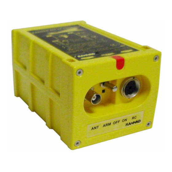
OPERATION MANUAL AF INTEGRA / AF-H INTEGRA ELT 4. ELT transmitter Connection Connect the cable of the outside antenna to the BNC connector of the front panel. Set the 3-position switch of the front panel to ARM. Figure 3: Installation, controls and connectors •... - Page 37 OPERATION MANUAL AF INTEGRA / AF-H INTEGRA ELT 6. Removal Switch the ELT to OFF. Disconnect the external antenna from the BNC connector of the ELT. If connected, disconnect the DIN 12 Connector of Remote Control Panel bundle from the DIN12 socket of the ELT.
- Page 38 OPERATION MANUAL AF INTEGRA / AF-H INTEGRA ELT PAGE INTENTIONALLY LEFT BLANK PAGE: 208 JUN 20/2013...
- Page 39 OPERATION MANUAL AF INTEGRA / AF-H INTEGRA ELT CHECK 1. Self-test A. Periodicity EUROCAE ED-62A Recommendations § 2.8.9 : "The battery source shall provide sufficient capacity for a self-test to be conducted according to the period specified by the manufacturer or at least once a month according to Cospas-Sarsat requirement."...
- Page 40 OPERATION MANUAL AF INTEGRA / AF-H INTEGRA ELT 3+1 LOW BATTERY VOLTAGE 3+2 LOW RF POWER 3+3 FAULTY VCO LOCKING (FAULTY FREQUENCY) 3+4 NO IDENTIFICATION PROGRAMMED 3+5 FAULTY VSWR (EXT. ANTENNA) 3+6 INTERNAL GPS SERIAL LINK If self-test fails, contact the distributor as soon as possible. Unless a waver is granted, flight should be cancelled (refer to National Aviation Authorities).
- Page 41 OPERATION MANUAL AF INTEGRA / AF-H INTEGRA ELT FF FE 2F 96 E3 AF 0F 0F 7F DF FF 62 60 B7 83 E0 F6 6C Example of same message decoded by Cospas-Sarsat Decoder: FF FE D0 96 E3 AF 0F 0F 7F DF FF 62 60 B7 83 E0 F6 6C...
- Page 42 OPERATION MANUAL AF INTEGRA / AF-H INTEGRA ELT PAGE INTENTIONALLY LEFT BLANK PAGE: 304 JUN 20/2013...
-
Page 43: General
OPERATION MANUAL AF INTEGRA / AF-H INTEGRA ELT TROUBLESHOOTING 1. General Procedure for fault isolation onboard uses the indicator light (red visual indicator) of the ELT’s front panel. This indicator light is activated by a self-test capability within the ELT. - Page 44 OPERATION MANUAL AF INTEGRA / AF-H INTEGRA ELT PAGE INTENTIONALLY LEFT BLANK PAGE: 402 JUN 20/2013...
-
Page 45: Schematics & Diagrams
OPERATION MANUAL AF INTEGRA / AF-H INTEGRA ELT SCHEMATICS & DIAGRAMS 1. Outline dimensions and weight with mounting bracket AF-COMPACT PAGE: 501 JUN 20/2013... -
Page 46: Outline Dimensions And Weight With Universal Mounting Bracket
OPERATION MANUAL AF INTEGRA / AF-H INTEGRA ELT 2. Outline dimensions and weight with universal mounting bracket PAGE: 502 JUN 20/2013... -
Page 47: Af Integra / Af Integra (Er), Axis Of Installation
OPERATION MANUAL AF INTEGRA / AF-H INTEGRA ELT 3. AF INTEGRA / AF INTEGRA (ER), axis of installation PAGE: 503 JUN 20/2013... -
Page 48: Af-H Integra / Af-H Integra (Er), Axis Of Installation
OPERATION MANUAL AF INTEGRA / AF-H INTEGRA ELT 4. AF-H INTEGRA / AF-H INTEGRA (ER), axis of installation PAGE: 504 JUN 20/2013... -
Page 49: Servicing
Note: (if required by the relevant Civil Aviation Authority). Some Civil Aviation Authorities may require the ELT be tested periodically. In this case, refer to Service Letter SL S1840501-25-05 "Guidelines for periodic inspection" available on the Service & Support section of Kannad Aviation Website. B. Battery replacement Testing of various elements and parameters of the ELT is mandatory when the battery is replaced. -
Page 50: Battery Replacement Requirements
[SAFT-FRIWO , Lithium Manganese Dioxide, 2 x M20 (D-type) cells] PLEASE CONTACT YOUR LOCAL DISTRIBUTOR Orolia S.A.S. refuse all responsibility and invalidate all warranty should other packs be installed. Battery available from any Kannad Aviation distributor or dealer. List of distributor available on our Web site: http://www.kannadaviation.com Orolia S.A.S. - Page 52 Distributed by Manufactured by Orolia S.A.S. Z.I. des Cinq Chemins CS10028 56520 GUIDEL - FRANCE Tél. / Phone : +33 (0) 2 97 02 49 49 Fax : +33 (0) 2 97 65 00 20 A Company of the Orolia Group DOC09078D Ref:0146257D...
Need help?
Do you have a question about the AF INTEGRA and is the answer not in the manual?
Questions and answers