Table of Contents
Advertisement
Quick Links
Advertisement
Table of Contents

Related Manuals for Kannad AF INTEGRA


Summary of Contents for Kannad AF INTEGRA
- Page 1 Ref. 0146259B Emergency Locator Transmitters A Company of the Orolia Group INITIAL INSTALLATION MANUAL AF INTEGRA / AF-H INTEGRA With built-in GPS and Integral Antenna TP PAGE : 1 Revision 01 Date of rev.: JUN 01/2011 First issue: OCT 10/2010...
- Page 2 Users are kindly requested to notify KANNAD of any discrepancy, omission or error found in this manual. Please report to our customer support: E-mail: support.sar@kannad.orolia.com Tel.: +33 (0)2 97 02 49 00...
-
Page 3: Table Of Contents
INITIAL INSTALLATION MANUAL AF INTEGRA / AF-H INTEGRA TABLE OF CONTENTS Introduction ................... 1 KANNAD INTEGRA System Presentation ..........1 System overview ....................1 Transmitter and bracket ..................2 Remote Control Panels (RCP) ................3 RC100 KIT ......................3 RC102 KIT ......................4 RC200 ......................... - Page 4 INITIAL INSTALLATION MANUAL AF INTEGRA / AF-H INTEGRA TABLE OF CONTENTS 121.5 MHz ......................31 Outline dimensions and weights ............33 Wiring diagrams .................. 48 Compatibility list for INTEGRA ELTs System ........53 Mounting brackets ....................53 Remote control panels (RCP) ................53 Outside buzzer ....................
-
Page 5: Introduction
AF INTEGRA / AF-H INTEGRA ELT system. 2. KANNAD INTEGRA System Presentation A. System overview NOTE: for details of approved part number of AF INTEGRA / AF-H INTEGRA system, Refer to Section 12. Compatibility list for INTEGRA ELTs System,... -
Page 6: Transmitter And Bracket
INITIAL INSTALLATION MANUAL AF INTEGRA / AF-H INTEGRA The most effective external antenna configuration is on top of the fuselage, aft of the wing or near the vertical stabilizer. The ELT and mounting bracket should be mounted in the aircraft as close as the antenna as practicable with a coaxial cable towards the antenna as short as possible. -
Page 7: Remote Control Panels (Rcp)
INITIAL INSTALLATION MANUAL AF INTEGRA / AF-H INTEGRA C. Remote Control Panels (RCP) Refer to Section 12. Compatibility list for INTEGRA ELTs System, page 53 Part Numbers of approved RCPs. The RCP must be installed in the cockpit to monitor and control the ELT status. -
Page 8: Rc102 Kit
INITIAL INSTALLATION MANUAL AF INTEGRA / AF-H INTEGRA (2) RC102 KIT The RC102 remote control panel is connected to the ELT via a 2-wire cable equipped with a DIN-12 connector or optional programming dongle on the ELT side and directly connected to the RCP on the other side. 2 types of front panels are supplied in the kit. -
Page 9: Rc300 / Rc300 Nvg
INITIAL INSTALLATION MANUAL AF INTEGRA / AF-H INTEGRA (4) RC300 / RC300 NVG The RC300 is connected to the ELT via a 4-wire bundle equipped with a DIN-12 connector or optional programming dongle on the ELT side and a D-SUB 9 PTS Male connector on the other side. -
Page 10: External Antennas
Connection to the ELT will be carried out with a 50 Ohm coaxial cable ended with two male BNC connectors. IMPORTANT NOTICE: KANNAD recommends a cable with radio electric properties similar or better to those of a RG58 cable. Note: the 50 Ohm coaxial cable and the male BNC connectors are not supplied. -
Page 11: Registration
INITIAL INSTALLATION MANUAL AF INTEGRA / AF-H INTEGRA 3. Registration A. General The ELT must be registered prior to installation onboard. When a 406 MHz ELT is installed in an aircraft, it is imperative that the aircraft owner register the ELT. Each 406 MHz ELT contains a unique identification code that is transmitted to the satellite. -
Page 12: Registration In Canada
INITIAL INSTALLATION MANUAL AF INTEGRA / AF-H INTEGRA of any changes to the status of your 406 MHz beacon could result in penalties and/or fines being issued under Federal Law. The owner or user of the beacon is required to notify NOAA of any changes to the registration information at any time. -
Page 13: Elt Installation
INITIAL INSTALLATION MANUAL AF INTEGRA / AF-H INTEGRA 4. ELT Installation A. ELT and bracket installation recommendations The ELT shall not be installed within 30cm (1 ft) of a compass or flux gate. The distance between ELT and antenna shall be determined so that, according to the coaxial cable choosen. -
Page 14: Elt Location Recommendations
ELT. For these reasons, KANNAD recommends to install the ELT in a location in such a way that the vertical extension of the integral antenna is exposed to a RF transparent window. - Page 15 Refer to Figure 10: KANNAD AF INTEGRA, axis of installation. AF INTEGRA may be installed on helicopter. The ELT unit should be mounted (with maximum tolerance of ± 2°): • with "Flight direction" arrow towards the front of the helicopter;...
-
Page 16: Fix The Mounting Bracket
INITIAL INSTALLATION MANUAL AF INTEGRA / AF-H INTEGRA Figure 11: KANNAD AF-H INTEGRA, axis of installation The "Direction of Flight " arrow shall point towards the front or the bottom of the helicopter (and not pointing 45° downwards): - If the AF-H INTEGRA is installed with the "Direction of Flight " arrow pointing towards the front of the helicopter, the ELT shall be mounted with the upper side pointing towards the top of the helicopter. -
Page 17: Elt Installation Procedure
Figure 12: Bracket installation D. ELT installation procedure Mount the transmitter on the bracket • For AF INTEGRA or AF INTEGRA (ER), with "Flight Direction Arrow" of the ELT pointed towards the front of the aircraft,according to Figure 10: KANNAD AF INTEGRA, axis of installation page •... - Page 18 INITIAL INSTALLATION MANUAL AF INTEGRA / AF-H INTEGRA Slide the self-stripping strap through the buckle. Ensure the buckle is correctly positioned (indifferently on right or left side of ELT) regarding the horizontal center line of ELT as shown Detail A.
-
Page 19: Antenna Installation
INITIAL INSTALLATION MANUAL AF INTEGRA / AF-H INTEGRA 5. Antenna Installation Use only whip, rod or blade approved antennas. A. Antenna Installation Recommendations (1)FAA Recommendations Installation must be made by qualified personnel in accordance with FAA regulations. Duplicating a previous installation may not be acceptable. -
Page 20: Antenna Installation Procedure
INITIAL INSTALLATION MANUAL AF INTEGRA / AF-H INTEGRA of antenna radiation patterns. Detuning of the 121.5 MHz antenna may be required avoid the effects of radiated inter-modulation products which may be possible from non-operating 121.5 MHz ELTs exposed to high levels of RF energy. - Page 21 INITIAL INSTALLATION MANUAL AF INTEGRA / AF-H INTEGRA See figure below: Figure 14: Antenna ground plane for non metallic aircraft According to the antenna to be installed, use the appropriate outline drawings and drilling masks to determine the hole patern and drill size refer to the...
-
Page 22: Rcp Installation
INITIAL INSTALLATION MANUAL AF INTEGRA / AF-H INTEGRA 6. RCP installation A. RCP Installation Recommendations The RCP shall be installed in the cockpit. The RCP shall be readily accessible from the pilot’s normal seated position. B. RCP Installation Procedure The RCP must be connected to the ELT via a DIN-12 connector (P/N S1820514-03) or a Programming Dongle (Refer to Section 12. -
Page 23: Rc100
INITIAL INSTALLATION MANUAL AF INTEGRA / AF-H INTEGRA (1)RC100 RC100 RCP is supplied as a kit (Refer to Figure 18: RC100 mounting diagram). Connection of RC100 requires a 3-wire bundle or 5-wire bundle if an outside buzzer is connected. A pin-to-pin wiring has to be provided by the installer with AWG24 wires. - Page 24 INITIAL INSTALLATION MANUAL AF INTEGRA / AF-H INTEGRA Figure 18: RC100 mounting diagram Connect RCP to ELT Solder the DIN12 connector or Programming Dongle on the other side of the bundle: Refer to Figure 40: RC100 Wiring diagram, page 48...
-
Page 25: Rc102
INITIAL INSTALLATION MANUAL AF INTEGRA / AF-H INTEGRA (2) RC102 RC102 RCP is supplied as a kit (Refer to Figure 19: RC102 mounting diagram, page 23). 2 types of front plates may be installed. Choose the appropriate front plate according to the aircraft’s instrument panel. The kit also includes 2 LEDs. - Page 26 INITIAL INSTALLATION MANUAL AF INTEGRA / AF-H INTEGRA • Insert LED (2c) fitted with LED stand (2d) inside the LED mounting (2); • Install the switch and PCB assembly (3b+3a) with washers (3c) and nuts (3d), locked position upwards. Tighten nut;...
- Page 27 INITIAL INSTALLATION MANUAL AF INTEGRA / AF-H INTEGRA Figure 19: RC102 mounting diagram PAGE: 23 JUN 01/2011...
-
Page 28: Rc200
INITIAL INSTALLATION MANUAL AF INTEGRA / AF-H INTEGRA Connect RCP to ELT Solder the DIN12 connector or Programming Dongle on the other side of the bundle (pins K and M): Refer to Figure 41: RC102 Wiring diagram, page 49 Stuck the "CAUTION label" on the cable bundle close to the DIN12 connector. - Page 29 INITIAL INSTALLATION MANUAL AF INTEGRA / AF-H INTEGRA Figure 20: Installation of RC200 with mounting tray Connection Refer to Figure 42: RC200 Wiring diagram, page 50 RC200 is an RCP without internal buzzer. It can be connected to an optional outside buzzer and/or to an external warning A 3-wire bundle is required to connect RC200 to the ELT.
-
Page 30: Rc300 / Rc300-Nvg
INITIAL INSTALLATION MANUAL AF INTEGRA / AF-H INTEGRA External warning installation and connection (option): Refer to Figure 42: RC200 Wiring diagram, page 50 Connect the female 9-pin D-SUB connector to the male 9-pin D-SUB plug of the RC200. (4) RC300 / RC300-NVG The RC300 RCP is designed to be installed in a standard rack of an aircraft cockpit. -
Page 31: Rc600 Nvg
INITIAL INSTALLATION MANUAL AF INTEGRA / AF-H INTEGRA (5) RC600 NVG The RC600 NVG RCP is designed to be installed in a standard rack of a military helicopter cockpit. As compliant with NF L 65-211 standard, no drilling is necessary to install this RCP.The precise location of RC600 is to be determined according to aircraft manufacturer instruction. -
Page 32: Outside Buzzer Installation
INITIAL INSTALLATION MANUAL AF INTEGRA / AF-H INTEGRA 7. Outside Buzzer Installation • Drill 3 x Ø 3mm holes according to drilling mask (Refer to Figure 28: Outside buzzer, Outline dimensions); • Fix the mounting tray (1) with 3 M3 screws and nuts or with 3 rivets;... -
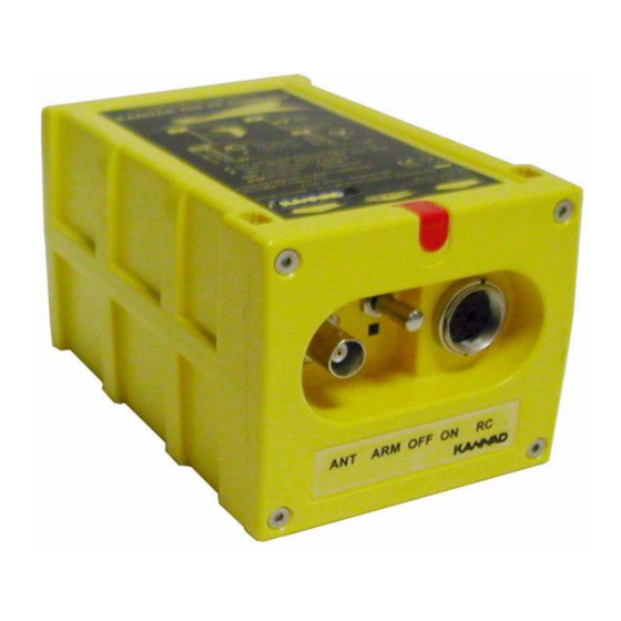
Page 33: Elt Connection
INITIAL INSTALLATION MANUAL AF INTEGRA / AF-H INTEGRA 8. ELT Connection Connect the cable of the external antenna to the BNC connector of the front panel. Connect the DIN12 connector of the Remote Control Panel cable to the DIN 12 socket of the front panel. -
Page 34: Rcp Operational Tests
INITIAL INSTALLATION MANUAL AF INTEGRA / AF-H INTEGRA Remark: The number of flashes gives an indication of the faulty parameter detected during the self-test. 3+1 LOW BATTERY VOLTAGE 3+2 LOW RF POWER 3+3 FAULTY VCO LOCKING (FAULTY FREQUENCY) 3+4 NO IDENTIFICATION PROGRAMMED 3+5 FAULTY VSWR (EXT. -
Page 35: 406 And 121.5 Mhz Transmission Test
INITIAL INSTALLATION MANUAL AF INTEGRA / AF-H INTEGRA C. 406 and 121.5 MHz transmission test NOTE: Transmissions tests only provide the aircraft operator with an indication that the ELT is transmitting; however, a positive result cannot be interpreted as meaning that the ELT meets all operational parameters. - Page 36 INITIAL INSTALLATION MANUAL AF INTEGRA / AF-H INTEGRA • Stop transmission: - either on ELT: OFF or ARM position; - or on the Remote Control Panel: press TEST and RESET (the ELT shall be in ARM position). - continue to listen to 121.5 MHz for a few seconds to ensure that the ELT does not continue to transmit after the test is terminated.
-
Page 37: Outline Dimensions And Weights
INITIAL INSTALLATION MANUAL AF INTEGRA / AF-H INTEGRA 10.Outline dimensions and weights Figure 24: Outline Dimensions and weight with Compact Mounting Bracket PAGE: 33 JUN 01/2011... - Page 38 INITIAL INSTALLATION MANUAL AF INTEGRA / AF-H INTEGRA Figure 25: Outline dimensions and weight with Universal Mouting Bracket PAGE: 34 JUN 01/2011...
- Page 39 INITIAL INSTALLATION MANUAL AF INTEGRA / AF-H INTEGRA Figure 26: Compact Mounting bracket (S1840502- 01), Outline dimensions and weight PAGE: 35 JUN 01/2011...
- Page 40 INITIAL INSTALLATION MANUAL AF INTEGRA / AF-H INTEGRA Figure 27: Compact Universal Mounting bracket (S1840502- 02), Outline dimensions and weight PAGE: 36 JUN 01/2011...
- Page 41 INITIAL INSTALLATION MANUAL AF INTEGRA / AF-H INTEGRA Figure 28: Outside buzzer, Outline dimensions Figure 29: RC100 Outline dimensions PAGE: 37 JUN 01/2011...
- Page 42 INITIAL INSTALLATION MANUAL AF INTEGRA / AF-H INTEGRA Figure 30: RC102 Outline dimensions PAGE: 38 JUN 01/2011...
- Page 43 INITIAL INSTALLATION MANUAL AF INTEGRA / AF-H INTEGRA Figure 31: RC200 Outline Dimensions PAGE: 39 JUN 01/2011...
- Page 44 INITIAL INSTALLATION MANUAL AF INTEGRA / AF-H INTEGRA Figure 32: RC300 Outline Dimensions PAGE: 40 JUN 01/2011...
- Page 45 INITIAL INSTALLATION MANUAL AF INTEGRA / AF-H INTEGRA Figure 33: RC600 Outline dimensions PAGE: 41 JUN 01/2011...
- Page 46 INITIAL INSTALLATION MANUAL AF INTEGRA / AF-H INTEGRA Figure 34: AV-200 Outline dimensions and weight PAGE: 42 JUN 01/2011...
- Page 47 INITIAL INSTALLATION MANUAL AF INTEGRA / AF-H INTEGRA Figure 35: ANT300 Outline dimensions and weight PAGE: 43 JUN 01/2011...
- Page 48 INITIAL INSTALLATION MANUAL AF INTEGRA / AF-H INTEGRA Figure 36: AV-300 Outline dimensions and weight PAGE: 44 JUN 01/2011...
- Page 49 INITIAL INSTALLATION MANUAL AF INTEGRA / AF-H INTEGRA Figure 37: ANT500, Outline dimensions and weight PAGE: 45 JUN 01/2011...
- Page 50 INITIAL INSTALLATION MANUAL AF INTEGRA / AF-H INTEGRA Figure 38: ANT560, Outline dimensions and weight PAGE: 46 JUN 01/2011...
- Page 51 INITIAL INSTALLATION MANUAL AF INTEGRA / AF-H INTEGRA Figure 39: ANT650, Outline dimensions and weight PAGE: 47 JUN 01/2011...
-
Page 52: Wiring Diagrams
INITIAL INSTALLATION MANUAL AF INTEGRA / AF-H INTEGRA 11.Wiring diagrams Figure 40: RC100 Wiring diagram PAGE: 48 JUN 01/2011... - Page 53 INITIAL INSTALLATION MANUAL AF INTEGRA / AF-H INTEGRA Figure 41: RC102 Wiring diagram PAGE: 49 JUN 01/2011...
- Page 54 INITIAL INSTALLATION MANUAL AF INTEGRA / AF-H INTEGRA Figure 42: RC200 Wiring diagram PAGE: 50 JUN 01/2011...
- Page 55 INITIAL INSTALLATION MANUAL AF INTEGRA / AF-H INTEGRA Figure 43: RC300 Wiring diagram PAGE: 51 JUN 01/2011...
- Page 56 INITIAL INSTALLATION MANUAL AF INTEGRA / AF-H INTEGRA Figure 44: RC600 Wiring diagram PAGE: 52 JUN 01/2011...
-
Page 57: Compatibility List For Integra Elts System
INITIAL INSTALLATION MANUAL AF INTEGRA / AF-H INTEGRA 12.Compatibility list for INTEGRA ELTs System A. Mounting brackets KANNAD Designation KANNAD Part Number COMPACT MOUNTING BRACKET KIT S1840502-01 COMPACT UNIVERSAL MOUNTING BRACKET S1840502-02 B. Remote control panels (RCP) KANNAD Designation KANNAD Part Number... -
Page 58: External Antennas
INITIAL INSTALLATION MANUAL AF INTEGRA / AF-H INTEGRA E. External antennas KANNAD Designation Manufacturer KANNAD Part Number ANT300 CHELTON 1327-82 0124220 WHIP ANT AV200 RAMI AV-200 0146150 ROD ANT AV300 RAMI AV-300 0146151 BLADE ANT500 SENSOR SYSTEMS 0124222 S65-8282-406 BLADE ANT560... - Page 60 Manufactured by Z.I. des Cinq Chemins BP23 56520 GUIDEL - FRANCE http://www.kannad.com Tél. / Phone : +33 (0) 2 97 02 49 49 Fax : +33 (0) 2 97 65 00 20 A Company of the Orolia Group DOC09081B Ref: 0146259B...
Need help?
Do you have a question about the AF INTEGRA and is the answer not in the manual?
Questions and answers