Table of Contents
Advertisement
Emergency Locator Transmitter
Orolia S.A.S. - A Company of the Orolia Group
P/N : S1820502-XX
P/N : S1820511-01
Revision 09
First issue: JUL /1999
INSTALLATION MANUAL
OPERATION MANUAL
KANNAD 406 AP
KANNAD 406 AP transmitter
Mounting bracket, 1 strap
DMA185K
Ref. 0139180K
TP PAGE : 1
Date of rev. JUL 24/2013
Advertisement
Table of Contents

Related Manuals for Kannad 406 AP


Summary of Contents for Kannad 406 AP
- Page 1 Orolia S.A.S. - A Company of the Orolia Group INSTALLATION MANUAL OPERATION MANUAL KANNAD 406 AP P/N : S1820502-XX KANNAD 406 AP transmitter P/N : S1820511-01 Mounting bracket, 1 strap TP PAGE : 1 Revision 09 Date of rev. JUL 24/2013...
- Page 2 Users are kindly requested to notify Orolia S.A.S of any discrepancy, omission or error found in this manual. Please report to our customer support: E-mail: support.sar@orolia.com Tel.: +33 (0)2 97 02 49 00...
- Page 3 INSTALLATION MANUAL OPERATION MANUAL KANNAD 406 AP RECORD OF REVISIONS REV. Nb REVISION DATE INSERTION DATE MAR 18/2004 MAR 18/2004 J.S. JAN 26/2005 JAN 26/2005 J.S. JUN 28/2005 JUN 28/2005 J.S. FEB 13/2008 FEB 13/2008 J.S. SEP 12/2008 SEP 12/2008 J.S.
-
Page 4: Record Of Revisions
INSTALLATION MANUAL OPERATION MANUAL KANNAD 406 AP RECORD OF REVISIONS PAGE INTENTIONALLY LEFT BLANK ROR PAGE: 2 JUL 24/2013... - Page 5 INSTALLATION MANUAL OPERATION MANUAL KANNAD 406 AP LIST OF EFFECTIVE PAGES SUBJECT PAGE DATE Title Page JUL 24/2013 Record of Revisions JUL 24/2013 JUL 24/2013 List of Effective Pages JUL 24/2013 JUL 24/2013 Table of Contents JUL 24/2013 JUL 24/2013...
- Page 6 INSTALLATION MANUAL OPERATION MANUAL KANNAD 406 AP LIST OF EFFECTIVE PAGES SUBJECT PAGE DATE JUL 24/2013 System Functional Description and Operation JUL 24/2013 JUL 24/2013 JUL 24/2013 JUL 24/2013 JUL 24/2013 JUL 24/2013 JUL 24/2013 JUL 24/2013 JUL 24/2013 JUL 24/2013...
- Page 7 INSTALLATION MANUAL OPERATION MANUAL KANNAD 406 AP LIST OF EFFECTIVE PAGES SUBJECT PAGE DATE JUL 24/2013 JUL 24/2013 JUL 24/2013 Troubleshooting JUL 24/2013 JUL 24/2013 Schematics and Diagrams JUL 24/2013 JUL 24/2013 JUL 24/2013 JUL 24/2013 JUL 24/2013 JUL 24/2013...
- Page 8 INSTALLATION MANUAL OPERATION MANUAL KANNAD 406 AP LIST OF EFFECTIVE PAGES PAGE INTENTIONALLY LEFT BLANK LEP PAGE: 4 JUL 24/2013...
-
Page 9: Table Of Contents
Description ......................1 World coverage with the COSPAS-SARSAT system ..........2 Environmental improvements of ELTs ..............2 G-Switch (shock detectors) ..................2 KANNAD 406 AP Presentation ............. 3 LINE REPLACEABLE UNITS ............... 4 Transmitter ......................4 Bracket ........................4 Remote Control Panel ................... 4 External antenna .................... - Page 10 INSTALLATION MANUAL OPERATION MANUAL KANNAD 406 AP TABLE OF CONTENTS Registration and Programming ............201 Pin programming option ..................201 ELT and bracket installation .............. 203 Installation recommendations ................203 FAA Recommendations .................. 203 TSO C126a Section 5 b. Application Data Requirements ......203 RTCA DO-182 Recommandations ..............
- Page 11 INSTALLATION MANUAL OPERATION MANUAL KANNAD 406 AP TABLE OF CONTENTS SCHEMATICS & DIAGRAMS ............501 Outline Dimensions ................501 Drilling Mask ..................502 Wiring ....................503 ANT AV200, outline dimensions and drilling mask ......504 ANT AV300, outline dimensions and drilling mask ......505 ANT300, outline dimensions and drilling mask .........
- Page 12 INSTALLATION MANUAL OPERATION MANUAL KANNAD 406 AP TABLE OF CONTENTS PAGE INTENTIONALLY LEFT BLANK TOC PAGE: 4 JUL 24/2013...
-
Page 13: Introduction
INSTALLATION MANUAL OPERATION MANUAL KANNAD 406 AP INTRODUCTION The instructions in this manual provide the information necessary for the installation and the operation of KANNAD 406 AP ELT. Servicing instructions (Refer to SERVICING page 601) are normally performed by shop personnel. - Page 14 INSTALLATION MANUAL OPERATION MANUAL KANNAD 406 AP PAGE INTENTIONALLY LEFT BLANK PAGE INTRO 2 JUL 24/2013...
-
Page 15: System Overview
INSTALLATION MANUAL OPERATION MANUAL KANNAD 406 AP SYSTEM OVERVIEW 1. COSPAS-SARSAT System A. Description Launched in the early eighties by the four founder countries (Canada, France, Russia, USA), the COSPAS-SARSAT system provides satellite aid to search and rescue (SAR) operations for maritime, aeronautical and terrestrial vehicles anywhere in the world. -
Page 16: World Coverage With The Cospas-Sarsat System
INSTALLATION MANUAL OPERATION MANUAL KANNAD 406 AP B. World coverage with the COSPAS-SARSAT system The major improvement is the use of the COSPAS-SARSAT system for processing aeronautical emergencies. The difference with the 121.5 / 243 MHz is that the 406 MHz transmission... -
Page 17: Kannad 406 Ap Presentation
AWG 24 . Power Supply . Nav System System without optional CS144 System with optional CS144 Figure 2: ELT system description The KANNAD 406 AP is designed to be installed on fixed wing aircraft or helicopters. PAGE: 3 JUL 24/2013... -
Page 18: Line Replaceable Units
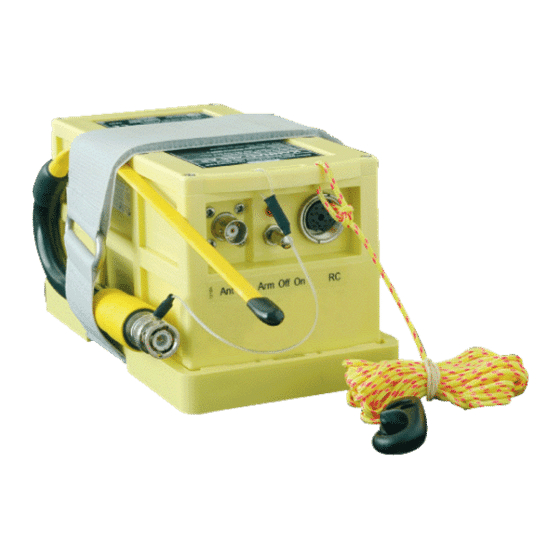
KANNAD 406 AP 3. LINE REPLACEABLE UNITS A. Transmitter The KANNAD 406 AP is an ELT designed to be installed on board aircraft to transmit a distress signal on 3 frequencies: • 406 MHz (COSPAS-SARSAT frequency) for precise pinpointing and identification of the aircraft in distress. -
Page 19: Design Features
KANNAD 406 AP 4. Design features A. General The KANNAD 406 AP belongs to the AP type of ELTs which are intended to be rigdly attached to the aircraft before the crash, but readily removable from the aircraft after a crash. -
Page 20: Compatibility List
INSTALLATION MANUAL OPERATION MANUAL KANNAD 406 AP 5. Compatibility list A. Remote control panels (RCP) Orolia Designation Orolia Part Number RC100 KIT S1820513-03 RC150 KIT S1820513-07 RC200 S1820513-11 RC200-NVG S1820513-14 RC300 S1820513-09 RC400 S1820513-05 RC500-320 S1820513-02 RC600 NVG (Y) S1820513-12... -
Page 21: External Antennas
INSTALLATION MANUAL OPERATION MANUAL KANNAD 406 AP D. External antennas Orolia Designation Manufacturer Orolia Part Number ANT560 DAYTON GRANGER 0145787 ELT 10-696-1 ANT410 DAYTON GRANGER 0145488 ELT 720063 ANT300 CHELTON 1327-82 0124220 ANT AV200 RAMI AV-200 0146150 ANT AV300 RAMI AV-300... - Page 22 INSTALLATION MANUAL OPERATION MANUAL KANNAD 406 AP PAGE INTENTIONALLY LEFT BLANK PAGE: 8 JUL 24/2013...
-
Page 23: System Functional Description And Operation
(thanks to a shock sensor) or manually (thanks to a switch on the transmitter itself or on a Remote Control Panel). The KANNAD 406 AP is designed to transmit on three frequencies (121.5, 243 and 406 MHz). The two basic emergency frequencies (121.5 and 243 MHz ) are mainly used for homing in the final stages of the rescue operations. -
Page 24: Controls
INSTALLATION MANUAL OPERATION MANUAL KANNAD 406 AP 2. Controls The following controls are to be found on the ELT front panel (from left to right): 3-position switch ARM/OFF/ON; Visual indicator (red); DIN 12 connector for connection to Remote Control Panel, CS144 interface module, dongle or programming equipment;... -
Page 25: Working Mode Information
INSTALLATION MANUAL OPERATION MANUAL KANNAD 406 AP 3. Working mode information The KANNAD 406 AP has 4 different modes: • Off. • Self-test (temporary mode). • Armed (standby mode to enable automatic activation by the shock sensor or by the remote control panel). - Page 26 INSTALLATION MANUAL OPERATION MANUAL KANNAD 406 AP C. Armed In order to enable activation by the G-Switch or with the Remote Control Panel, the ELT must be in standby mode with the switch in the "ARM" position. This mode is mandatory during flight. The ELT should remain in the "ARM"...
-
Page 27: Autonomy
INSTALLATION MANUAL OPERATION MANUAL KANNAD 406 AP 4. Autonomy The energy is provided by a battery pack composed of 3 LiMnO D cells (See pages 107 & 602 for Kit battery reference). Lithium cells, lithium batteries and equipment containing such batteries are subjected to regulations and classified under class 9 as from 1st of January 2003. -
Page 28: Electrical Characteristics
INSTALLATION MANUAL OPERATION MANUAL KANNAD 406 AP 5. Electrical characteristics Transmitter power supply: 3 x LiMnO D type cells. A. Electrical interface When installed on board, the ELT has to be connected: • to a Remote Control Panel via a DIN12 connector;... -
Page 29: Technical Specifications
INSTALLATION MANUAL OPERATION MANUAL KANNAD 406 AP IMPORTANT: The length of the coaxial cable should not exceed 2 meters (6 ft) for a standard RG58 or equivalent coaxial cable. If the cable length exceeds 2 meters, a low loss cable of attenuation less than 1 dB must be used. -
Page 30: Standby Mode For Automatic Activation
- During transmission, buzzer operates and visual indicator flashes. C. Manual activation as survival ELT The KANNAD 406 AP can be used external the aircraft in survival version. A tether is used to fix the transmitter to a liferaft in case of ditching. -
Page 31: Reset
INSTALLATION MANUAL OPERATION MANUAL KANNAD 406 AP Switch to "OFF". Disconnect the external antenna (ANT) and the Remote Control Panel (RC). Unfasten the Velcro® strap. Remove the transmitter and the auxiliary antenna from the bracket. Connect the auxiliary antenna (ANT). - Page 32 INSTALLATION MANUAL OPERATION MANUAL KANNAD 406 AP PAGE INTENTIONALLY LEFT BLANK PAGE: 110 JUL 24/2013...
-
Page 33: Installation / Removal
Any change of ownership shall also be declared and registered with the local registration authority and with the distributor. The KANNAD 406 AP is fully compatible with the four programming protocols defined by the COSPAS-SARSAT C/S G005 document: • Serialised Number. - Page 34 INSTALLATION MANUAL OPERATION MANUAL KANNAD 406 AP updates its own memory with the identification data contained in the Programming Dongle memory. When the ELT is removed from the aircraft, it keeps its identification data. For maintenance purposes, it is possible to delete the identification information of the ELT by connecting a "Maintenance Dongle"...
-
Page 35: Elt And Bracket Installation
INSTALLATION MANUAL OPERATION MANUAL KANNAD 406 AP 2. ELT and bracket installation A. Installation recommendations "The ELT shall not be installed within 60cm (2 ft) of a compass or flux gate. The distance between ELT and antenna shall be determined so that, according ≤... -
Page 36: Bracket Installation
INSTALLATION MANUAL OPERATION MANUAL KANNAD 406 AP aircraft structure as shown an FAA Advisory circular 43.13-2(), Chapter 2." B. Bracket installation • Determine the location of the ELT on board according to FAR/RTCA recommendations. CAUTION: Do not install the ELT in a location directly exposed to the sun. -
Page 37: Fixed Wings
"Direction of Flight" label pointed towards the front of the aircraft. (2) Helicopters The KANNAD 406 AP can be installed in its standard version on helicopter. The ELT unit should be mounted: • with the front face connectors pointing downwards at a 45° angle to the yaw axis (with maximum tolerance of 15°);... -
Page 38: Transmitter Installation
INSTALLATION MANUAL OPERATION MANUAL KANNAD 406 AP C. Transmitter installation • Verify that the ELT identification label matches the aircraft tail number. • Mount the transmitter on the bracket. • Slide the self-stripping strap thought the buckle and fasten it tightly. -
Page 39: Antenna Installation
INSTALLATION MANUAL OPERATION MANUAL KANNAD 406 AP Installation, controls and connectors) as shown Figure 2: ELT system description page Note regarding the external antenna: The specific installation (tightening torque, etc.) of the external antenna is not covered by this manual. Refer to antenna manufacturer's instructions. General... -
Page 40: Antenna Installation Recommendations
INSTALLATION MANUAL OPERATION MANUAL KANNAD 406 AP 3. Antenna Installation The external antenna can be either of whip, rod or blade type according to aircraft speed. Use only approved antennas. Connection to the ELT will be carried out with a 50 Ohm coaxial cable (RG58 for example) ended with two male BNC connectors. - Page 41 INSTALLATION MANUAL OPERATION MANUAL KANNAD 406 AP Locate a position on the fuselage according to § (2) RTCA DO-204a Requirements for ELT location. A double plate may be necessary for the antenna to meet rigidity specifications in Section (2) RTCA DO-204a Requirements for ELT location page 208.
-
Page 42: First Power Up
INSTALLATION MANUAL OPERATION MANUAL KANNAD 406 AP 4. First power up Perform the following tests: ELT operational tests: Refer to 2. ELT operational tests, page 302. RCP operational tests: Refer to 3. RCP operational tests, page 303. 406 & 121.5 MHz transmission tests (optional): Refer to 4. -
Page 43: Check
INSTALLATION MANUAL OPERATION MANUAL KANNAD 406 AP CHECK 1. Self-test A. Periodicity It is recommended by the manufacturer to test the ELT to detect any possible failure. It is recommended to perform a self-test once a month by pilot or maintenance personnel from the cockpit (Remote Control Panel) but it should not be done more than once a week. -
Page 44: Elt Operational Tests
INSTALLATION MANUAL OPERATION MANUAL KANNAD 406 AP 2. ELT operational tests A. Installation without programming dongle • connect RCP to J1 and outside antenna to J2; • switch the ELT from OFF to ARM; • check that the Self-Test result is OK (one long flash). -
Page 45: Rcp Operational Tests
INSTALLATION MANUAL OPERATION MANUAL KANNAD 406 AP 3. RCP operational tests Check correct operation of RCP LED and external buzzer by switching ELT and RCP as described in the sequential procedure hereunder (with ELT switch in the "ARM" position). Figure 301: RCP LED and buzzer operation IMPORTANT: (2) before switching the RCP to ON, wait for the end of the self-test. -
Page 46: And 121.5 Mhz Transmission Test
INSTALLATION MANUAL OPERATION MANUAL KANNAD 406 AP 4. 406 and 121.5 MHz transmission test A. ELT-Antenna link ELT -Antenna link can be checked by testing VSWR. Orolia S.A.S. recommends the use of SWR3000 VSWR meter manufactured by PROCOM or IFR 4000 Opt1 manufactured by AEROFLEX. -
Page 47: Troubleshooting
(4) 3+4 flashes - No identification programmed refer to relevant CMM for tests and repair. Note: for CMM download and other servicing instructions, refer to Service & Support section of Kannad Aviation Web site: : http://www.kannadaviation.com 3. Other faults detected A. Buzzer... - Page 48 INSTALLATION MANUAL OPERATION MANUAL KANNAD 406 AP PAGE INTENTIONALLY LEFT BLANK PAGE: 402 JUL 24/2013...
-
Page 49: Schematics & Diagrams
INSTALLATION MANUAL OPERATION MANUAL KANNAD 406 AP SCHEMATICS & DIAGRAMS 1. Outline Dimensions Note: all dimensions are in millimeters (inches in bracket) PAGE: 501 JUL 24/2013... -
Page 50: Drilling Mask
INSTALLATION MANUAL OPERATION MANUAL KANNAD 406 AP 2. Drilling Mask PAGE: 502 JUL 24/2013... -
Page 51: Wiring
INSTALLATION MANUAL OPERATION MANUAL KANNAD 406 AP 3. Wiring PAGE: 503 JUL 24/2013... -
Page 52: Ant Av200, Outline Dimensions And Drilling Mask
INSTALLATION MANUAL OPERATION MANUAL KANNAD 406 AP 4. ANT AV200, outline dimensions and drilling mask PAGE: 504 JUL 24/2013... -
Page 53: Ant Av300, Outline Dimensions And Drilling Mask
INSTALLATION MANUAL OPERATION MANUAL KANNAD 406 AP 5. ANT AV300, outline dimensions and drilling mask PAGE: 505 JUL 24/2013... -
Page 54: Ant300, Outline Dimensions And Drilling Mask
INSTALLATION MANUAL OPERATION MANUAL KANNAD 406 AP 6. ANT300, outline dimensions and drilling mask PAGE: 506 JUL 24/2013... -
Page 55: Ant410, Outline Dimensions And Drilling Mask
INSTALLATION MANUAL OPERATION MANUAL KANNAD 406 AP 7. ANT410, outline dimensions and drilling mask PAGE: 507 JUL 24/2013... -
Page 56: Ant560, Outline Dimensions And Drilling Mask
INSTALLATION MANUAL OPERATION MANUAL KANNAD 406 AP 8. ANT560, outline dimensions and drilling mask PAGE: 508 JUL 24/2013... -
Page 57: Servicing
Refer to CMM 25-63-01 or CMM 25-63-05. • Beacon Tightness CMM 25-63-01 or CMM 25-63-05. • "Testing and Fault Isolation" procedure as described in CMM 25-63-01. NOTE: • CMM 25-63-01: level 3 CMM, reserved for Kannad Aviation service stations only. PAGE: 601 JUL 24/2013... -
Page 58: Battery Replacement
INSTALLATION MANUAL OPERATION MANUAL KANNAD 406 AP • CMM 25-63-05: level 2 CMM, available upon request or on Kannad Aviation Website. C. Battery replacement Battery replacement is mandatory: • after more than 1 hour of real transmission (cumulated duration); • before or on the battery expiration date. - Page 60 Distributed by Manufactured by Orolia S.A.S Z.I. des Cinq Chemins CS10028 56520 GUIDEL - FRANCE Tél. / Phone : +33 (0) 2 97 02 49 49 Fax : +33 (0) 2 97 65 00 20 Web: http://www.kannadaviation.com A Company of the Orolia Group DMA185K Ref.: 0139180K...
Need help?
Do you have a question about the 406 AP and is the answer not in the manual?
Questions and answers