
Related Manuals for JDS Uniphase HP3-60-P4


Summary of Contents for JDS Uniphase HP3-60-P4
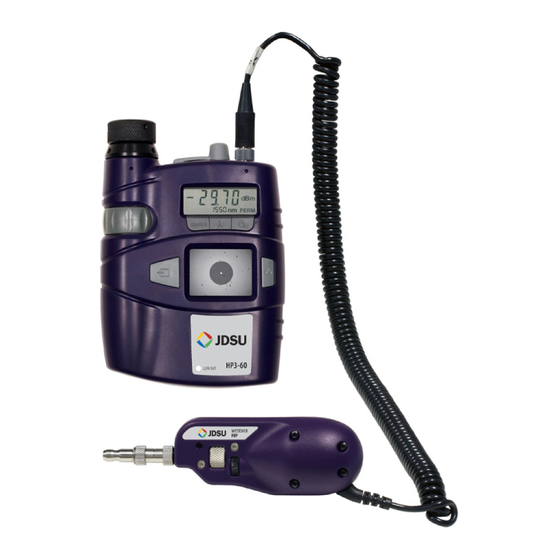
- Page 1 FBP ProBe MicroscoPe & HP3-60-P4 systeM Probe and system with integrated power meter and patch cord microscope User ManUal ZP-PKG-0502 REV 1...
- Page 2 Notice Every effort was made to ensure that the information in this document was accurate at the time of printing. However, information is subject to change without notice, and JDSU reserves the right to provide an addendum to this document with information not available at the time that this document was created.
-
Page 3: Table Of Contents
Contamination ........................... 9 Zones ..............................10 Zones Overlays ........................10 Acceptance Criteria ........................10 Single-mode .........................10 Multimode ..........................10 Chapter 3 FBP PROBE MICROSCOPE ......................11–12 Introduction ............................11 Controls ..............................12 Focus Control ........................12 Magnification Control ......................12 Specifications ...........................12 FBP PRoBE & HP3-60-P4 InsPEct and tEst systEm... - Page 4 FBPT Tip Installation Guide ......................15 FBPT Standard Inspection Tips Matrix ..................15 FBPT RibbonDrive Inspection Tips Matrix ................16 Chapter 5 HP3-60-P4 FIBER INSPECT & TEST SySTEM ............... 17–21 Introduction ............................17 HP3-60-P4 Features ........................18 Components and Functions .......................18 Improved Workflow and Benefits of PCM ................19 Inspection Time Trial Comparison (Traditional Display vs.
-
Page 5: Chapter 1 Jdsu Fiber Inspection Solutions
Simple Solution By implementing a SIMPLE yet IMPORTANT process of proactive visual inspection and cleaning, you can prevent poor signal performance and equipment damage. FBP PRoBE & HP3-60-P4 InsPEct and tEst systEm... -
Page 6: Good Fiber Connection
JdsU Fiber Inspection solutions cHaPter 1 good Fiber There are 3 basic principles that are critical to achieving an efficient fiber optic Connection connection: Perfect Core Alignment Physical Contact Pristine Connector Interface Light Transmitted CLEAN CONNECTION CLADDING CORE Today’s connector design and production techniques have eliminated most of the challenges to achieving core alignment and physical contact. -
Page 7: Chapter 2 Fiber Optic Connectors
The main components of a fiber connector are detailed below: Body Fiber Connector (Simplex) Fiber Ferrule Fiber Ferrule Alignment Sleeve Fiber Connection (Simplex) Physical Contact FBP PRoBE & HP3-60-P4 InsPEct and tEst systEm... -
Page 8: Body
Fiber optic connectors cHaPter 2 Body Houses the ferrule that secures the fiber in place; utilizes a latch and key mechanism that aligns the fiber and prevents the rotation of ferrules of two mated connectors. Ferrule Thin cylinder where the fiber is mounted and acts as the fiber alignment mechanism; the end of the fiber is located at the end of the ferrule. -
Page 9: Contamination
Scratches that touch the core are problematic because they create back reflection. CleAn ConneCtion DiRty ConneCtion BACK REFLECTION INSERTION LOSS Light Transmitted Light Transmitted DIRTY CONNECTION CORE CLADDING CLEAN CONNECTION CLADDING CORE CleAn FiBeR DiRt / ContAMinAtion PitS / ChiPS SCRAtCh FBP PRoBE & HP3-60-P4 InsPEct and tEst systEm... -
Page 10: Zones
Fiber optic connectors cHaPter 2 Zones Zones are a series of concentric circles that identify areas of interest on the connector end face. The inner-most zones are more sensitive to contamination than the outer zones. Zone Overlays A. Core B. Cladding C. -
Page 11: Chapter 3 Fbp Probe Microscope
This eliminates the need to disassemble hardware devices prior to inspection. FBP PRoBE & HP3-60-P4 InsPEct and tEst systEm... -
Page 12: Controls
FBP Probe microscope cHaPter 3 Controls The basic design of the Westover FBP probe microscope incorporates an imaging system, integrated light source, video camera, focus mechanism and magnification control. The probe is fully assembled and is powered by the display device. The only assembly required by the user is the connection to the display device and installation of the appropriate barrel assembly and/or the inspection tip. -
Page 13: Chapter 4 Fbpt Inspection Tips & Adapters
The barrel assembly houses the objective lens and works in conjunction with a number of tips. Note: Certain tips are equipped with integrated optics and do not require a barrel assembly (e.g., Long Reach Tips [FBPT-LC-L], Angled Tips [FBPT-SC-A6]). FBPP-BAP1 FBPP-BAP2 FBPP-BAP3 FBP PRoBE & HP3-60-P4 InsPEct and tEst systEm... -
Page 14: Standard Tips
FBPt Inspection tips & adapters cHaPter 4 Standard Tips (Bulkhead and Patch Cord) Standard bulkhead tips allow the user to inspect the fiber end face on the female side of FBPt-SC (Bulkhead) the bulkhead (e.g., inside hardware devices or on the back side of patch panels). Standard patch cord tips allow inspection of male ends of a fiber connection (e.g., patch cords, pigtails). -
Page 15: Fbpt Tip Installation Guide
Inspect 1.25 mm UPc patch cord FBPt-U12M connectors. Inspect lc/UPc connectors through a FBPt-lc-l bulkhead with 1/2-in longer reach. Inspect lc/aPc connectors through a lc/aPc FBPt-lc-aPc bulkhead. Inspect 1.25 mm aPc patch cord FBPt-U12Ma-sF connectors. FBP PRoBE & HP3-60-P4 InsPEct and tEst systEm... -
Page 16: Fbpt Ribbondrive Inspection Tips Matrix
FBPt Inspection tips & adapters cHaPter 4 FBPT STANDARD INSPecTIoN TIPS connector tyPe insPection tiP aPPlication DescriPtion Inspect st/UPc connectors through a FBPt-st bulkhead. Inspect st/UPc connectors through a FBPt-st-a6 bulkhead at a 60-degree angle. Inspect Fc/UPc connectors through a FBPt-Fc bulkhead. -
Page 17: Chapter 5 Hp3-60-P4 Fiber Inspect & Test System
Easy push-button operation makes the device simple and straightforward, while the inspect-test process procedure establishes proper, optimal workflow practices. FBP PRoBE & HP3-60-P4 InsPEct and tEst systEm... -
Page 18: Hp3-60-P4 Features
HP3-60-P4 Fiber Inspection and test system cHaPter 5 • HP3-60-P4 Fiber end face inspection and optical power testing with the same device • Features Integrated functions and features eliminate switching between multiple devices • Instantly inspect fiber when power level is low •... -
Page 19: Improved Workflow And Benefits Of Pcm
Inspect 1 port/channel at a time and prevent mis-routing ‚ Ensure patch cords stay clean by parking it in the patch cord microscope before ‚ connecting Inspection Time Trial (Average) Traditional Display Display with PCM FBP PRoBE & HP3-60-P4 InsPEct and tEst systEm... -
Page 20: Integrated Power Meter Features
HP3-60-P4 Fiber Inspection and test system cHaPter 5 • Integrated Easy-to-use, straightforward operation • Power Meter Features Reliable basic functionality for optical testing • Suitable for all single-mode and multimode applications, such as LAN, TELECOM, CATV, and DWDM testing •... -
Page 21: Power Meter Display Indicators
An error occurred in the program memory. This can cause malfunctions in keypad operation or cause the device to lock up. A checksum error occurred in the calibration data memory. The device calibration data are invalid. FBP PRoBE & HP3-60-P4 InsPEct and tEst systEm... -
Page 22: Hp3-60-P4 Display Specifications
HP3-60-P4 Fiber Inspection and test system cHaPter 5 HP3-60-P4 Display 148 x 81 x 42 mm ( 5.8 x 3.2 x 1.7 in) Dimensions Specifications 352 g (12.4 oz) with 6 x aa alkaline batteries Weight 1.8-in (45.7 mm) tFt Lcd... -
Page 23: Chapter 6 Fiber Inspection & Testing
These large particles are also known to break apart and migrate across the fiber surface when mated. OTDR Trace of Contamination and its Effect on Signal Performance FBP PRoBE & HP3-60-P4 InsPEct and tEst systEm... -
Page 24: Absolute Power
Fiber Inspection & Testing CHAPTER 6 Absolute Power The absolute power level (system power measurement) is the amount of optical power present in the system, measured in dBm. The source of this power is the transmitter or transceiver sending information through the system. This test determines whether the signal has enough power to operate the receiver or transceiver at the end of the link. -
Page 25: Relative Power
Note: "REF" will flash briefly on the power meter to indicate that the reference level is saved. Note: DO NOT disconnect the reference fiber from the light source (OLS). FBP PRoBE & HP3-60-P4 InsPEct and tEst systEm... -
Page 26: Attenuation Measurement
Fiber Inspection & testing cHaPter 6 Attenuation network System Measurement inspect inspect Probe Reference Reference Fiber 1 Fiber 2 inspect inspect Disconnect the power meter from reference fiber 1. Note: DO NOT disconnect reference fiber 1 from the light source (OLS). INSPECT, and if necessary, CLEAN all ends of the system port. -
Page 27: Appendix
JDSU's Westover FBP analog probe microscopes connect directly to Westover HD DISPLAyS (HD1, HD2, HD3, HP3-60) or to a PC/laptop or JDSU test platform (T-BERD/ MTS, FST) via a USB analog-to-digital converter. with HD-series displays USB analog-to-digital converter FBP PRoBE & HP3-60-P4 InsPEct and tEst systEm... - Page 28 Please con- tact JDSU for more information. JDSU and the JDSU logo are trademarks of JDS Uniphase Corporation. Other trademarks are the property of their respective holders. © 2009 JDS test and Measurement Regional Sales Uniphase Corporation.
Need help?
Do you have a question about the HP3-60-P4 and is the answer not in the manual?
Questions and answers