Table of Contents
Advertisement
Brushless motor / Brushless amplifier
• Thank you very much for your
purchase of Panasonic product.
• Please read this instruction
manual carefully for proper use.
• In particular, be sure to read
Safety precautions (P.2 to P.7)
before use for safety.
• Keep this manual with care after
reading, and read as necessary.
• This product is for industrial use
only and can not be used for
other uses eg home use.
Be sure to give this Instruction manual to an end user.
<Contents>
Safety precautions ......................................2
Introduction / Checking the model ..............8
Checking the model ....................................8
Name of part .............................................10
Installation ................................................12
Caution .....................................................15
System configuration and wiring...............16
Wiring .......................................................18
Test run .....................................................24
Checking load and use condition ................28
Assembling of gear head ..........................30
Maintenance/ inspections .........................31
Protective functions ..................................32
How to clear trip........................................34
Troubleshooting ........................................35
Technical Instructions
MINAS-BL GU series
• Label of safety precaution is affixed to the product.
page
How to use Digital key pad (option) ..........38
Operating instruction ...........................40
Test run (Digital key pad) ......................41
How to copy parameter ........................44
List of parameters (Default) ..................47
LED display ..........................................51
The function of parameters ...................52
Outline of PANATERM for BL ...................63
Example of operation pattern ...................63
Specifications ...........................................68
Options .....................................................74
List of peripheral equipments ...................78
Cautions for proper use ............................79
After-sale service (Repair) ......... Back cover
page
Advertisement
Table of Contents

Related Manuals for Panasonic MINAS-BL GU series


Summary of Contents for Panasonic MINAS-BL GU series
-
Page 1: Table Of Contents
Technical Instructions Brushless motor / Brushless amplifier MINAS-BL GU series • Thank you very much for your purchase of Panasonic product. • Please read this instruction manual carefully for proper use. • In particular, be sure to read Safety precautions (P.2 to P.7) before use for safety. -
Page 2: Safety Precautions
Safety precautions Important The following explanations are for things that must be observed in order to prevent Safety precaution in installation (continued) Danger harm to people and damage to property. ■ Misuses that could result in harm or damage are shown as follows, classified Install in an environment with pollution degree 2 or Preventing fire, electric according to the degree of potential harm or damage. - Page 3 Safety precautions Important Safety precaution in installation (continued) Safety precautions during operation Danger Caution Do not touch the brushless amplifier or brushless motor as Do not drop or topple products. Preventing damages. Cause of burn. it will be hot. Set up safety devices against idling and locking of the gear Preventing injury, Do not set very high velocity loop gain, and do not change Cause of injuries,...
- Page 4 Safety precautions Important Safety precautions during maintenance Other safety precautions Danger Danger Do not attempt to touch the keyway with bare hands The inspection work should be done after 15 minutes or Preventing electric shock. when it is provided on a shaft end of a motor or gear Cause of injuries.
-
Page 5: Introduction/ Checking The Model
Introduction/ Checking the model Checking the model After unpacking Checking the model of brushless motor • Make sure that the model is what you have ordered. Nameplate Example of the nameplate Motor type S1: Continuous rating • Check whether the product has been damaged or not during transportation. Model No. -
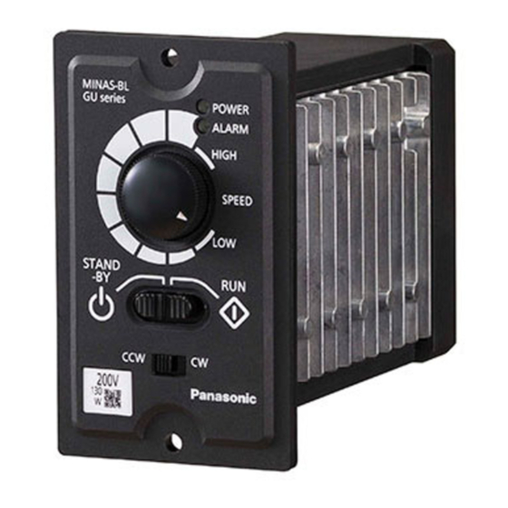
Page 6: Name Of Part
Name of part Name of part Brushless motor [Rear view] Connector for Do not loosen this screw. communications (SER) O-ring (not provided on a round shaft model) Grounding terminal ( Connector for motor Connector for motor cable and connection (MOTOR) 2 places Frame CS signal cable... -
Page 7: Installation
Installation Install the brushless motor and brushless amplifier properly for preventing failure Environmental condition and accident. Item Condition Transport Brushless motor –10 ℃ to 40 ℃ (free from freezing) Ambient Brushless amplifier 0 ℃ to 40 ℃ (free from freezing) •... -
Page 8: Caution
Installation Caution Cautions for Proper Use Installation of brushless amplifier • Install the product up and down correctly in the direction shown below. (1) Because the control circuit is sensitive to temperature and impact, read this instruction • Tightening torque of the product mounting screw should be selected appropriately so manual carefully for proper installation. -
Page 9: System Configuration And Wiring
(minimum guarantee current 1 mA or less) for preventing poor contact. <Example> Panasonic: DS type, HC type, OMRON: G2A type • Control Circuit Switch When using a switch instead of relay, use one for minute current in order to prevent poor contact. -
Page 10: Wiring
Wiring Wiring Function of terminal Standard wiring diagram Terminal for power supply (POWER) Part number of terminal block: 0138-7603 (DINKLE) • In case of 3-Phase 200 V Brushless amplifier Terminal Terminal Terminal explanation symbol name When extending the motor wires, use the optional Terminal for Connect the terminal to commercial power supply conforming to motor extension cable. - Page 11 Wiring *3 When the external variable resistor and the control ground (COM) are disconnected Connector for control signals (I/O) at the time of using the external variable resistor, 5 V is input to the FIN regardless of Connector on amplifier side: Parts No. S10B-PASK-2 (J.S.TMfg.,Co.,Ltd.) or equivalent. the setting of the variable resistor and the upper limit speed is commanded.
- Page 12 Wiring Connector for motor connection (MOTOR) Wiring example when using external speed setter as speed command and operating with external input When using the I 1 input, turn on the I 1 input enable switch (SW3) on the back of the Connector on amplifier side: Parts No.
-
Page 13: Test Run
Test run Inspection prior to test run/Test run Operation with external control signal Set the RUN switch on the front panel to “RUN”, the Inspection prior to test run rotate direction selector switch to “CCW”, and the I1 After completion of installation and wiring, check the connections and supplies as shown input enable switch (SW3) on the back of the prod- below: uct to “ON”. - Page 14 Test run With Console A <Connections on Consol A and I/O connector> I/O connector side Terminal Lead color of Console A side Speed potentiometer Power LED Terminal No. symbol a cable terminal No. I1 input Brown Direction enabled selector switch —...
-
Page 15: Checking Load And Use Condition
Checking load and use condition Check the use condition for extended use of the product. Particular use conditions may • Motor rotation speed: 3000 to 4000 r/min or less. Unit: N ・ m lead to heating or damage to the shaft. Fully check use conditions, and use the motor in a Model Reduction 10 12.5 15 18 20 25 30 36 50 60 75 90 100 120 150 180 200... -
Page 16: Assembling Of Gear Head
Assembling of gear head Maintenance/ Inspections Assembling of gear head Maintenance/ Inspections • Preparation for assembling Routine maintenance and inspection are essential for proper and satisfactory operation of the motor. (1) Use the product in combination with only the compatible gear head. Failure to observe this instruction will result in malfunction. -
Page 17: Protective Functions
Protective functions Protective functions Trip Protective Display on Description Measure number item Digital key pad Description of trip can be displayed only when the Digital key pad (option) or PC is con- It may have been caused nected. Protection function works even when the Digital key pad or PC is not connected, by excessive acceleration/ deceleration setting or gain but it is not displayed. -
Page 18: How To Clear Trip
How to clear trip Troubleshooting How to clear trip If any trouble should be found, follow the steps below for check and countermeasure. • If the cause cannot be found, it is recommended to use the Digital key pad, PANATERM If the brushless amplifier should trip, eliminate the cause and use any of the procedures (1) for BL, RS232 communication, and check the detail of trip. -
Page 19: Troubleshooting
Troubleshooting MEMO Phenomenon Detail of checking Measure, etc Check the position of the rotate direction selector switch (CW / CCW) on the front of the product. When using the input “ I 2”, Check the rotate direction setting. set the rotate direction selector switch to Motor rotates CCW. -
Page 20: How To Use Digital Key Pad (Option)
How to use Digital key pad (option) Name of each part and how to setup • Description Displays rotation speed (actual speed), setting speed, internal DC voltage, • What can be done by Digital key pad 5-digit LED load factor, and torque reference on 5-digit LED. This mode is set when •... -
Page 21: Operating Instruction
Operating Instruction Test run (Digital key pad) Inspection prior to test run/ Test run MODE • Press switch for changing display. LED表示 Turn on Monitor mode power. Inspection prior to test run Rotation speed 全 点 Internal speed (0-th (1) Make sure that all wiring is correct. 点滅... - Page 22 全 点 LED表示 Test run (Digital key pad) 点滅 灯 全 点 点滅 全 Digital key pad Digital key pad Description of 灯 Description of LED表示 LED表示 点 operation operation 灯 Switch LED display Switch LED display 全 全 • Internal speed Press 全...
-
Page 23: How To Copy Parameter
灯 How to copy parameter LED表示 全 点 灯 全 点 1. Reading a parameter value from brushless amplifier to the Digital key pad. 2. Copy a parameter value saved in the Digital key pad onto the brushless amplifier. 点滅 灯... -
Page 24: List Of Parameters (Default)
How to copy parameter List of parameters (Default) 3. Initializing of data of Digital key pad. Outline of parameters LED表示 • When any trouble occurs during copying, it can be often solved by initializing the Digital Brushless amplifier of this series is equipped with various parameters for adjustment and key pad. - Page 25 List of parameters (Default) Parameter setting Parameter setting Parameter Parameter Name of parameter Name of parameter Minimum Minimum Setting range Default Setting range Default Check Check unit unit of Digital key pad Trip Run command selection I 1/ I 2 Arriving O1 function selection Running...
-
Page 26: Led Display
List of parameters (Default) LED display LED display Parameter setting Parameter Name of parameter Minimum Setting range Default Check Figures displayed on the 7 segment display of the Daigital key pad are shown below: unit Denominator of Alphanumeric LED display Alphanumeric LED display display magnification 1 to 1000... -
Page 27: The Function Of Parameters
The function of parameters Parameter Parameter Name of parameter Description Name of parameter Description Desired running speed can be set. This is effective when You can select how to stop the motor. Internal speed “ 31 Speed command selection” is (PANEL). - Page 28 The function of parameters Parameter Parameter Name of parameter Description Name of parameter Description Run command can be chosen from the following: (2) 4th speed operation mode (PANEL): Setting to be chosen Command the motor to stop with switch of Digital key pad. OFF OFF Speed setting knob, internal speed (0-th speed) or FIN The motor cannot be operated by RUN switch on the front of...
- Page 29 The function of parameters Parameter Parameter Name of parameter Description Name of parameter Description (RUNSTOP. FORWARD-REVERSE) (2) When “ 30 Run command selection” is (PANEL), the State of I 1 motor can be commanded with switch of Digital key and I 2 Action pad.
- Page 30 The function of parameters Parameter Parameter Name of parameter Description Name of parameter Description (REVERSE-TRIP RESET) Set the upper limit of the motor setting speed. “ 31 Speed command selection ” For example, when is analogue CW run with switch I 1/ I 2 function voltage speed setting (VOL-A), motor setting speed at 5 V...
- Page 31 The function of parameters Parameter Parameter Name of parameter Description Name of parameter Description When “ 40 O1 function selection” and “ 41 O2 function selection” You can set the multiplying factor of a value displayed on 5-digit Numerator of display LED.
-
Page 32: Outline Of Panaterm For Bl
The function of parameters Outline of PANATERM for BL/ Example of an operation pattern Outline of PANATERM for BL Parameter Name of parameter Description Communicating software “PANATERM for BL” can do the following thing. Automatic reset in trip (trip retrial) can be set here. Trip can be is (1) Setting and saving of parameters of brushless amplifier and writing setting to memory automatically reset to allow operation to continue. -
Page 33: Conformance To Ec Directive And Ul Standard
Conformance to EC directive and UL standard EC Directives Configuration of peripheral equipment This brushless amplifier realizes compliance with the relevant standard of low voltage ・ 100 V system: Single phase 100 V to 120 V ± 10 %, 50 Hz/60 Hz directive in order to facilitate conformity to the EC directive of the machinery and equipment 200 V system: Single phase 200 V to 240 V ±... - Page 34 Conformance to EC directive and UL standard List of compatible peripheral equipment Surge absorber • DV0P4190 Optional parts Manufacturer's Part name Qty. Manufacturer [Unit: mm] number (option) parts number ø4.2±0.2 Circuit diagram Noise filter DV0P4170 SUP-EK5-ER-6 ① ② (single phase 100, 200 V) Noise filter DV0PM20042 3SUP-HU10-ER-6 1 (3-phase)
-
Page 35: Specifications
Specifications • Brushless motor specifications • Brushless amplifier GU series specifications Item Specifications Item Specifications Flange size 80 mm sq. 90 mm sq. Amplifier model No. MBEU5A1AAV MBEU5A5AAV MBEU9A1AAV MBEU9A5AAV MBEU1E1AAV MBEU1E5AAV Motor model No. MBMU5AZA○ MBMU9A1A○ MBMU9A2A○ MBMU1E1A○ MBMU1E2A○ Applicable motor MBMU5AZA〇... - Page 36 Speed control range 30 r/min to 4000 r/min (Speed ratio 1:133) Torque Allowable motor cable [N·m] Up to 10 m (Panasonic option cable) extension length 0.62 Protection level 115 %/ Overload protection time characteristics 150% 60 sec Instantaneous operation region 0.41...
- Page 37 Specifications • Gear head Dimensions [Unit: mm] MX8G□B • Motor Key and keyway (for 50W motor, option) [attachment] □ 50 W Round shaft type • A figure representing + 0.060 − 0.030 + 0.010 reduction ration in □ . Grounding terminal.
-
Page 38: Options
Housing : 39-01-2105(5557-10R-210) • Communication software PANATERM for BL Digital key pad side connector pin No. — — — Terminal : 39-00-0046(5556T2) Can be downloaded from our web site, free of charge. Please do not modify the cable. 39-00-0047(5556T2L) industrial.panasonic.com/ac/e/... - Page 39 Options • Control signal cable (Cable with an I/O connector) • Reactor [Unit: mm] Fig.1( for 3-phase power supply) Fig.2 (for single phase power supply) Optional parts number Length (L) L ±200 30±10 20±5 20±5 20±5 DV0PM20076 Heat shrinkable tube Cable AWG26 10-wire type Connector (J.S.T Mfg.
-
Page 40: List Of Peripheral Equipments
Options Cautions for Proper Use • O-ring Cautions for Proper Use Repair parts • Precautions for exporting this product and equipment incorporating this product. 10 pcs packed in one bag. Practical considerations for exporting the product or assembly containing the product. When the end user of the product or end use of the product is associated with military Size Part number... -
Page 41: After-Sale Service (Repair)
Pursuant to at the directive 2004/108/EC,article 9(2) Panasonic Testing Centre Panasonic Marketing Europe GmbH Winsbergring 15,22525 Hamburg,F.R.Germany For your records: The model number and serial number of this product can be found on either the back or the bottom of the unit.
Need help?
Do you have a question about the MINAS-BL GU series and is the answer not in the manual?
Questions and answers