Table of Contents
Advertisement
Quick Links
Advertisement
Table of Contents

Related Manuals for Hitachi KP-M20


Summary of Contents for Hitachi KP-M20
- Page 1 KP-M20/M30 B/W CCD Camera Operation Guide...
-
Page 2: Table Of Contents
Table of Contents General Composition Specifications Adjustment Timing chart External view External sync Connect cables Optical system 10. Optional 11. Notes to users Attachment Spectral sensitivity characteristic... -
Page 3: General
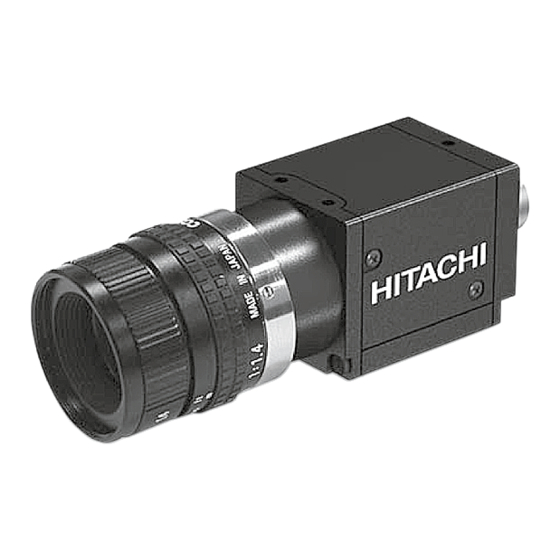
1. General The KP-M20/M30 are compact, lightweight, black and white cameras. The KP-M20 uses the atest high grade 1/2-inch image size CCD and the KP-M30 uses the high grade 1/3-inch image size CCD. The total pixel number of each CCD is 410,000(490,000 for CCIR). - Page 4 Specifications Internal synchronization scanning system 2:1 interlaced The horizontal number: 525 lines (CCIR: 625lines) fV=2fH/525 (CCIR: 625 lines) External synchronization I/O External switch selection. Set to Input at the factory. Input: HD/VD 4 6Vp-p Negative Frequency deviation: Impedance: 75 or high impedance. (Switch selection) Output: HD/VD 4 5Vp-p Negative Impedance: 100Ω...
- Page 5 4. NAME OF EACH SECTION “ ”...
- Page 6 4. NAME OF EACH SECTION...
-
Page 7: Timing Chart
5. Timing chart... - Page 8 5. Timing chart...
- Page 9 5. Timing chart...
- Page 10 5. Timing chart...
- Page 11 5. Timing chart...
- Page 12 5. Timing chart...
-
Page 13: External View
6. External View Mass approx. 55g Color BLACK... -
Page 14: External Sync
7. External synchronization (2:1 interlaced) When operating the camera by external drives signals, connect sync drive signals (HD, VD) to the DC /SYNC connector, then the mode is automatically switched from the interna l sync mode to the external sync mode. Horizontal and vertical drive signal inputs EIA: f(H) = 15.734 kHz CCIR: f(H) = 15.625 kHz... - Page 15 8. CONNECTION OF OPTIONS Signal connection to DC IN/SYNC connector. Signal connection to each pin...
-
Page 16: Optical System
9. Optical system 1)Flange focal Image size: 1/3-inch The flange focal distance is 17.526mm(in air). Flange focal distance cannot be adjusted. Note: Select such a lens as the length (A) from the flange su rface of the lens to the end of the screw side is 8mm or less. -
Page 17: Optional
10. Optional 1)Tripod adaptor TA-F30 (23885AX) 2)12-pin plug HR10A-10P-12S(01) Product code: 23810AX Viewed from this side 3)Junction box JU-F30 Product code: 23884AX... - Page 18 10. Optional 4)Dummy glass ARC1214 Parts code: XMD0009 5)Camera cables Mould type Assy type Shielded type C-201KSM C-201KS C-201KSS (23861AX) (23856AX) (23872AX) C-501KSM C-501KS C-501KSS (23862AX) (23857AX) (23873AX) C-102KSM C-102KS C-102KSS (23863AX) (23858AX) (23874AX) Specify assembly or shielded type at time of order. (): Product code Voltage drop due to a cable is about 0.01V per meter.
-
Page 19: Notes To Users
11. Notes to users Power supply nnect a 12V DC voltage (11 to 13V) from an external regulated DC power su pply. e a stable power supply without ripple and nois ior to turning on the power switch , check that the polarities of the p ower cable are correct , referring to the connection diagram To protect CCD (sensor) - Page 20 11. Notes to users Phenomena inherent to CCD imaging device Following are phenomena inherent to a CCD imaging device , and not defects. Smear and blo oming When strong light (lamp , fluorescent lamp , reflected light , etc.) is shot , pale bands are displayed vertically above and below the light.
- Page 21 Spectral sensitivity (typical example)
- Page 22 Hitachi Kokusai Electric is not liable for the losses caused when the equipment is used in a system used for business trades, production process, medical fields, crime prevention applications, etc.
Need help?
Do you have a question about the KP-M20 and is the answer not in the manual?
Questions and answers