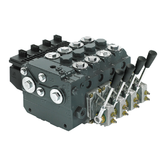
Danfoss PVG 100 Technical Information
Proportional valve group
Hide thumbs
Also See for PVG 100:
- Service and parts manual (44 pages) ,
- Service manual (44 pages) ,
- Installation manual (12 pages)
Table of Contents
Advertisement
Advertisement
Table of Contents

Related Manuals for Danfoss PVG 100


Summary of Contents for Danfoss PVG 100
- Page 1 Technical Information Proportional Valve Group PVG 100 www.danfoss.com...
- Page 2 March 2016 Updated for Engineering Tomorrow design. 0501 November 2015 Various updates 0500 January 2014 Converted to Danfoss layout – DITA CMS February 2006 - August 2013 Various changes BA - EA February 2005 New Edition 520L0720 | BC00000039en-US0502 ©...
-
Page 3: Table Of Contents
Remote control units ................................9 Function PVG 100 with open center PVPF...............................10 PVG 100 with closed center PVPV / PVPVP / PVPVM......................11 PVG 100 closed center priority steering PVPVP module ................... 12 PVG 100 closed center PVPVM module ........................... 12 PVG 100 basic modules PVB...............................12... - Page 4 PVG 100 Proportional Valve Group Contents PVG 100 with variable displacement pump schematic example................. 34 Electrically actuated PVG 100, variable displacement pump, PVB 100 with integrated pilot operated check valves..................................... 34 Electrically actuated PVG 100/32, fixed displ. pump, PVB 100/32 with integrated pilot operated check valves.....................................
- Page 5 PVG 100 dimensions in general..............................55 PVG 100 with open center PVPF dimensions........................56 PVG 100/32, closed center PVPV.............................. 57 PVG 100, Closed Center PVP with Integrated Priority Valve ..................58 Examples......................................59 Module selection chart Exploded view for module selection ............................. 64 PVG 100 order specification Please state.......................................69...
-
Page 6: General Information
Technical Information PVG 100 Proportional Valve Group General information Acronyms This table provides a definition of some commonly used terms PVG = Proportional Valve Group PVAS Assembly (Tie Rod) Kit Basic Module (Body) PVBE Basic End Module (Body) PVBO Basic Open Ended Module (Body) -
Page 7: General
From a simple load sensing directional valve to an advanced electrohydraulic controlled load independent proportional valve the PVG 100 modular system makes it possible to build up a valve group to fulfill customer requirements. The compact external dimensions of the valve remain unchanged whatever combination is specified. -
Page 8: Pvp - Pump Side Module
PVES – proportional, Super ‒ PVEH – proportional, high performance ‒ PVEH-F – proportional high performance, Float ‒ PVEA – proportional low hysteresis (not recommended for PVG 100-HF High Flow) ‒ PVEM – proportional, medium performance ‒ PVEO – ON/OFF ‒... -
Page 9: Remote Control Units
Technical Information PVG 100 Proportional Valve Group General information PVED-CC – Digital CAN controlled J1939/ISOBUS ‒ PVED-CX – Digital CAN controlled CAN open extra vehicle system safety ‒ PVEP – PVM controlled (11-32 V) ‒ ‒ PVHC – High Current actuator for PVG •... -
Page 10: Function
PVG 100 Proportional Valve Group Function PVG 100 with open center PVPF When the pump is started and the main spools in the individual basic modules are in the neutral position, oil flows from the pump, through connection P, across the pressure matching spool (11) to tank. The oil flow led across the pressure matching spool determines the pump pressure (stand-by pressure). -
Page 11: Pvg 100 With Closed Center Pvpv / Pvpvp / Pvpvm
6 – Pressure compensator 12 – Orifice PVG 100 with closed center PVPV / PVPVP / PVPVM In load sensing systems the load pressure is led to the pump control via the LS connection (2 in the diagram below). When the work functions are in the spring neutral position the LS pressure is drained to 520L0720 | BC00000039en-US0502 | 11 ©... -
Page 12: Pvg 100 Closed Center Priority Steering Pvpvp Module
Pilot operated check valve system PVBZ option (6, 8) on ports A and B are uses to reduce the work port to tank leakage eliminating the need for external actuator load holding in non-critical load holding applications. All PVG 100 modules contain an integrated T0 drain system to insure optimal performance 520L0720 | BC00000039en-US0502 12 | ©... -
Page 13: Pvg 100 Tank Modules
Technical Information PVG 100 Proportional Valve Group Function for PVBZ and all electrical actuation offerings. T0 is most effective when connected directly to the hydraulic system reservoir independent of the main Tank return system. PVG 100 tank modules Designed for low pressure drop at high return flows all PVT modules include facilities for PVLP shock valves insuring pressure passage spike protection during pump starvation recovery. -
Page 14: Load Sensing Controls
Technical Information PVG 100 Proportional Valve Group Function 3 – Priority spool for CF 10 – Shock and suction valve, PVLP 4 – LS connection for steering unit 11 – Main spool, PVBS 5 – Shuttle valve 12 – Max. oil flow adjustment screws for ports A and B 6 –Pilot operated check valve, POC... -
Page 15: Remote Pressure Compensated Controls
• Quick response to system flow and pressure requirements PVG 100 main spool with pressure compensated control The PC control maintains constant system pressure in the hydraulic circuit by varying the output flow of the pump. Used with a closed center control valve, the pump remains in high pressure standby mode at the PC setting with zero flow until the function is actuated. -
Page 16: Pressure Compensated System Characteristics
Technical Information PVG 100 Proportional Valve Group Function Typical operating curve Simple closed-center circuit Q max Pressur P101 166E P101 965 Once the closed center valve is opened, the PC control senses the immediate drop in system pressure and increases pump flow by increasing the swashplate angle. -
Page 17: Pvmr, Friction Detent
Technical Information PVG 100 Proportional Valve Group Function • Road rollers • Combine harvesters • Wood chippers PVMR, friction detent The friction detent PVMR allows the directional spool to be held in any position, resulting in infinitely variable, reversible, pressure compensated flow. -
Page 18: Pvbs, Main Spools For Flow Control (With Linear Characteristic)
Technical Information PVG 100 Proportional Valve Group Function bias spring pressure. Since the pressure drop varies with pump flow volume led to tank, the A and B work port flow will vary. In closed center systems, the pressure drop across the main spool equals the standby setting of the pump, measured at the P-port of the valve. -
Page 19: Safety
Technical Information PVG 100 Proportional Valve Group Safety Building in safety All makes and all types of control valves (including proportional valves) can fail. Thus the necessary protection against the serious consequences of function failure should always be built into the system. -
Page 20: Example Of A Control System For Manlift
Technical Information PVG 100 Proportional Valve Group Safety Example of a control system for manlift Example of a control system for man-lift Example of a control system for man-lift using PVE Fault monitoring input signals and signals from external sensors to ensure the PLUS+1 ®... -
Page 21: Examples Of Wiring Block Diagram
• PVSK, commonly used in crane application - full flow dump • PVPX, LS dump to tank PVG 100 – alternative LS dump/pilot supply disconnect: • PVPP, pilot oil supply shut off • External cartridge valve connecting LS pressure or main pressure to tank PVG 120 –... - Page 22 Technical Information PVG 100 Proportional Valve Group Safety A Emergency stop / man present switch B PVE Fault monitoring signals C Neutral signal detection D Deactivation of the hydraulic system (System Control Logic, example: PLUS+1® for signal monitoring and triggering signal)
-
Page 23: Example Of Fault Monitoring
Technical Information PVG 100 Proportional Valve Group Safety Example of fault monitoring Similar to previous example using fault monitoring for deactivation of the hydraulic system with extra fault inputs using the PVE’s with DI (Direction Indication) function. Example of fault monitoring for deactivation of the hydraulic system... -
Page 24: Pvg 32 - Mainly Used In System With Fixed Displacement Pumps
• PVSK, commonly used in crane application - full flow dump • PVPX, LS dump to tank PVG 100 – Alternative LS dump or pilot supply disconnect • PVPP, pilot oil supply shut off • External cartridge valve connecting LS Pressure to Tank •... -
Page 25: Technical Data
Intermittent operation: the permissible values may occur for max. 10% of every minute. PVG 100-HF - 350 bar [5075 psi] rated for 250 000 cycles, max. continuous pressure 320 bar [4640 psi]. PVG 100-HF - High Flow option work section. -
Page 26: Pvg 100 Pvm Operating Force
Proportional regulation range, control lever, standard spool ±19.5° Proportional regulation range ±15.3° Float position 22.3° Control lever positions No. 2 × 6 PVG 100 PVE reaction time and oil consumption PVE reaction time (s) Voltage Reaction time function PVEO PVEA PVEH PVES ON/OFF Prop. -
Page 27: Pveo Power Supply And Consumption
Technical Information PVG 100 Proportional Valve Group Technical data PVEO power supply and consumption Supply voltage U rated 12 V 24 V range 11 V to 15 V 22 V to 30 V max. ripple Current consumption at rated voltage 0.65 A @ 12 V... -
Page 28: Technical Characteristics
Technical Information PVG 100 Proportional Valve Group Technical characteristics The characteristics in this catalog are typical measured results. During measuring a mineral based hydraulic oil with a viscosity of 21 mm /s [102 SUS] at a temperature of 50°C [122°F] was used. -
Page 29: Pvg 100 Pressure Drop For Pvb, Basic Module
*With PVG100 High Flow body and spool Caution Because of flow forces, cylinder differential areas, Danfoss recommends LS margins under 25 bar [360 psi]. As noted above, work port flow is dependent upon the LS margin set on the pump. PC pumps maintain a constant discharge pressure which is equal to the PC setting on the pump. -
Page 30: Pvb With Pressure Compensation, Closed Center Pvp
Technical Information PVG 100 Proportional Valve Group Technical characteristics Pressure drop PVB for open spool in neutral position T neutral open center spool 100 130 3500 150/180 40/65 3000 2500 2000 1500 1000 l/min US gal/min V310204.A PVB with pressure compensation, closed center PVP... - Page 31 Technical Information PVG 100 Proportional Valve Group Technical characteristics Oil flow as a function of spool travel for spools A to F - 15 bar [218 psi] gal/min l/min l/min 0.04 0.08 0.12 0.16 0.20 0.24 0.28 0.50 0.55 0.60 0.65...
- Page 32 Technical Information PVG 100 Proportional Valve Group Technical characteristics PVLP/PVLA, suction valve The shock valve PVLP is designed to absorb shock effects. Consequently, it should not be used as a pressure relief valve. PVLP is set at an oil flow of 10 l/min [2.6 US gal/min].
-
Page 33: Pvhc Characteristic - Spool Stroke Vs Current
Technical Information PVG 100 Proportional Valve Group Technical characteristics PVHC characteristic - Spool stroke vs current Spool stroke, mm Ideal curve Hysteresis Current in mA @ 12V @ 24V 500/1000 mA 280/560 mA 280/560 mA 500/1000 mA V310 000.A PVHC current response and hysteresis @ 25 bar P , 21 ctS, 25 °C. -
Page 34: Hydraulic Systems
P301 790 gage 270 bar PC setting with 20 bar LS margin Electrically actuated PVG 100, variable displacement pump, PVB 100 with integrated pilot operated check valves P301 232 520L0720 | BC00000039en-US0502 34 | © Danfoss | May 2018... -
Page 35: Electrically Actuated Pvg 100/32, Fixed Displ. Pump, Pvb 100/32 With Integrated Pilot Operated Check Valves
Technical Information PVG 100 Proportional Valve Group Hydraulic systems Electrically actuated PVG 100/32, fixed displ. pump, PVB 100/32 with integrated pilot operated check valves 520L0720 | BC00000039en-US0502 | 35 © Danfoss | May 2018... -
Page 36: Other Operating Conditions
Non-flammable fluids Phosphate-esters (HFDR fluids) can be used without special precautions. However, dynamic seals must be replaced with FPM (Viton) seals. Please contact the Danfoss Sales Organization, if the PVG 100 valve is to be used with phosphate-esters. The following fluids should only be used according to agreement with the Sales Organization for Danfoss: •... - Page 37 Technical Information PVG 100 Proportional Valve Group Other operating conditions the return filter must be sized to suit the max. return oil flow. Pressure filters must be fitted to suit max. pump oil flow. Internal filters The filters built into PVG 32 are not intended to filter the system but to protect important components against large particles.
-
Page 38: Mounting
PV cover (PVH, PVMD, PVMR, PVMF or PVHC) would be on the “A” port side of the valve. The PVBS in PVG 100 are not symmetric. Because of this the “Load Sense” (Ls) holes in the PVBS main spool must be installed so that they are on the “B” port side of the PVB. -
Page 39: Modules And Code Numbers
Technical Information PVG 100 Proportional Valve Group Modules and code numbers PVPF (Open Center) Inlet Modules - for Pumps with Fixed Displacement Symbol Description BSP port SAE Port 1 5∕16-12 Open center pump side module for pumps with fixed 12 bar... -
Page 40: Pvp (Open And Closed) Accessories For Pump Side Modules
Technical Information PVG 100 Proportional Valve Group Modules and code numbers PVP (Open and Closed) Accessories for Pump Side Modules Symbol Description Code Number PVPP 12 V 11160318 Electrically Actuated Pilot Shut Off Valve 24 V 11160319 Normal Closed Solenoid Valve... -
Page 41: Pvpvp, Closed Center Priority Side Modules - For Pumps With Variable Displacement
Technical Information PVG 100 Proportional Valve Group Modules and code numbers PVPVP, Closed Center Priority Side Modules - for Pumps with Variable Displacement Symbol Description Code Number BSP port SAE port P: G¾ P: 1 1∕16-12 T: G1 T: 1 5∕16-12 CF: G½... -
Page 42: Pvb 100 Basic Modules - For Use With Standard Spools
Technical Information PVG 100 Proportional Valve Group Modules and code numbers PVB 100 Basic Modules - for use with standard spools Symbol Description Code Number BSP port SAE port G3/4 1 1∕16-12 UNF Without PVLP 161B6250 161B6650 Post Compensated With PVLP... -
Page 43: Pvb 100 Basic Modules - For Use With High Flow Spools
Technical Information PVG 100 Proportional Valve Group Modules and code numbers PVB 100 Basic Modules - for use with High Flow Spools Symbol Description Code Number BSP port SAE port A, B = G 3/4 1 3/16-12 UNF 11102180 11102181... -
Page 44: Pveo, On/Off Actuation
Code Number PVMR , Cover for friction detent 157B0015 PVMF , Mechanical float position lock, P -> A -> F 157B0005 Opposite of PVM, not compatible with PVG 100 PVBZ. PVEO, ON/OFF Actuation Symbol Description Hirschmann Deutsch ® 12 V... -
Page 45: Pvla, Anti-Cavitation Valve Fitted Into Pvb
Technical Information PVG 100 Proportional Valve Group Modules and code numbers Symbol Description Hirschmann Deutsch ® 11 - 32 V 11 - 32 V 11 - 32 V PVEH-DI Standard, active fault monitoring 157B4036 157B4096 Standard, passive fault monitoring 157B4037... -
Page 46: Pvlp, Shock / Anti-Cavitation Valve Fitted Into Pvb
Technical Information PVG 100 Proportional Valve Group Modules and code numbers PVLP, Shock / Anti-Cavitation Valve Fitted into PVB Symbol Description Setting Code number PVLP 157B2032 PVLP Shock and anti- 157B2050 cavitation valve 157B2063 (Not adjustable) 1160 157B2080 1450 157B2100... -
Page 47: Pvti 100/32, Interface Module
Without active elements 15∕8-UNF 161B2220 With T-port PVLP shock valve facility * Must use T0 equipped PVG32 Modules, for details see Danfoss Technical Information Basis Modules PVBZ, 520L0721. PVG 100 PVSI / PVT, Assembly Kit Description Code number 161B…. 1 PVB... -
Page 48: Pvg 32 Basic Modules With T0, Pvbz (Compatible With Pvg 100)
Technical Information PVG 100 Proportional Valve Group Modules and code numbers PVG 32 Basic Modules with T0, PVBZ (Compatible with PVG 100) Symbol Description PVBZ Without thermal With thermal relief relief valve 157B... valve 157B... Without compensator and load drop... -
Page 49: Pvg 32 Basic Modules With T0, Pvb (Compatible With Pvg 100)
Connection: A and B-port G 1/2 [ 7/8 in - 14] Please refer to Publications 520L0344 for PVBZ spool selection and to 520L0721 for the PVBZ modules with P.O. check. PVG 32 Basic Modules with T0, PVB (Compatible with PVG 100) Symbol Description PVB Code number 157B.. -
Page 50: Standard Spools For Electrical And Mechanical Actuation Progressive Flow Characteristics
Technical Information PVG 100 Proportional Valve Group Modules and code numbers Standard Spools for Electrical and Mechanical Actuation Progressive Flow Characteristics Symbol Pressure Compensated Flow (Specified flow is at 15 bar pump margin pressure) l/min [US gal/min] 40 [10.6] 65 [17.2] 100 [26.4]... -
Page 51: Spools For Friction Detent, Pvmr (Not Compatible With Pvbz 100) Progressive Flow Characteristics
Technical Information PVG 100 Proportional Valve Group Modules and code numbers Symbol Pressure compensated Flow (Specified flow is at 15 bar pump margin pressure) l/min [US gal/min] 40 [10.6] 65 [17.2] 100 [26.4] 130 [34.4] 150 [39.6] 180 [47.6] 4-way, 4-position, Closed Neutral Position, Hydraulic... -
Page 52: Standard Spools (Electrical And Mechanical Actuation) Throttled Open In Neutral, Linear Flow Characteristics
Technical Information PVG 100 Proportional Valve Group Modules and code numbers Standard Spools (Electrical and Mechanical Actuation) Throttled Open in Neutral, Linear Flow Characteristics Symbol Pressure Compensated Flow (Specified flow is at 15 bar pump margin pressure) l/min [US gal/min] 40 [10.6]... -
Page 53: High Flow Spools (Electrical And Mechanical Actuation) Progressive Flow Characteristics
Technical Information PVG 100 Proportional Valve Group Modules and code numbers High Flow Spools (Electrical and Mechanical Actuation) Progressive Flow Characteristics High Flow Spools (Electrical and Mechanical Actuation) Symbol Pressure Compensated Flow (Specified flow is at 15 bar pump margin pressure) -
Page 54: High Flow Spools, Full Open A/B → T And Neutral; Progressive Flow Characteristics
Technical Information PVG 100 Proportional Valve Group Modules and code numbers High Flow Spools, Full Open A/B → T and Neutral; Progressive Flow Characteristics High Flow Spools (Hydraulic and Mechanical Actuation) Symbol Pressure Compensated Flow (Specified flow is at 15 bar pump margin pressure) -
Page 55: Pvg 100 Dimensions In General
Technical Information PVG 100 Proportional Valve Group Dimensions PVG 100 dimensions in general P301 064 520L0720 | BC00000039en-US0502 | 55 © Danfoss | May 2018... -
Page 56: Pvg 100 With Open Center Pvpf Dimensions
Technical Information PVG 100 Proportional Valve Group Dimensions PVG 100 with open center PVPF dimensions Pp accumulator: G¼ [9∕16 in-18UNF] P: Pump port: G1 [15∕16 in-12UNF] T0 and LS: G¼ [9∕16 in-18UNF] L: LS relief valve P and Pp gauge: G¼ [9∕16 in-18UNF] G: PVPE unloading valve K: LX: G¼... -
Page 57: Pvg 100/32, Closed Center Pvpv
Technical Information PVG 100 Proportional Valve Group Dimensions 1 PVB 2 PVB 3 PVB 4 PVB 5 PVB 6 PVB 7 PVB 8 PVB L2 mm [in] [6.93] [8.82] [10.71] [12.60] [14.49] [16.38] [18.27] [20.16] PVG 100/32, closed center PVPV Pp accumulator: G¼... -
Page 58: Pvg 100, Closed Center Pvp With Integrated Priority Valve
[22.87] [24.76] It is recommended not to exceed 10 PVB 100/32 in a valve group. PVG 100, Closed Center PVP with Integrated Priority Valve CF: G½ [¾ in - 16 UNF] K: LX connection G¼ [9∕16 in - 18 UNF] LS: G¼... -
Page 59: Examples
[7.80] [9.69] [11.57] [13.46] [15.35] [17.24] [19.13] [21.02] Examples PVG 100 with variable displ. pump 3X Torque 38 - 42 N•m 131 ± 2.5 [5.16 ± 0.1] To port (9/16-18 SAE) 161 ± 3 12 ± 2 [6.34 ± 0.12] [0.47 ±... - Page 60 Technical Information PVG 100 Proportional Valve Group Dimensions PVPVM with two PVT modules 118.0 [4.65] 176.0 [6.93] 231.0 [9.09] 407.0 [16.02] 85.0 [3.35] P301 791 520L0720 | BC00000039en-US0502 60 | © Danfoss | May 2018...
- Page 61 Technical Information PVG 100 Proportional Valve Group Dimensions PVPVM with one PVT and one PVBE 118.0 [4.65] 81.0 [3.19] 185.0 [7.28] 240.0 [9.45] 416.0 [16.38] 40.0 [1.57] 85.0 [3.35] 474.0 [18.66] 520L0720 | BC00000039en-US0502 | 61 © Danfoss | May 2018...
- Page 62 Technical Information PVG 100 Proportional Valve Group Dimensions High Flow PVB module 46.2 [1.82] 1.8 [0.07] 17.0 [0.67] 181.0 [7.13] 198.0 [7.80] 100.5 [3.96] 86.5 [3.41] 52.0 [2.05] 5.3 [0.21] P301 793 PVBE mounting bracket R4.0 [R0.16] R10.2 [R0.40] 6.3 [0.25] 50.0 [1.97]...
- Page 63 Technical Information PVG 100 Proportional Valve Group Dimensions PVBSO module 59.8 [2.36] 218.9 [8.62] 14.8 [0.58] 26.2 [1.03] 9.7 [0.38] 16.0 [0.63] 86.0 [3.39] 10.0 [0.40] 45.0 [1.77] 9.9 [0.39] P301 795 520L0720 | BC00000039en-US0502 | 63 © Danfoss | May 2018...
-
Page 64: Module Selection Chart
Technical Information PVG 100 Proportional Valve Group Module selection chart Exploded view for module selection PVPP PVPD PVE, PVHC PVPE 1-12 PVPC PVBZ PVTI PVMD, PVH PVLP/A Assembly kit 157-699.11 PVP 100, Pump Side Module – Open center, PVPF with pilot supply (excludes PVPD/PVPE) - Page 65 Technical Information PVG 100 Proportional Valve Group Module selection chart PVP 100, Pump Side Module – Closed center, PVPV with pilot supply (continued) Port (includes pilot Closed center, PVPV with pilot supply gauge port) for PVE for PVE and facility...
- Page 66 Technical Information PVG 100 Proportional Valve Group Module selection chart PVPC, External pilot supply Code no. G¼ 7/16-20 UNF 1/2-20 UNF Weight Without check valve 157B5400 158X1000 0.05 kg [0.1 lb] With check valve 157B5600 157B5700 Not available for PVPV 157B5211 and 157B5611, (for details see catalog, 520L0344) PVM, mechanical actuation Code No.
- Page 67 Technical Information PVG 100 Proportional Valve Group Module selection chart Accessory Module for PVP 100 Code no. 12 V 24 V Weight PVPP, Pilot shut off valve 11160318 11160319 0.3 kg [0.7 lb] PVE, Electrical Actuation Code No. Hirsch DEUTSCH...
- Page 68 8 PVB Tie bolts and seals 161B8001 161B8002 161B8003 161B8004 161B8005 161B8006 161B8007 161B8008 Assembly Kit PVG 100 / PVTI Interface Module Description Code No. 0 PVB 1 PVB 2 PVB 3 PVB 4 PVB 5 PVB 6 PVB 7 PVB...
-
Page 69: Pvg 100 Order Specification
Inlet relief pressure setting 152 bar [2210 psi] An order form for Danfoss PVG 100 hydraulic valve is shown on the next page. The form can be obtained from the Danfoss Sales Organization. Both the module selection chart on the previous pages and the order form are divided into fields 0, 1-10, 11, 12, 13, a, b, and c. -
Page 70: Reordering
PVMD, PVE or PVH in field 'a'. Reordering The space at the top right-hand corner of the form is for Danfoss to fill in. The code number for the whole of the specified valve group (PVG No.) is entered here. -
Page 71: Specification Sheet
Technical Information PVG 100 Proportional Valve Group Specification sheet Specification form 520L0720 | BC00000039en-US0502 | 71 © Danfoss | May 2018... -
Page 72: Specification Example For Pvpvm
Technical Information PVG 100 Proportional Valve Group Specification sheet Specification example for PVPVM PVG Specification PVG PN PVG100 Subsidiary / Dealer: Application: Customer: 11144936 A - Port B- Port Function Mounting Bracket 11017006 PVAS PVBE 157B3171 11036948 11013084 157B4092 PVBE. SAE SPOOL 180L STANDARD ELECTRICAL ACTUATION PVEH.(G) Proportional. - Page 73 Technical Information PVG 100 Proportional Valve Group 520L0720 | BC00000039en-US0502 | 73 © Danfoss | May 2018...
- Page 74 Technical Information PVG 100 Proportional Valve Group 520L0720 | BC00000039en-US0502 74 | © Danfoss | May 2018...
- Page 75 Technical Information PVG 100 Proportional Valve Group 520L0720 | BC00000039en-US0502 | 75 © Danfoss | May 2018...
- Page 76 Phone: +86 21 3418 5200 Danfoss can accept no responsibility for possible errors in catalogues, brochures and other printed material. Danfoss reserves the right to alter its products without notice. This also applies to products already on order provided that such alterations can be made without changes being necessary in specifications already agreed.
Need help?
Do you have a question about the PVG 100 and is the answer not in the manual?
Questions and answers