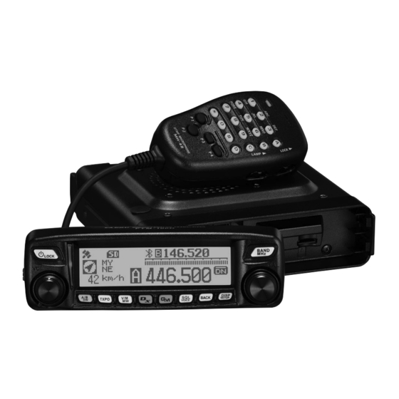
Yaesu FTM-100DR Operating Manual
144/430mhz dual band transceiver
c4fm/fm
Hide thumbs
Also See for FTM-100DR:
- Operating manual (177 pages) ,
- Instruction manual (82 pages) ,
- Update instruction manual (13 pages)
Table of Contents
Advertisement
Quick Links
FTM-100DR/DE
Operating Manual
144/430 MHz
DUAL BAND TRANSCEIVER
C4FM/FM
Before Use
Installation and Connection
Basic Operations
DG-ID and DP-ID Function
Using the Memory
Using the GPS Function
Using the APRS Function
Using the GM Function
Using the WIRES-X Function
Convenient Functions
Customizing Menu Settings and
User Preferences
Scanning
Appendix
Advertisement
Table of Contents

Related Manuals for Yaesu FTM-100DR


Summary of Contents for Yaesu FTM-100DR
- Page 1 FTM-100DR/DE Operating Manual 144/430 MHz DUAL BAND TRANSCEIVER C4FM/FM Before Use Installation and Connection Basic Operations DG-ID and DP-ID Function Using the Memory Scanning Using the GPS Function Using the APRS Function Using the GM Function Using the WIRES-X Function...
-
Page 2: Introduction
Voice guide unit FVS-2 (sold separately) provides voice announcements and recording of received audio *Refer to the separate “Advance Manual” * The Advance Manual, WIRES-X, APRS, and GM Instruction Manuals are not included with this product. Please download them directly from the Yaesu website. -
Page 3: About Registered Trademarks And Copyrights
Other company and product names listed in this manual are trademarks and registered trademarks of their respective companies. Unauthorized reproduction or copying of a part or all of the copyrights owned by Yaesu Musen Co., Ltd. in any form whatsoever is strictly prohibited. -
Page 4: Table Of Contents
Contents Introduction ..............2 Other settings ............34 Locking the DIAL and keys ........34 Features of this transceiver........2 About registered trademarks and copyrights ..3 Adjusting the date and time ......... 34 How to read this manual ........3 Restoring defaults (All Reset) ...... -
Page 5: Before Use
Before Use Safety Precautions (make sure to read these) Make sure to read this manual in order to use this radio safely and correctly. Before using this product, note that the company shall not be liable for any damages suffered by the customer or third parties, or for any failures and faults that occur during the use or misuse of this product, unless otherwise provided for under the law. - Page 6 Safety Precautions (make sure to read these) Do not operate the device when Do not touch any liquid leaking from flammable gas is generated. the liquid display with your bare Doing so may result in fire and hands. explosion. There is a risk of chemical burns occurring when the liquid comes Do not transmit in crowded places into contact with the skin or gets into...
- Page 7 Safety Precautions (make sure to read these) Do not use the device when the Refrain from using headphones and power cord and connection cables earphones at a loud volume. are damaged, and when the DC Continuous exposure to loud volumes power connector cannot be plugged may result in hearing impairment.
- Page 8 Safety Precautions (make sure to read these) Keep out of the reach of small Do not place the device on an children. unsteady or sloping surface, or in If not, this may result in injuries to a location where there is a lot of children.
-
Page 9: Checking The Supplied Items
Checking the supplied items Double-sided adhesive sheet DTMF microphone Bracket for main body Bracket for the MH-48A6JA MMB-36 controller Attachment screw set Controller cable DC power cable DC power cable (3 m) (with fuse attached) (with fuse attached) (USA, Asian version) (European version) Spare fuse (15 A) Spare fuse (15 A) -
Page 10: Name And Function Of Each Component
Name and function of each component Front panel Front ③ ④ ① ⑤ ⑥ ② ⑦ ⑧ ⑨ ⑩ ⑪ ⑫ ⑬ ⑭ ➀ Power/LOCK key ( Pressing the key for over 2 seconds switches the power between ON and OFF. Briefly pressing the key while the transceiver is turned ON engages or releases the key lock. - Page 11 TXPO key ( Briefly pressing each time switches the transmission power (HIGH/MID/LOW). Pressing and holding for over one second each time switches the signaling setting. For details, refer to the Advanced Manual (download from the Yaesu website). ➈ V/M MW key ( Briefly pressing each time switches between VFO mode and memory mode.
-
Page 12: Rear
Name and function of each component Rear ③ ① ① ② ➀ CONTROL jack Connect the control cable into this jack to connect to the main body. ➁ Screw hole to attach the mounting bracket ➂ Firmware update switch Caution Keep the rubber cap on when not in use. -
Page 13: Rear
Name and function of each component Rear ① ⑤ ② ③ ④ ➀ ANT terminal Connect the antenna. ➁ 13.8V DC Connect the provided DC power supply cable (with fuse attached). ➂ EXT SP jack Connect the optional external speaker. ➃... -
Page 14: Microphone (Mh-48A6Ja)
Changes the communication mode. [P4] Changes the transmit power. [PTT] Switches the transceiver to transmission mode. DTMF MICROPHONE MH-48 The desired functions can be assigned to buttons [P1] to [P4]. For details, refer to the Advanced Manual (download from the Yaesu website). -
Page 15: Screen Display
Name and function of each component Screen display ③ ① ④ ② ⑤ ⑥ ⑦ ➀ Icon display Displays the Bluetooth, APRS, micro-SD memory card and GPS icons when each function is in use. ➁ Station location information display Displays the received station’s location information and your station location information. -
Page 16: Input Characters
Name and function of each component ● GPS INFO screen While a received station’s information is displayed, [Location display] briefly press the key to display the GPS INFO screen. May also display the compass and the signal level of each acquired satellite. □ indicates an un-acquired satellite and ■... -
Page 17: Installation And Connection
Installation and Connection Installing the transceiver Precautions on installation Note the following when installing the transceiver. Do not install the transceiver in a place where it would be exposed to direct sunlight, high temperatures, excessive humidity, dusty conditions, or extreme vibrations. ... -
Page 18: Installation Location When Used In A Mobile Unit
Installing the transceiver Installation location when used in a mobile unit ● Front panel To efficiently receive the GPS satellites, it is recommended that the transceiver should be installed on the dashboard or front side of the center console. See “Installing the front panel”... -
Page 19: About The Antenna
Installing the transceiver About the antenna The antenna is an extremely important part for both transmitting and receiving. The antenna type and its inherent characteristics determine whether the performance of the transceiver can be fully realized. As such, please note the following: ... -
Page 20: Installing The Main Body
Installing the transceiver Installing the main body Install the main body using the supplied MMB-36 bracket. Select the installation location. Caution Select a location where the transceiver can be securely attached. See “Installation location when used in a mobile unit” on page 18. Drill four 6 mm diameter holes in the location where the bracket is to be mounted, matching the positions of the bolting holes of the bracket. -
Page 21: Installing The Front Panel
Installing the transceiver Installing the front panel Install the front panel using the supplied bracket. Caution The bracket can be formed by hand to match the location where the front panel is installed. Be careful not to cause an injury when bending the bracket. Select the installation location. -
Page 22: Connecting The Transceiver
Connecting the transceiver Connecting the front panel to the main body Caution Make sure to turn the transceiver OFF before connecting. Connect the supplied control cable to the transceiver main body. Main body Push the control cable plug into the CONTROL Control jack on the front panel of the transceiver main cable... -
Page 23: Connecting The Power Supply
Connecting the power supply Connecting the car battery When using the transceiver as a mobile unit, connect the DC power supply cable to the car battery. Cautions z Use the transceiver in a car with a negative ground system where the minus (−) pole of the battery is connected to the car body. -
Page 24: Basic Operations
Basic Operations Receiving Turning the power on Press and hold for over 2 seconds. The power switches on, and the display appears on the screen. <When using the same call sign for digital and APRS> <When using separate call signs for digital and APRS> The call sign for digital appears on the left and the call sign for APRS appears on the right. -
Page 25: Toggling The Operating Band
Receiving Press The display changes. The entered call sign appears at the bottom of the screen, and the screen switches to the frequency display screen. Toggling the operating band Normally, 2 operating bands appear on the top half and bottom half of the screen. The frequency and modulation mode may be changed only for the band on the top half of the screen, which is called “operating band”. -
Page 26: Adjusting The Squelch Level
Receiving Adjusting the squelch level Annoying noises can be eliminated when there is no signal present. The A-band and B-band squelch levels can be individually adjusted. Increasing the squelch level will be more effective in reducing noise; however setting the squelch level too high may block weak signals. -
Page 27: Tuning In To The Frequency
Receiving Tuning in to the frequency ● Using the DIAL Rotate the DIAL. Clockwise rotation tunes the frequency upwards, whereas counterclockwise rotation tunes the frequency downwards. ● Using the microphone Press [UP] and [DWN] briefly Pressing [UP] briefly, tunes the frequency upwards. Whereas pressing [DWN] briefly tunes the frequency in Number the downward direction. -
Page 28: Switching The Operation Mode
Receiving Rotate the DIAL to select [8 CONFIG], then press The menu list appears. Rotate the DIAL to select [7 FM AM STEP], then press Rotate the DIAL to select the desired frequency step. The frequency steps change in the following order: “AUTO”... -
Page 29: Selecting Communication Mode
The display switches to VFO mode and returns to the previous receive frequency. Selecting communication mode The FTM-100DR/DE transceiver is equipped with the AMS (Automatic Mode Select) function which automatically selects from 4 modes of transmission corresponding to the signal being received. -
Page 30: Switching The Modulation Mode
Receiving Switching the modulation mode In analog mode, the modulation mode can be selected from “AUTO”, “MANUAL (FM)” and “MANUAL (AM)”. When shipped from the factory, the mode is set to “AUTO” where the most optimal modulation mode is automatically selected according to the frequency. Select the desired operating band. -
Page 31: Communicating
Communicating Transmitting Press and hold [PTT] on the microphone. In analog mode, both the upper and lower portions of the mode/status indicator light red. In digital mode, the upper portion of the mode/status indicator lights red and the lower portion of the mode/ PQRS WXYZ status indicator lights blue. -
Page 32: Adjusting The Transmit Power
To use the half deviation, select “1 ON” from [2 TX/RX] → [7 HALF DEVIATION] in the Setup menu. Communicating using the repeater The FTM-100DR/DE includes the ARS (Automatic Repeater Shift) function which permits communication through repeaters automatically, by simply setting the receiver to the repeater frequency. -
Page 33: Tone Calling (1750 Hz)
Communicating Tone Calling (1750 Hz) If your transceiver is FTM-100DE (European version), press and hold in the program key [P1] of the microphone (MH-48) to generates a 1750 Hz burst tone to access the European repeater. The transmitter will automatically be activated, and a 1750 Hz audio tone will be superimposed on the carrier. -
Page 34: Other Settings
“UNLOCK” will be displayed on the screen. Adjusting the date and time The FTM-100DR/DE transceiver has a built-in clock. Set the time and date before using the radio. Also the clock is automatically set when signals are received from the GPS. - Page 35 Other settings Press The “Month” display blinks. Rotate the DIAL to select the month Press appears on the upper side). The “Day” display blinks. Press to go back ( appears on the upper side). Rotate the DIAL to select the day. Press appears on the upper side).
-
Page 36: Restoring Defaults (All Reset)
Performing the All Reset function clears all information registered to the memory channels. Be sure to write memory data down on paper or back up the data on a micro-SD memory card. For instructions on saving the data onto a backup micro-SD memory card, refer to the Advanced Manual (download from the Yaesu website). -
Page 37: Dg-Id And Dp-Id Function
DG-ID and DP-ID Function Digital Group ID (DG-ID) function The DG-ID function can set up two-digit DG-ID numbers from “00” to “99” separately for Transmit and Receive. By setting both transmit and receive to “00” (default), you can communicate with all the other stations in the digital C4FM mode. By matching the transmit DG-ID number to the uplink DG-ID number set in the club DR- 2X/XE System Fusion II digital repeater, you can access the digital repeater DR-2X/XE used in the club. - Page 38 Digital Group ID (DG-ID) function Tips • The transmit and receive DG-ID default number is set to “00”. • Normally, for general operation set the DG-ID number to “00” for both transmit and receive. Press the key to turn the GM (Group Monitor) function ON, then you can check whether or not other Group Member stations are operating within communications range.
-
Page 39: Digital Personal Id (Dp-Id) Function
Digital Personal ID (DP-ID) function Registering the DP-ID to a DR-2X digital repeater To register the transceiver DP-ID in the System Fusion II, DR-2X C4FM digital repeater, refer to the instruction manual of the DR-2X. By registering the transceiver’s DP-ID in the DR-2X, you can remotely control the settings and functions of DR-2X. -
Page 40: Deleting The Registered Dp-Id
Digital Personal ID (DP-ID) function 7 Press the key. When registering in the DP-ID list is finished, then the display returns to the DP-ID list screen. To continue operating without registering the DP-ID, Rotate the DIAL knob to select “Cancel” and then press the key. -
Page 41: Using The Memory
· “Programmable Memory Scan (PMS)” that scans only the specified frequency range (in the same frequency band)* * For details, refer to the Advanced Manual (download from the Yaesu website). The individual operating frequency and operating mode (modulation mode), as well as the other operating information, can be saved for each normal memory channel and PMS memory channel. -
Page 42: Recalling Memories
• Names can also be assigned to the memory channels. See “Naming a memory channel” on page 46. • 9 pairs of PMS memory channels can be written for the A-band and B-band each. For details, refer to the Advanced Manual (download from the Yaesu website). Recalling memories Press Switches to memory mode. -
Page 43: Recalling The Home Channel
Using the Memory Rotate the DIAL to select the desired memory channel. Press again to return to VFO mode. Unused memory channels are skipped. Recalling the home channel Press [P2] on the microphone. The home channel appears on the screen. Change the frequency by rotating the DIAL to return to VFO mode. -
Page 44: Changing The Frequency Of The Home Channel
Using the Memory Changing the frequency of the home channel The default frequency setting of the home channel can be changed. Switch to VFO mode. Rotate the DIAL to tune to the desired home channel frequency. Press and hold for over one second. The MEMORY WRITE screen appears. -
Page 45: Clearing Memories
Using the Memory Clearing memories Press and hold for over one second. The MEMORY WRITE screen appears. Press appears on the left side). Rotate the DIAL to select the memory channel from which memories are to be cleared. Press appears on the upper side). The erase confirmation screen appears. -
Page 46: Naming A Memory Channel
Using the Memory Naming a memory channel Names (memory tags) such as call signs and the names of the broadcasting stations can be assigned to the memory channels and the home channel. Up to 8 of the following characters can be entered as a memory tag. •... - Page 47 Using the Memory Rotate the DIAL to select [M], then press appears on the upper side). “M” is entered, and the cursor moves to the right. Tips • To move the cursor to the left, press appears on the upper side). •...
-
Page 48: Displaying The Memory Tag
LARGE SMALL Split memory A separate transmit frequency may be registered to a memory channel to which a receive frequency has already been registered. For details, refer to the Advanced Manual (download from the Yaesu website). -
Page 49: Receiving Weather Broadcast Channels (Usa Version Only)
Using the Memory Receiving Weather Broadcast Channels (USA version only) This radio includes the preprogrammed VHF Weather Broadcast Station Memory Channel Bank, and can receive the broadcast or the weather alert by recalling or scanning a desired channel. The following channels are stored in the weather station memory bank of this radio. Channel Frequency Channel... -
Page 50: Listening The Weather Alert
Using the Memory Listening the weather alert In the event of extreme weather disturbances, such as storms and hurricanes, the NOAA (National Oceanic and Atmospheric Administration) sends a weather alert accompanied by a 1050 Hz tone and subsequent weather report on one of the NOAA weather channels. -
Page 51: Scanning
Scanning Searching for signals The FTM-100DR/DE is equipped with a scanning function to search for memory channels and frequencies with active signals. Scanning can be performed using the following 5 methods: ● VFO scan Scan in VFO mode. ● All Memory Channel Scan Scan for all memory channels. -
Page 52: Selecting The Receiver Operation Performed After Scanning Stops
Searching for signals Selecting the receiver operation performed after scanning stops Select one of the following 3 receiving operations to be performed after the scanning stops. (1) Restart scanning after receiving the frequency for the set amount of time. Select from 1, 3 or 5 seconds. -
Page 53: Memory Scan
Searching for signals Memory scan Frequencies registered to the memory channels can be scanned in the memory channel number order. Switch to memory mode. Press and hold [UP] or [DWN] on the microphone for over one second. Pressing [UP] scans the memory channels in an upward direction. -
Page 54: Selecting The Scanning Method
Searching for signals Selecting the scanning method To scan all memory channels or only the specified memory channels. Press and hold for over one second. The Setup menu appears. Rotate the DIAL to select [3 MEMORY], and then press The menu list appears. Rotate the DIAL to select [2 MEMORY SCAN TYPE], then press The setting options appear. -
Page 55: Using The Gps Function
Using the GPS Function The FTM-100DR/DE transceiver is equipped with an internal GPS reception unit to receive and display the location information at all times. The location information can be used for the following purposes: Save the location information of other stations and note whether or not they are within communication range. -
Page 56: Using The Aprs Function
When using the APRS function, station information such as the call sign and symbol of your own station need to be set in the APRS initial setup menus. For details, refer to the APRS Instruction Manual (download from Yaesu website). -
Page 57: Using The Gm Function
The GM function enables the display of all stations operating the GM function (up to 24 stations). For detailed information about the operation and functions of the GM mode, refer to the separate GM Function Instruction Manual (download from Yaesu website). - Page 58 How to use the GM function ● Displaying all the stations that are transmitting in the GM function Tune to the designated frequency on the operating band. Press The GM function activates and displays up to 24 stations transmitting in the GM mode on the same frequency, or stations running in DN mode, within the communication range.
-
Page 59: Using The Wires-X Function
When the transceiver is connected to WIRES-X, the call sings of other stations and rooms on the WIRES-X are displayed. To establish a WIRES-X node station, the WIRES-X connection kit “HRI-200” sold separately is required. For details, refer to the separate WIRES-X Instruction Manual (download from the Yaesu website). -
Page 60: Convenient Functions
By matching the tone frequency with the partner station in advance, a quiet standby monitoring is possible. For details, refer to the Advanced Manual (download from the Yaesu website). Using the digital code squelch function This radio is equipped with a DCS (Digital Coded Squelch) function that allows audio to be heard only when signals containing the corresponding DCS code are received. -
Page 61: Setup Menu Basic Operations
Customizing Menu Settings and User Preferences From the Setup menu, the various functions of the transceiver may be customized according to your personal preferences. The functions are categorized into: display, transmission/reception, memory, device configuration, etc,. in the menu. It is easy to select the item to adjust from each menu list, and then input or select the desired setting. -
Page 62: Setup-Menu Listing
Setup-menu listing Selectable options Menu / Item Description (Options in bold are the default settings) 1 DISPLAY 1 SUB DISPLAY SELECT Sets the sub-display SUB BAND / TIME / VOLT content 2 LCD BRIGHTNESS Sets the screen MIN / 2 / 3 / 4 / 5 / 6 / MAX brightness 3 LCD CONTRAST Sets the screen contrast -3 / -2 / -1 / 0 / +1 / +2 / +3... - Page 63 Setup-menu listing Selectable options Menu / Item Description (Options in bold are the default settings) 9 SQL EXPANSION Sets the squelch ON / OFF type separately for transmission and reception 10 WX ALERT Weather alert operation ON / OFF (USA Version Only) setting 5 SCAN 1 DUAL WATCH STOP...
- Page 64 WP FORMAT: NMEA6 / NMEA7 / NMEA8 / NMEA9 WP FILTER: ALL / MOBILE / FREQUENCY / OBJECT/ITEM / DIGIPEATER / VoIP / WEATHER / YAESU / CALL RINGER / RNG RINGER 2 DATA SPEED Sets the APRS/DATA APRS: 1200 bps / 9600 bps...
- Page 65 Setup-menu listing Selectable options Menu / Item Description (Options in bold are the default settings) 10 APRS 1 APRS COMPASS NORTH UP / HEADING UP Sets the APRS compass display 2 APRS DISTINATION Displays the model code APY∗∗∗ (cannot edit) 3 APRS FILTER Mic-E: ON / OFF Sets the filter function...
- Page 66 Sets the sort and filter SORT: TIME / CALLSIGN / DISTANCE FILTER: ALL / MOBILE / functions FREQUENCY / OBJECT/ITEM / DIGIPEATER / VoIP / WEATHER / YAESU / OTHER PACKET / CALL RINGER / RANGE RINGER / 1200 bps / 9600 bps...
- Page 67 Setup-menu listing Selectable options Menu / Item Description (Options in bold are the default settings) 25 VOICE ALERT Sets the voice alert V ALERT: NORMAL / TONE SQL / DCS / function RX-TSQL / RX-DCS TONE SQL: 67.0Hz to 254.1Hz 100.0Hz DCS: 023 to 754 023 * For details of the functions, refer to the APRS Instruction Manual.
-
Page 68: Appendix
Appendix Optional components ① ⑦ ② ④ ③ ⑩ ⑨ ⑧ ⑤ ⑪ ⑫ ⑬ ⑥ ➀ PC connection cable (SCU-20) ➇ Microphone extension kit (MEK-2) *Same as the one provided ➈ Microphone (MH-42C6J) ➁ Cloning cable (CT-166) ➉ Multifunctional DTMF microphone (MH-48A6JA) ➂... -
Page 69: Specifications
Specifications ● General Frequency range : TX 144 - 146 MHz or 144 - 148 MHz 430 - 440 MHz or 430 - 450 MHz : RX 108 - 137 MHz (Air Band) 137 - 174 MHz (144 MHz HAM) 174 - 400 MHz (GEN1) 400 - 480 MHz (430 MHz HAM) 480 - 999.99 MHz (GEN2) Cellular Blocked (USA only) - Page 70 Specifications ● Receiver Circuit type : Double conversion super-heterodyne Intermediate frequencies : 1st : 47.25 MHz, 2nd :450 kHz Receiver Sensitivity 108 - 137 MHz (AM) 0.8μV typ for 10 dB SN 137 - 140 MHz (FM) 0.2μV for 12 dB SINAD 140 - 150MHz (FM) 0.2μV for 12 dB SINAD 150 - 174 MHz (FM)
- Page 71 SERVICE SIGNALS IS PROHIBITED UNDER FCC RULES AND FEDERAL LAW. EU Declaration of Conformity We, Yaesu Musen Co. Ltd of Tokyo, Japan, hereby declare that this radio equipment FTM-100DE is in full compliance with EU Radio Equipment Directive 2014/53/EU. The full text of the Declaration of Conformity for this product is available to view at http://www.yaesu.com/jp/red...
- Page 72 Copyright 2018 YAESU MUSEN CO., LTD. All rights reserved. No portion of this manual may be reproduced without the permission of YAESU MUSEN CO., LTD. YAESU MUSEN CO., LTD. Tennozu Parkside Building 2-5-8 Higashi-Shinagawa, Shinagawa-ku, Tokyo 140-0002 Japan YAESU USA 1806C-GC 6125 Phyllis Drive, Cypress, CA 90630, U.S.A.
Need help?
Do you have a question about the FTM-100DR and is the answer not in the manual?
Questions and answers