DoorKing 1837 Owner's Manual
90 series telephone entry and access control systems
Hide thumbs
Also See for 1837:
- Owner's manual (76 pages) ,
- Installation & owner's manual (76 pages) ,
- Product reference manual (42 pages)
Table of Contents
Advertisement
Installation/Owner's Manual
For 1837 circuit board:
1837-010 Revision Z or higher.
For 1835 circuit board:
1835-009 Revision Z or higher.
Date Installed:
Installer/Company Name:
Phone Number:
Leave Manual with Owner
Conforms To UL STD 294
Certified To CSA STD C22.2 # 205
Telephone Entry and Access Control Systems
1837
1837
1837
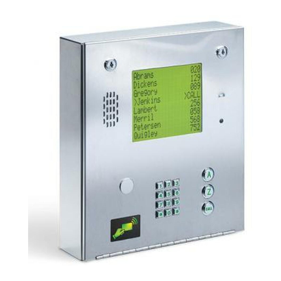
8 Line LCD Display
1835
1835
1835
Single Line LCD Display
Download REMOTE ACCOUNT MANAGER Software FREE at:
http://www.doorking.com/telephone/software
Copyright 2018 DoorKing
26, 30 and 31-Bit Wiegand Compatible
A d
a m
A k
s J
i n s
A n
M
n e s
> A
e J
n d
e r s
0 2
A p
o n
p l e
1 1
H
A u
g a
t e
s t i n
B
3 5
B a
D
> C
l s b
A L
a u
B a
g h
s s
B
6 5
J
0 7
2 2
3 2
1
2
4
3
5
7
6
8
9
0
A d
a m
s J
0 2
1
2
3
4
5
6
7
8
9
0
Model Number
Circuit Board
Serial Number
and Revision Letter:
®
, Inc. All rights reserved.
Copyright 2009 DoorKing, Inc. All rights reserved.
90 Series
90 Series
90 Series
1835-067-A-9-18
0
5
2
L
6
8
1
1
A
Z
C A
L L
0
A
Z
C A
L L
Advertisement
Chapters
Table of Contents

Subscribe to Our Youtube Channel
Related Manuals for DoorKing 1837


Summary of Contents for DoorKing 1837
- Page 1 Leave Manual with Owner Download REMOTE ACCOUNT MANAGER Software FREE at: http://www.doorking.com/telephone/software Copyright 2018 DoorKing ® , Inc. All rights reserved. Conforms To UL STD 294 Certified To CSA STD C22.2 # 205 Copyright 2009 DoorKing, Inc. All rights reserved.
- Page 2 QUICK GUIDE: Terminal Descriptions Relay 2 Note: Normally Open and Normally Closed relay jumper is used to set Relay 2 input on the See section 2.3 for terminal wiring. circuit board (See section 4.6). Main Terminal PHONE CGND SPKR 5VDC 16AC 16AC UL 294...
- Page 3 3.4.2 * 80 Factory message Programming the Instruction Message - 1835 ONLY 3.4.3 * 81 Factory message Programming the User Message - 1837 ONLY 3.4.4 * 80 Factory message Programming the Instruction Message - 1837 ONLY 3.4.5 * 81 Factory message Section 3.5 Programming Phone Numbers and Names...
- Page 4 Note: DoorKing cannot replace this specific lock or keys if lost. DoorKing, Inc. reserves the right to make changes in the products described in this manual without notice and without obligation of DoorKing, Inc. to notify any persons of any such revisions or changes. Additionally, DoorKing, Inc. makes no representations or warranties with respect to this manual. This manual is copyrighted, all rights reserved.
-
Page 5: Table Of Contents
3.2 Setup Telephone Entry System for PC Programming 3.2.1 Master Code 3.2.2 Number of Area Codes Allowed 3.2.3 Call-Up Operation when Interfacing with DoorKing 1816 or 1820 Systems 3.2.4 Resident Elevator Button Relay Time 3.2.5 “Tone Open” Sound ON or OFF 3.2.6 RS-232 Speed Setting 3.2.7... - Page 6 Test Connection to DKS Data over IP DKS Data over IP 6.1.9 Turn DKS Data over IP ON or OFF 6.2 Accessories 61-62 Wiring Schematics 1835 and 1837 SECTION 7 - LOG TABLES 7.1 Programming Information Tables 7.1.1 10 Area Codes 7.1.2 255 Area Codes 64-65 7.2 Resident Information...
- Page 7 Notice: DoorKing does not provide a power transformer on units sold outside of the United States. Use only transformers that are listed by a recognized testing laboratory to power the telephone entry system. An Inherently Protected Transformer must be used to power this device.
- Page 8 General Information • Prior to beginning the installation of the telephone entry system, we suggest that you become familiar with the instructions, illustrations, and wiring guidelines in this manual. This will help insure that you installation is performed in an efficient and professional manner. •...
-
Page 9: Section 1 - Installation
1.1 General Installation There are different ways to mount the 1835/1837 (On a wall, in a wall, attached to a architectural style post, kiosk, etc). They need a telephone line, power and communication wires run to them in conduit or inside a architectural style post. Feed all of the wires through the back or bottom of the entry system using the existing knock-outs provided in the enclosures. -
Page 10: Remove Components From Enclosure
1.2 Remove Components from Enclosure 1. Disconnect the two ribbon cables from the circuit board. C i r c u i o a r 2. Remove the two screws from the upper corners of the circuit board. c r e 3. -
Page 11: Enclosure Dimensions
1.3 Enclosure Dimensions Enclosure can be mounted directly to a wall, pilaster, post mounted using a OPTIONAL DoorKing architectural style mounting post or recessed in a wall (OPTIONAL Flush Mount Kit). The OPTIONAL Hood can be mounted to enclosure if desired. Be sure the unit is mounted securely and is not subject to vibration from closing doors or gates. -
Page 12: Install Enclosure
1.4 Install Enclosure Mount a Surface The illustrations below and next page show typical installations but specific installations can vary from this. See previous page for dimensions. t i n 1. Mount the enclosure using the mounting holes provided in the c r e corners (see next page for OPTIONAL flush mount kit OR hood ( N o... - Page 13 Mount OPTIONAL DKS Self-Standing Lighted Kiosk c k n The flush mount kit (Sold separately) is installed into the self-standing kiosk (P/N 1200-???) to secure entry system in place. Secure the rough-in box in the kiosk. Run all necessary wires to rough-in box.
-
Page 14: Memory Chip Replacement
1.5 Memory Chip Replacement The 1830 entry system is shipped with the memory chip already installed in the unit. However, if you need to replace the memory chip in the NEW 1830 entry system or replace the memory chips in an OLDER 1830, follow the instructions below. -
Page 15: Postal Lock Installation
Post Office uses for gang mailboxes. These locks are not available to the public. The installer or the building owner/manager will have to call the Post Office and arrange for the installation of this lock into the telephone entry system. All DoorKing commercial telephone entry systems are designed to accept installation of the postal lock. -
Page 16: Ul 294 Compliant Tamper Switch
1.7 UL 294 Compliant Tamper Switch The tamper switch needs to be connected to a security device or existing security system to comply with the UL 294 standard. Connect the 2 white wires of the Normally Closed gravity activated dry contact tamper switch to whatever security setup you desire. -
Page 17: Optional Internal Card Reader Installation
To Monitor, Video Recorder 500 ft. max. VTT-2000 UTP wire Video VTT-2000 To Monitor, DoorKing offers video adapters (Not supplied) for up to 1400 ft Adapter Video Video Recorder using unshielded twisted pair telephone wire. (P/N 1812-039) 1400 ft. max. Adapter... -
Page 18: Optional Heater Installation
1.10 OPTIONAL Heater Installation Install OPTIONAL heater as shown (P/N 2600-584). For cold weather climates where temperatures routinely drop below 40°F (4°C). The thermostat will automatically control the temperature inside operator housing. L IT S IN L IN D IS D IS IN E Attach the thermostat on the bottom inside of the... -
Page 19: Section 2 - Wiring
By A Switch. “Optional” 12 volt .8 amp hour gel-cell batteries (DoorKing P/N 1801-008) can be installed to provide stand-by power in the event of a power outage. Two batteries are required, one for the system power and one for the auxiliary terminal power. -
Page 20: Grounding
The use of surge suppressors can significantly reduce the chance of component failure because of static charges or surges. DoorKing recommends Installing a Phone Line surge suppressor (DoorKing P/N 1877-010 or equivalent) and a Low Voltage surge suppressor (DoorKing P/N 1878-010 or equivalent) to help protect the entry system from power surges. -
Page 21: Terminal Descriptions
2.2 Terminal Descriptions Relay 2 Note: Normally Open and Normally Closed relay jumper is used to set Relay 2 input on the See section 4 on page 51 for the locations of the terminals on the circuit board. circuit board (See section 4.6). Main Terminal PHONE CGND... -
Page 22: Backlite Cutoff
Power Input for 1837 Phone System 40 VA “CGND” Ground 40 VA power for the 1837 phone system ONLY. DO NOT use a 20 VA transformer for the 1837. See section 2.1.3. Red (Pos) “PSW” & “COM” “BAT” & “COM” - 12 VDC Back-Up Battery Input (Phone System) - Page 23 2.3.2 Tracker Expansion Boards (Hardwired) The model 2358 Tracker Expansion Board (sold separately) allows you to expand the number of remote entry points that the telephone entry system can control. One tracker expansion board is required for EACH remote entry point. Up to 48 boards can be hardwired to the circuit board’s Aux Terminal (First 24 boards connected to #7 - #9 and 24 more boards connected to #11 - #13 if needed).
-
Page 24: Tracker Expansion Boards Using Wireless Communication
(See Tracker Expansion Board Manual 2358-065 for ALL programming options). See DoorKing’s web site and the instruction sheets with the wireless kits for complete installation information when using wireless communication. -
Page 25: Doorking Cellular Network Connection - Voice/Data Transfer
DKS Software setting: Modem to Modem Use Telephone line for Voice Connection. 2.4.1 DoorKing Cellular Network Connection - Voice/Data Transfer Requires VOICE/DATA Cellular System kit (P/N 1800-080). Manage 2 (two) entry systems through DoorKing’s cellular network server where cellular service is available. VOICE/DATA... -
Page 26: Dks Data
Your PC connected to the internet, wired or wireless. 2.4.2b DoorKing VoIP Internet Connection - Voice/Data Transfer Requires a DKS TCP/IP Converter Kit P/N 1830-186 and VoIP Adapter Kit P/N 1815-568. Works with DoorKing’s Data over IP through the internet. 325 ft Max. -
Page 27: D Doorking Tcp/Ip Converter Mounting Position
2.4.3a DoorKing IM Server Modem Connection - Voice/Data Transfer NO additional hardware required. Works with DoorKing’s IM Server modem over the internet. DoorKing Voice and data transfer service is available for one low monthly fee without any long term contracts. -
Page 28: Direct Connection To Pc Options - Data Transfer Only
2.5 Direct Connection to PC Options - Data Transfer ONLY 2.5.1 RS-232 Direct Connection to PC - Data Transfer ONLY RS-232 Terminal Description Requires DoorKing RS-232 9-pin cable P/N 1818-040 and RS-232 to USB Adapter P/N 1815-037 to connect to a PC. RS-232... -
Page 29: Section 3 - Programming
DKS servers. If any of these advanced features are used, the system MUST be programmed with a PC using the DoorKing Remote Account Manager for Windows software, VERSION 6.4.i or higher. Refer to the software help screen for more information on these advanced features. -
Page 30: System Memory Chip Identification
Chip Locations 3.2 Set-up Telephone Entry System for PC Programming Prior to using a PC to program this PC Programmable Telephone Entry System with the DoorKing Remote Account Manager for Windows software, the programming steps in section 3.2.1 through 3.2.12 factory settings MUST be reviewed or re-programmed if necessary (most factory settings are typically desired). -
Page 31: Number Of Area Codes Allowed
3.2.3 Call-up Operation when Interfacing with DoorKing 1816 or 1820 Systems This feature is ONLY used when the telephone entry system is interfaced with a DoorKing 1816 or 1820 Telephone Intercom system under certain special applications. This CALL-UP feature provides special programming that will allow the system to call the phone number of a CO (Central Office) line connected to these systems. -
Page 32: Rs-232 Speed Setting
3.2.6 RS-232 Speed Setting The following programming sequence sets an optional slower RS-232 speed. This feature is available on Rev M boards or higher and the Remote Account Manager Software, Version 6.4.i, must be used. Factory setting = 1 (19200 baud rate) 1. -
Page 33: Dks Data Over Ip Phone Number Or System Id Number
The following programming sequence is necessary ONLY when using DoorKing DKS Data over IP. After installing the Remote Account Manager Software, Version 6.4.i, there is an option to use the DoorKing DKS Data over IP service type on the System Information screen. - Page 34 Remote Account Manager Software. If any of these advanced features are being used, DO NOT proceed with any other programming steps in this manual. PC’s only, NOT for use with MACs Download REMOTE ACCOUNT MANAGER Software FREE at: http://www.doorking.com/telephone/software 1835-067-A-9-18...
- Page 35 3.4.2 * 80 Factory message Programming the Instruction Message - 1835 ONLY 3.4.3 * 81 Factory message Programming the User Message - 1837 ONLY 3.4.4 * 80 Factory message Programming the Instruction Message - 1837 ONLY 3.4.5 * 81 Factory message Section 3.5 Programming Phone Numbers and Names...
-
Page 36: General Programming Using The System Keypad
3.3 General Programming Using the System Keypad Proceed with the programming steps on the following pages ONLY IF PC programming WILL NOT be used. The system keypad may be used to program some features on the telephone entry system but can be a little tedious to use. -
Page 37: Tone Open Numbers 33 3.3.3
3.3.3 Tone Open Numbers These steps will program the tone open numbers for Relays 0, 1 and 2. You will need to enter a four-digit number (see chart below) to set the relay functions. If a function is not desired, enter # in place of a number. If Expansion boards are connected to the system, there is no need to set a momentary open tone open number for the Expansion control relay(s). -
Page 38: Touch-Tone / Rotary-Dial 34 3.3.5
3.3.5 Touch-Tone / Rotary-Dial This programming sequence will set the telephone entry system to dial out in either a touch-tone or rotary format. Generally, this will be set for touch-tone. Factory setting = touch-tone. 1. Press and enter your four-digit MASTER CODE (beep). -
Page 39: Section 3.4 Programming Letters, Numbers And Messages
3.4 Programming Letters, Numbers and Messages Press... The keypad on these telephone entry systems have all the letters of the alphabet, the numbers 0 through 9, and a space key printed on it. This allows the keypad to be used to program all names and numbers into the systems electronic directory. -
Page 40: Programming The User Message - 1835 Only 36 3.4.2
3.4.2 Programming the User Message – 1835 ONLY The user message, followed by the instruction message, scrolls across the screen from right to left when the system is not in use. Both the user and instruction message can be programmed to display your own message. -
Page 41: Programming The Instruction Message - 1835 Only 37 3.4.3
3.4.3 Programming the Instruction Message – 1835 ONLY The instruction message scrolls across the screen from right to left when the system is not in use and follows the user message programmed in 3.4.2. The instruction message can be a maximum of 52 characters (spaces count as a character) and is entered into the system memory in three blocks. -
Page 42: Programming The User Message - 1837 Only 38 3.4.4
3.4.4 Programming the User Message – 1837 ONLY The user message is displayed on the top four lines of the 1837 display. This message can be a maximum of 80 characters (spaces count as a character) and is entered into the system memory in four blocks. -
Page 43: Programming The Instruction Message - 1837 Only 39 3.4.5
3.4.5 Programming the Instruction Message – 1837 ONLY The instruction message is displayed on the bottom four lines of the 1837 display. This message can be a maximum of 80 characters (spaces count as a character) and is entered into the system memory in four blocks. -
Page 44: Programming Phone Numbers And Names
3.5 Programming Phone Numbers and Names Before beginning manual programming of phone numbers and names from the system keypad, it is strongly recommended that the resident log sheets in the back of this manual be competed in their entirety. This will make programming easier and can be used as a reference when entering phone numbers, names, entry codes and device numbers. -
Page 45: Programming The Directory Code Length
3.5.1 Programming the Directory Code Length This programming sequence sets the directory code length to 1 - 2 - 3 or 4 digits. When 10 to 99 resident names or telephone numbers are going to be programmed, the directory code must be at least two-digits, but can be 3 or 4 digits. -
Page 46: Programming Area Codes
3.5.3 Programming Area Codes Program area codes when 10-digit or long distance calling is required. “Up to 10” OR “up to 255” area codes can be programmed depending on how the system was programmed in section 3.2.2. • Area code pointers set for “up to 10” area codes are referenced 0 – 9 in step 2 (for a total of 10). •... -
Page 47: Programming Names
3.5.5 Programming Names In this section, names will be programmed into the system. Names are referenced to a phone number by entering the directory code that the person’s phone number has been programmed to. 1. Press and enter your four-digit MASTER CODE (beep). -
Page 48: Delete Area Codes
3.5.8 Delete Area Codes This program sequence deletes area code numbers that have been programmed into the system. Refer to section 3.2.2. for programming on step 2 or 2A. 1. Press and enter your four-digit MASTER CODE (beep). “Up to 10” programmed, LCD display will read: 0 – 9 AAC POINTER “Up to 255”... -
Page 49: Programming Five-Digit Device Codes
3.6 Programming Device Codes Device codes MUST be five (5) digits in length and are typically used for a remote Wiegand card reader or transmitter devices. Each device code that you enter must be assigned to a directory code that you select (that was programmed in section 3.5.2). Up to 25 device codes can be entered under a single directory code, up to a maximum of 8,000 total device codes for the entry system. -
Page 50: Programming Four-Digit Entry Codes
3.7 Programming Four-Digit Entry Codes Four-digit entry codes are entered ONLY on the Telephone Entry System Keypad preceded by “ # ” to allow the resident access. DO NOT confuse a FOUR-digit ENTRY code with a FIVE-digit DEVICE code that is entered on a remote wiegand keypad (see previous page). -
Page 51: Programming The Anti-Pass Back Mode
3.8 Anti-Pass Back The programming steps below will allow you to set up and program some basic functions for the anti-pass back feature (APB). However, you must set up the IN and OUT relay programming table in the Remote Account Manager software. Anti-Pass Back tables cannot be set from the system keypad. -
Page 52: Section 4 - Adjustments
(see sections Relay 0 Terminal: Keypad 3.1 and 4.5) Normally Open (NO) Connector Normally Closed (NC) Master Code Switch Common (C) (see sections 3.2.1 and 4.4) (see section 2.2) 1837 LCD Display Board CONTRAST Section 4.2 - Contrast DOORKING 1896-012 1835-067-A-9-18... -
Page 53: Speaker Volume, Microphone And Feedback
CONTRAST CONTRAST This adjustment is only located on back of the 1837 LCD display. Turn the contrast potentiometer clockwise to lighten, counter-clockwise to darken until the display is satisfactory. 4.3 Backlite Cutoff BACKLITE This adjustment is located on the LCD interface board. - Page 54 4.5 Ring Pin Jumper Always Answer Calls The ring pin jumper is labeled RING on the control board. This jumper MUST be installed to allow the system to ALWAYS answer the calls placed to it. If remote programming or remote relay operation is to be used, the jumper MUST be installed on the pins.
- Page 55 1837 System - Guest use the “A” and “Z” buttons to locate the name in the directory. When the desired resident’s name is displayed on the page, the “A” and “Z” buttons are used to move the PUSH CALL cursor up and down. When the PUSH CALL cursor is flashing on the desired resident’s name, the guest then can press the “CALL”...
-
Page 56: Responding To A Guest Call
5.2 Resident Instructions Resident control of the door or gate that the telephone entry system controls is limited to opening the door or gate in response to a call from a guest, or they may open the door or gate by using their assigned four-digit entry code. A resident instruction sheet is included in the back of this manual and may be copied and passed out to your residents. -
Page 57: Connecting To The Telephone Entry System From A Remote Location
5.3 System Administrator The administrator can perform the following operations from a remote location using a touch tone telephone. You must know the phone number of the system and the system master code. The system MUST be setup to accept incoming calls, see sections 3.1 and 4.5. -
Page 58: Telephone Line Sharing
5.4 Miscellaneous Operating Instructions 5.4.1 Talk Time The talk time for directory codes 0, 00, 000, 0000 and 1, 01, 001, 0001 is factory set to 4 minutes 15 seconds and cannot be changed. These directory codes should be reserved for use with management or emergency phone numbers that typically require longer talk times. - Page 59 6. Check the 16.5 VAC system power. Be sure that the transformer is properly rated (20 VA for 1835 system; 40 VA for 1837 systems). Keep the wire run from the transformer to the entry system as short as possible. Use 16 or 18 AWG, 600 volt insulated wire only.
- Page 60 Symptom Possible Solution(s) • Disconnect the phone line from the system and check it with a handset. If line is noisy, problem is with the phone line and not the entry system. • Check for any shorts to ground behind the circuit board. •...
-
Page 61: Rs-232 Test
6.1.1 RS-232 Test This test procedure will check the RS-232 hardware to determine a PASS or FAIL mode. You will need two short pieces of wire to perform this test (jumpers). Connect the jumper wires as shown to the RS-232 terminal. 1&2 RS-232 Terminal RS-232... -
Page 62: Elevator Board / Floor Hardware Test
6.1.4 Elevator Board / Floor Hardware Test This testing sequence will allow you to check activation of individual relays on the elevator control board(s) and will confirm communication between the telephone entry system circuit board and the elevator control board(s). 1. -
Page 63: Test Connection To Dks Data Over Ip
6.1.7 Display DKS Data over IP Phone Number or System ID Number This will allow you to see the DKS Data over IP issued 10-digit phone number or system ID number that has been programmed into the telephone entry system. 1. - Page 64 Tracker Expansion Board Expansion boards (P/N 2358-010) allow the 1835 and 1837 systems to operate up to 48 individual doors or gates, provides door ajar and forced entry alarms, and can activate local and building alarm systems. Also allows DoorKing gate operators to report gate operator data and activity to the entry system.
- Page 65 1835 Wiring Schematic DOORKING 1835-009 DOORKING 1896-019 BACKLITE LCD Display (Single Line Display) CUTOFF 3 2 1 ELEVATOR LCD Interface Board 8 LINE DISPLAY SINGLE LINE DISPLAY CONTRAST 3 2 1 FEED BACK 3 2 1 TONE ON TONE OFF...
- Page 66 1837 Wiring Schematic DOORKING 1837-010 RS 232 BACKLITE CUTOFF 3 2 1 ELEVATOR LCD Interface Board SINGLE LINE DISPLAY 8 LINE DISPLAY DOORKING 1896-012 CONTRAST CONTRAST 3 2 1 LCD Display (8 Line Display) FEED BACK 3 2 1 TONE ON...
-
Page 67: Area Codes
SECTION 7 - LOG TABLES Complete the information in the tables on the following pages to maintain a record of the information that has been programmed into the telephone entry system if the system IS NOT being programmed from a PC. If PC programming is being utilized, there is no reason to maintain these log sheets since the PC will maintain a complete record of the information that has been programmed. -
Page 68: 255 Area Codes
7.1.2 255 Area Codes - Page 1 Area Code Pointers - System Set to 255 Area Codes (section 3.5.3) Pointer Area Code Pointer Area Code Pointer Area Code Pointer Area Code Pointer Area Code 1835-067-A-9-18... - Page 69 7.1.2 255 Area Codes - Page 2 Area Code Pointers - System Set to 255 Area Codes (section 3.5.3) Pointer Area Code Pointer Area Code Pointer Area Code Pointer Area Code Pointer Area Code 1835-067-A-9-18...
- Page 70 7.2 Resident Information Make additional copies of this table as needed. ELEVATOR USE Name PHONE NUMBER DIRECTORY CODE ENTRY CODE DEVICE CODE SEC LEVEL 1835-067-A-9-18...
- Page 71 Your name (or apartment number) and telephone number have been programmed into the DoorKing telephone entry system under a specific DIRECTORY CODE. This directory code can be from 1 to 4 digits long. When a guest comes to visit you, they will look up your name in a resident directory (located on the LCD display or on a separate printed directory to provide guests with the resident directory information).
- Page 72 90 Series 90 Series Telephone Entry and Access Control Systems 1835-067-A-9-18 26, 30 and 31-Bit Wiegand Compatable Download REMOTE ACCOUNT MANAGER Software FREE at: http://www.doorking.com/telephone/software www.doorking.com DoorKing, Inc. 120 S. Glasgow Avenue Inglewood, California 90301 U.S.A. Phone: 310-645-0023 Fax: 310-641-1586...
Need help?
Do you have a question about the 1837 and is the answer not in the manual?
Questions and answers