DoorKing 1833 Installation And Owner's Manual
Tracker expansion board
multi-door accses controller
Hide thumbs
Also See for 1833:
- Owner's manual (76 pages) ,
- Installation & owner's manual (76 pages) ,
- Product reference manual (42 pages)
Table of Contents
Advertisement
HARDwired Installation/
Owner's Manual
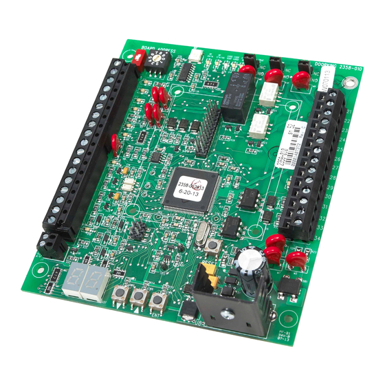
Use this manual for circuit board 2358-010 Revision B or higher.
For Models:
1833, 1835, 1837 and 1838 Multi-Door Access Controller
BOARD ADDRESS
ON
1
0
1
2
3
4
5
6
7
8
9
10
11
12
13
14
15
16
17
18
19
20
Date Installed:
Installer/Company Name:
Phone Number:
Leave Manual with Owner
UL 325 Compliant
RF
OUTPUT
ALARM
AUX
SECURE
RF
RF
CODE
CODE
CODE
RELAY
RELAY
RELAY
DATA
STATUS
SENT
GOOD
BAD
NC
NC
NO
NO
RESET
ENT
Copyright 2016 DoorKing, Inc. All rights reserved.
Tracker Expansion Board
Tracker Expansion Board
Tracker Expansion Board
Tracker Expansion Board
Provides Access Control System expansion to
2358-010
NC
NO
21
22
23
24
25
26
27
28
29
30
31
32
33
34
Circuit Board
Serial Number(s)
and Revision Letter:
Wiegand Compatable
manage Up to 24 additional Access Points.
Q u
a d
E n
B o
c l o
a r d
( N
s u
o t
r e
I n c
l u d
e d
)
S i n
g l e
E n
B o
c l o
w i
a r d
s u
t h
C a
r e
B u
r d
i l t -
R e
S i n
I n
( N
a d
o t
g l e
I n c
e r
E n
l u d
e d
c l o
)
( N
o t
2358-065-L-7-16
B o
a r d
s u
r e
I n c
l u d
e d
)
Advertisement
Table of Contents


Need help?
Do you have a question about the 1833 and is the answer not in the manual?
Questions and answers