Table of Contents
Advertisement
Quick Links
HARDwired Installation/
Owner's Manual
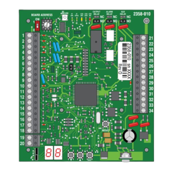
Use this manual for circuit board 2358-010 Revision "O" or higher.
For Access Control System Models:
1833, 1835, 1837 and 1838 Multi-Door Access Controller
This access control equipment must be installed inside of a controlled, protected or restricted area to comply with UL 294 certification.
BOARD ADDRESS
ON
1
0
1
2
3
4
5
6
7
8
9
10
11
12
13
14
15
16
17
18
19
20
The 1830 Series Access Control System's Relay Strike Time MUST
be set to "00" or the tracker expansion board will NOT function.
Date Installed:
Installer/Company Name:
Phone Number:
Leave Manual with Owner
Conforms To UL STD 294
Certified To CAN/ULC-S319-05
RF
OUTPUT
ALARM
AUX
SECURE
RF
RF
CODE
CODE
CODE
RELAY
RELAY
RELAY
DATA
STATUS
SENT
GOOD
BAD
NC
NC
NO
NO
RESET
ENT
Copyright 2019 DoorKing
Tracker Expansion Board
Tracker Expansion Board
Tracker Expansion Board
Tracker Expansion Board
Provides Access Control System expansion to
manage Up to 48 additional Access Points.
2358-010
NC
NO
21
22
23
24
25
26
27
28
29
30
31
32
33
34
Circuit Board
Serial Number(s)
and Revision Letter:
®
, Inc. All rights reserved.
Wiegand Compatable
2358-065 Issued 7-19
Q u
a d
E n
B o
c l o
a r d
( N
s u
o t
r e
I n c
l u d
e d
)
S i n
g l e
E n
B o
c l o
w i
a r d
s u
t h
C a
r e
B u
r d
i l t -
S i n
R e
I n
( N
a d
o t
g l e
I n c
e r
E n
l u d
B o
e d
c l o
)
( N
s u
o t
I n c
l u d
a r d
r e
e d
)
Version E
Advertisement
Table of Contents

Related Manuals for DoorKing 1830 Series


Summary of Contents for DoorKing 1830 Series
- Page 1 S i n g l e I n c l u d The 1830 Series Access Control System’s Relay Strike Time MUST c l o a r d be set to “00” or the tracker expansion board will NOT function.
-
Page 3: Table Of Contents
Access Control System shall issue credentials that will lead to access. DoorKing, Inc. reserves the right to make changes in the products described in this manual without notice and without obligation of DoorKing, Inc. to notify any persons of any such revisions or changes. -
Page 4: Section 1 - Tracker Expansion Board Introduction
Tracker expansion boards will interface with a variety of wiegand devices including card readers, RF transmitters, digital keypads, etc. The tracker expansion board will also report gate operator data from DoorKing intelligent gate operators that have Gate Tracker outputs. -
Page 5: General System Layout
Tracker Expansion Board (Optional) Board (Optional) Relay 2/Wiegand 2 Gate operator 1 data input: Gate Local Alarm Separate DoorKing slide, swing or overhead Operator 1 Auxiliary Relay Alarm Power operators only. Data Input Alarm Relay Gate Gate operator 2 data input:... -
Page 6: Tracker Expansion Board Overview
Communication ONLY to other tracker expansion boards. DO NOT connect to access control system. Gate Operator 1 Power Monitor Monitors 24V AC/DC power from DoorKing slide, swing or overhead gate operators. Wire polarity does NOT matter. Gate Operator 1 Power Monitor Gate Operator 2 Power Monitor Monitors 24V AC/DC power from DoorKing barrier gate operator. -
Page 7: Board Input Descriptions
Gate Operator Data Input Gate operator data inputs can only be used with DoorKing vehicular gate operators (see section 1.1). The tracker expansion board receives data (Terminals 1-5 and 11-14) from the gate operator control board, converts it to wiegand format, and then sends this wiegand data to the access control system where it is stored in the transaction buffer. -
Page 8: Setting Board Address (Software - System Relay)
1.6 Setting Board Address (Software - System Relay) When using tracker expansion boards connected to a single access control system, the board addresses on EACH tracker expansion board should be set so that the Remote Account Manager for Windows (V 6.4 or newer only) software can identify each tracker expansion board. -
Page 9: Relay Identification (Software - System Relay)
RS 232 1.7 Relay Identification (Software - System Relay) The models 1833, 1835, 1837 and 1838 access control systems each have THREE relays (Relay 0, 1, and 2). When the tracker expansion boards is added to this system, the Output Relay on the tracker expansion boards (Terminals 25-26) are identified in the software by the board address, beginning with board address 3 = System Relay 3 (System Relays 0, 1 and 2 are reserved for the access control board ELEVATOR relays ONLY in the software). -
Page 10: End-Of-Line Termination Jumper
1.8 End-of-Line Termination Jumper ONLY use the end-of-line termination jumper on the LAST board in each relay/wiegand connection (24 board maximum for each relay/wiegand connection). Note: Rev M or higher 2358 board. OUTPUT ALARM 2358-010 SECURE CODE CODE CODE RELAY RELAY RELAY BOARD ADDRESS... -
Page 11: Section 2 - Installation
(enclosures are optional and not included with the tracker expansion board). DoorKing has two enclosures available for this purpose. The small housing will hold a single tracker expansion board and the large housing can hold up to four tracker expansion boards. - Page 12 Example 3: 4000 ft total, ONLY one HARDwired communication line shown. 8 boards are connected to relay 2/wiegand 2. Zone addresses can be used if desired. tracker 100 ft 100 ft tracker 200 ft tracker expansion expansion expansion farthest board board board board...
- Page 13 Example 6: 4000 ft total, ONLY one HARDwired communication line shown. 8 boards with “Zones” are connected to relay 2/wiegand 2. tracker tracker tracker tracker 500 ft 600 ft 400 ft 500 ft expansion expansion expansion expansion board board board board address 3 address 3...
-
Page 14: Single Board Enclosure
2.2 Single Board Enclosure Optional single enclosure with a single tracker expansion board (P/N 2351-080) provides a lockable, weather resistant housing. 5.75” 3.625” Mounting Hole Optional Screw On Antenna Mounts for wireless kits ONLY. 8.75” RESET Mounting Hole 3/4” Conduit 2.375”... -
Page 15: Single Board Enclosure With Card Reader
1/2” 6.5” Knock-out Board Mount Mounting Note: 4.5” 5.25” Can be mounted on a DoorKing gooseneck mounting post. Optional Built-In Card Reader with Lighting: Antenna DK Prox Reader - P/N 1815-333 Mount Power Supply Note: The power supply that is... -
Page 16: Board Addresses 3-10 Communication Line Hardwiring
• Proper grounding is required! Ground wire should be a minimum 12 AWG. Important Wireless Note: Wireless kits ARE NOT 1830 Series wired like this. Refer to RS 232 wireless instructions with Access Control 1830’s relay... -
Page 17: Board Addresses 11-18 Communication Line Hardwiring
Auxiliary terminal power transformer on access conrol system board must be connected. Otherwise, RS-232, elevator control and wiegand inputs will not function. • Proper grounding is required! Ground wire should be a minimum 12 AWG. Note: Terminals can be removed 1830 Series Access Control from board for easy wiring. RS 232 System Board 1830’s relay... -
Page 18: Max Boards Communication Line Hardwiring
Board Board Board Board Address Address Address Address 1830 Series Access Control System Note: The 1830 series acces control system’s relay strike time MUST be programmed to “00” or tracker expansion boards Board Board Board Board Address Address Address Address will NOT function. -
Page 19: Basic Board Wiring Options At Access Point
3.5 Basic Wiring Options at Access Point Set Output Relay jumper on the tracker expansion board to N.O. (Normally Open) when using fail-secure (electric strike) locking device. Set Output Relay jumper on the tracker expansion board to N.C. (Normally Closed) when using fail-safe (magnetic lock) locking device. Set Output Relay jumper on the tracker expansion board to N.O. -
Page 20: Alarm Wiring Options At Access Point
3.6 Alarm Wiring Options at Access Point Note: Relay contacts (21-22; 23-24) are rated at 1A 30V maximum and can be set for Normally Open (N.O.) or Normally Closed (N.C.) operation. Terminals-#21 & #22 Aux Relay Jumper Terminals-#23 & #24 Alarm Relay Jumper Set Auxiliary Relay jumper typically (NO). -
Page 21: All Available Devices At Access Point
3.7 All Available Devices at Access Point Set Output Relay jumper on the tracker expansion board to N.O. (Normally Open) when using fail-secure (electric strike) locking device. Set Output Relay jumper on the tracker expansion board to N.C. (Normally Closed) when using fail-safe (magnetic lock) locking device. Set Output Relay jumper on the tracker expansion board to N.O. -
Page 22: Typical Dual Mode Wiring At 2 Access Points
3.8 Typical Dual Mode Wiring at 2 Access Points One tracker expansion board can be programmed (step 12, set to 1) to control 2 access points. The board Gate Operator Control Door Control address number that has been physically set on the tracker expansion board and the NEXT sequential board Electric strike address number will control the 2 access points. -
Page 23: Quad Box Wiring
ON/OFF Switch. Terminal Wire polarity does not matter. 4 Boards Power 16.5 VAC, 40 VA Required 18 GA. Wire 100 ft max 16 GA. Wire 200 ft max To DoorKing From From From From Card Reader Door Lock Access Control... -
Page 24: Gate Operator Data Wiring - Optional Control Wiring
(Tracked). The gate operators can also be controlled (Opened and closed) if desired by wiring the red dashed wires along with the black wires in the diagrams. Choose your specific gate operator model from the 6 diagrams shown on the next 3 pages. Only DoorKing gate operators shown in the 6 diagrams will function. - Page 25 6050, 6100, 6300 Swing Gate Operators 6 1 0 Output Relay Jumper “NO” OUTPUT ALARM 2358-010 SECURE CODE CODE CODE RELAY RELAY RELAY BOARD ADDRESS DATA STATUS SENT GOOD 4502-010 Dashed lines are ONLY required if the tracker expansion board is to OPEN the vehicular gate when a valid access code has been...
- Page 26 9200 Series, 9500 Slide Gate Operators Output Relay Jumper “NO” OUTPUT ALARM 2358-010 SECURE CODE CODE CODE RELAY RELAY RELAY BOARD ADDRESS DATA STATUS SENT GOOD Dashed lines are ONLY required if the tracker expansion board is to 4404-010 OPEN the vehicular gate when a valid access code has been received (Output relay...
- Page 27 AC Powered 6524 Swing / 9024 Slide Gate Operators ONLY Not for use with the SOLAR Powered 6524 or 9024. Dashed lines are ONLY required if the tracker AC Powered ONLY expansion board is to OPEN the vehicular Output Relay Jumper “NO” 1 2 3 4 5 6 7 8 9 10 gate when a valid SELF TEST...
-
Page 28: Section 4 - Programming
SECTION 4 - PROGRAMMING Before beginning any programming, the tracker expansion board MUST be completely wired and the board MUST have power. 4.1 LED and Button Descriptions RF SECURE - RF DATA Not used when board is HARDwired. These 5 LEDs are Not used when board RF STATUS Used with wireles communication ONLY (see wireless is HARDwired. - Page 29 Programming Options on EACH Board Select desired program steps and PHYSICALLY program EACH tracker expansion board being used with the access control system. “Basic programming sequence on EACH board” on previous page explains how to program the functions into the board. Program Selection Factory...
- Page 30 Aux Relay as 2nd Alarm Relay. Aux Relay will mirror Alarm Relay functions. Aux Relay as 2nd Alarm Relay, PULSE. Aux relay will Pulse during any Alarm Relay activation. Good Card: Aux Relay will activate for Aux Relay timer for any Access Granted Card Aux Relay Functions 0 - 12 Any Card: Aux Relay will activate for Aux Relay Timer when any card has been...
-
Page 31: Programming Step Descriptions
4.3 Programming Step Descriptions Program Step 1: Door Strike Timer Sets the amount of time the door lock will remain unlock after the Output Relay has been activated (Terminals 25 & 26). Program Step 2: Free Exit Timer, Strike Time Sets the amount of time the door lock will remain unlock after the Request to Exit has been activated (Input at terminal 18). - Page 32 4.3 Programming Step Descriptions Continued Program Step 15: Aux Relay Functions Sets how the Aux relay will function (Terminals 21 & 22). Set to 0, Aux relay is disabled. Set to 1, No door ajar timer has been set. Requires a door contact switch. Aux relay will activate when door is not closed. Set to 2, No door ajar timer has been set.
- Page 33 Program Step 22: Card Code Forwarding, Tracker as Repeater (Wireless ONLY) ONLY USE THIS FEATURE AS DIRECTED BY DOORKING TECH SUPPORT. Sets wireless tracker expansion board to operate as a wireless repeater and forward card codes (access codes) to the next board in the wireless system when the wireless signal range needs to be extended (ONLY works on WIRELESS tracker expansion board).
-
Page 34: Section 5 - Troubleshooting
SECTION 5 - TROUBLESHOOTING Before beginning any troubleshooting, check all wiring and look for any loose connections. Double check your wiring! The tracker expansion board in some applications may have over 20 wires connected directly to the board terminal strips. Be sure that you have a good VOM (Volt-Ohm-Meter) to assist you when checking voltages and continuity. -
Page 35: Gate Operator Data
5.2 Gate Operator Data Be sure that the gate operator has Gate Tracker capability. This can be determined by checking the revision letter of the control board in the operator. Gate operator control boards with Gate Tracker capability are listed below. •... -
Page 36: Gate Operator Event (Transaction) Reports
The tracker expansion interface board sends the following gate operator data to the DKS access control system. This data is stored in a separate file in the access control system and can be viewed by clicking the GATE button on the transaction report screen in the DoorKing Remote Account Manager for Windows software. -
Page 37: Complete System Information
5.4 Complete System Information Filling out this form will allow you to better keep track of the entire system at a glance. This will assist you when programming the system and/or any maintenance information about the system that may be required in the future. Board Address # 3-10 Relay 2 / Wiegand 2 Access Control System Connection Board Address #... - Page 38 5.4 Complete System Information Continued Filling out this form will allow you to better keep track of the entire system at a glance. This will assist you when programming the system and/or any maintenance information about the system that may be required in the future. Board Address # 11-18 Relay 1 / Wiegand 1 Access Control System Connection Board Address #...
- Page 39 2358-065 Issued 7-19 Version E...
-
Page 40: 2358-065 Issued
Provides Access Control System Expansion to 1833, 1835, 1837 and 1838 Multi-Door Access Controller Manage Up to 48 Additional Access Points. www.doorking.com Version E DoorKing, Inc. 120 S. Glasgow Avenue Conforms To UL STD 294 Inglewood, California 90301 U.S.A. Certified To CAN/ULC-S319-05...
Need help?
Do you have a question about the 1830 Series and is the answer not in the manual?
Questions and answers