Table of Contents
Advertisement
USER'S MANUAL
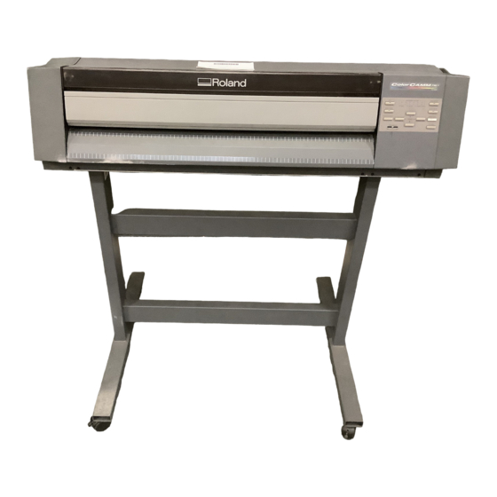
Thank you very much for purchasing the PC-600.
•
To ensure correct and safe usage with a full understanding of this product's perfor-
mance, please be sure to read through this manual completely and store it in a safe
location.
•
Unauthorized copying or transferral, in whole or in part, of this manual is prohibited.
•
The contents of this operation manual and the specifications of this product are
subject to change without notice.
•
The operation manual and the product have been prepared and tested as much as
possible. If you find any misprint or error, please inform us.
•
Roland DG Corp. assumes no responsibility for any direct or indirect loss or damage
which may occur through use of this product, regardless of any failure to perform on
the part of this product.
PC-600
Advertisement
Table of Contents

Subscribe to Our Youtube Channel
Related Manuals for Roland ColorCAMM PRO PC-600


Summary of Contents for Roland ColorCAMM PRO PC-600
- Page 1 If you find any misprint or error, please inform us. • Roland DG Corp. assumes no responsibility for any direct or indirect loss or damage which may occur through use of this product, regardless of any failure to perform on...
- Page 2 AVIS Cet appareil numérique de la classe A respecte toutes les exigences du Règlement sur le matériel brouilleur du Canada. ROLAND DG CORPORATION 1-6-4 Shinmiyakoda, Hamamatsu-shi, Shizuoka-ken, JAPAN 431-2103 MODEL NAME : See the MODEL given on the rating plate.
-
Page 3: Table Of Contents
IBM is a registered trademark of International Business Machines Corporation. COLORCHOICE ® is registered in the U. S. Patent Office. Other company names and product names are trademarks or registered trademarks of their respective holders. Copyright © 2000 Roland DG Corporation... -
Page 4: To Ensure Safe Use
Doing so may result in fire or electrical problem. shock. Immediately switch off first the sub power, then the main power, unplug the power cord from the electrical outlet, and contact your authorized Roland DG Corp. dealer or service center. - Page 5 Do not use with a damaged power Do not injure or modify the electrical cord or plug, or with a loose power cord, nor subject it to electrical outlet. excessive bends, twists, pulls, Use with any other binding, or pinching, nor place any power supply may object of weight on it.
- Page 6 Roll material must be placed at a Use the joining screws to secure the predetermined shaft position. unit to the stand. Failure to do so may Failure to do so result in falling of the may result in roll, leading to injury. falling of the unit, leading to injury.
-
Page 7: About The Labels Affixed To The Unit
About the Labels Affixed to the Unit These labels are affixed to the body of this product. The following figure describes the location. Do not allow hands or hair to come near the platen while the carriage is in motion. Do not touch the area around the printing carriage with the hands. -
Page 8: Pour Utiliser En Toute Sécurité
Le non-respect de cette consigne pourrait provoquer un incendie ou des décharges électriques. Couper immédiatement l'alimentation secondaire et ensuite l'alimentation principale. Débranchez le fil électrique et contacter votre revendeur ou votre centre de service de la société Roland DG autorisé. - Page 9 Ne pas utiliser avec une fiche ou un Ne pas endommager ou modifier le fil électrique endommagé ou avec fil électrique. Ne pas le plier, le une prise mal fixée. tordre, l'étirer, l'attacher ou le serrer Une négligence à de façon excessive. Ne pas mettre ce niveau pourrait d'objet ou de poids dessus.
- Page 10 Le rouleau doit être placé quand la Utiliser les vis fournies pour bien barre est en position adéquate. fixer l'appareil sur le support. Une négligence à ce Le non-respect de niveau pourrait cette consigne provoquer la chute du pourrait causer des rouleau et causer des défauts dans blessures.
-
Page 11: À Propos Des Étiquettes Collées Sur L'appareil
À propos des étiquettes collées sur l'appareil Ces étiquettes sont collées à l'extérieur de l'appareil. Les dessins suivants indiquent l'endroit et le contenu des messages. N' approchez pas vos mains ni vos cheveux du plateau de travail quand le chariot est en mouvement. Ne touchez pas avec les mains la zone située autour du chariot d' impression. -
Page 12: Chapter 1 - Introduction
Cleaning sheet Thermal transfer ribbon cartridge (resin) Alignment tool Brake Replacement blade for separating knife PC-600 DRIVER for Material for test cuts Cleaning pad Dust cover Roland ® Windows 98/95 COLORCHOICE ® CD-ROM Roland Notes on usage Quick reference guide ®... -
Page 13: Set-Up And Connections
Chapter 1 - Introduction 1-2 Set-up and Connections Ground the unit with the ground Do not use with any electrical power wire. supply that does not meet the Failure to do so may result in risk of ratings displayed on the unit. electrical shock in the even of a mechanical Use with any other power supply may lead problem. -
Page 14: For Ibm Pc Or Pc Compatibles
Chapter 1 - Introduction When arranging setup space for the PC-600, make sure you have a space that is at least 1500 mm (59-1/16 in.) wide, 750 mm (29-9/16 in.) in depth, and 1500 mm (59-1/16 in.) in height. Since the material moves during printing and cutting, make sure the unit is placed on a stable, sturdy surface. -
Page 15: Part Names And Functions
Chapter 1 - Introduction 1-3 Part Names and Functions Front View Printing carriage Front cover This is where a ribbon cartridge is mounted in Opening the front cover during printing or cutting causes operation to be the cartridge holder and printing is carried out. paused. -
Page 16: Rear View
Chapter 1 - Introduction Rear View Sheet Loading Lever Used to raise or lower the pinch rollers when loading or unloading material. Automatic setup is performed by loading material and lowering the lever. Power Connector (AC IN) This connector accepts standard AC power cord. -
Page 17: Operation Panel
Chapter 1 - Introduction Operation Panel * "Material setup" refers to the state when material has been loaded and the sheet-loading lever has been lowered. 12) BUSY LED 15) CARTRIDGE HOLDER LED 13) SETUP LED 14) FRONT COVER LED 1) POWER key 6) BASE POINT key 7) BASE POINT LED 2) POWER LED... -
Page 18: Led Display List
Chapter 1 - Introduction LED Display List : Lights up : Flashing – : Dark LED state PC-600 status and operator action CARTRIDGE FRONT DATA BASE ALIGN POWER SETUP BUSY HOLDER COVER CLEAR POINT POINT – – – – – –... -
Page 19: Installing The Driver
Chapter 1 - Introduction 1-4 Installing the DRIVER The screens shown in these steps are for windows 95. These screens may differ in places from the screens for windows 98, but the steps themselves are identical. - To perform printing or cutting from a software application, the appropriate software driver must be installed. - The file Readme.txt on the driver-installation disk contains late-breaking information that is not in the manual. -
Page 20: Installation
Chapter 1 - Introduction Installation ® ® Switch on the computer and start windows Insert the "PC-600 DRIVER for Windows 98 / 95" disk included with the unit. Click [Start]. Double-click the [Add Printer] icon. Point to [Settings], then click [Printers]. Double-Click Click Click [Next >] and follow the messages to complete... -
Page 21: Driver Setup
Chapter 1 - Introduction Driver Setup Use the driver to choose the output port for data. Click [Start]. Click the right mouse button on [Roland PC-600] Point to [Settings], then click [Printers]. and select [Properties]. Click the right mouse Click Click Click the [Details] tab and select a port. -
Page 22: Using Help
Available topics include details of the various settings as well as the "Printing and Cutting Guide" and "If you Think There's a Prob- lem.." Click [Start]. Click the right mouse button on [Roland PC-600] Point to [Settings], then click [Printers]. and select [Properties]. -
Page 23: Chapter 2 - Basic Operation
Chapter 2 - Basic Operation Chapter 2 - Basic Operation 2-1 Installing a Blade NOTICE When installing or removing a blade, make sure the sub power for the PC-600 is switched off and no material is loaded. When mounting the blade holder, do not depress the plate slide. Plate slide Do not touch the tip of the blade. - Page 24 Chapter 2 - Basic Operation When cutting is performed after printing, the cap tip of the blade holder may scratch the printed surface. If this is the case, lengthen the cutter blade extension. Removing a Blade 2) Remove the blade holder from the cutting carriage.
-
Page 25: Powering On
Chapter 2 - Basic Operation 2-2 Powering On Do not allow hands or hair to come near the platen while the carriage is in motion. Failure to do so may result in injury due to sudden movement of the carriage when the power is switched on/off, when the sheet loading lever is raised or lowered, or when the [CUT TEST] key, [SHEET CUT]... -
Page 26: Loading The Material
Chapter 2 - Basic Operation 2-3 Loading the Material Do not allow hands or hair to come Roll material must be placed at a near the platen while the carriage is predetermined shaft position. in motion. Failure to do so may result in falling of the Failure to do so may result in injury due to roll, leading to injury. - Page 27 Chapter 2 - Basic Operation * Only when using rolled material Pass the stopper onto the shaft to match the width of Stopper retaining screws the roll material to be used. (The shafts (2 pieces), stoppers (2 pieces), and stopper retaining screws (2 Shaft pieces) are included with the stand.) When fitting the stoppers onto the shaft, loosen the...
- Page 28 Chapter 2 - Basic Operation Side view of loaded roll material When using a thick roll of When only a small amount material of material remains Not OK (material diameter is 72 mm (2-7/8 in.) or less)... Shafts Shafts Shafts Position so that the left-hand edge of the material lies over any one of the grit rollers.
- Page 29 Chapter 2 - Basic Operation Lower the sheet loading levers to secure the material in place. When the sheet loading lever is lowered, the carriage begins to move. Setup is The width of the material is detected, and the finished. carriage stops at the material's right-hand edge.
- Page 30 Chapter 2 - Basic Operation Loadable material widths and pinch-roller positions : Grit roller : Pinch roller (left) : Pinch roller (right) Approx.160 mm (6-1/4 in.) Approx.320 mm Material (12-9/16 in.) Approx.460 mm (18-1/16 in.) Approx.610 mm (24 in.) Position of the Position of the Position of the Position of the...
-
Page 31: To Perform Long Printing/Cutting
Chapter 2 - Basic Operation To Perform Long Printing/Cutting When performing printing or cutting over a length of 1 m (39-3/8 in.) or more, first feed out the required length of material. Then follow the steps below to load the material. If the setting for enabling the prefeed function has been made on the PC-600, then skip steps 6 and 7. -
Page 32: Cut Test
Chapter 2 - Basic Operation 2-4 Cut Test Do not allow hands or hair to come near the platen while the carriage is in motion. Failure to do so may result in injury due to sudden movement of the carriage when the power is switched on/off, when the sheet loading lever is raised or lowered, or when the [CUT TEST] key, [SHEET CUT]... -
Page 33: Installing A Ribbon Cartridge
Chapter 2 - Basic Operation 2-5 Installing a Ribbon Cartridge NOTICE Ribbon cartridges must be installed in cartridge holders, and not mounted directly on the printing carriage. Do not allow the marker seals on the ribbon cartridges to be soiled or scratched. Such damage may result in faulty operation. -
Page 34: Installing Ribbon Cartridge
Chapter 2 - Basic Operation Installing Ribbon Cartridge When installing a new ribbon cartridge, remove the Take up slack in the in ribbon as shown in the stopper. figure. Side B Turn with a pencil or the like - Do not attempt to rewind the ink ribbon. Rewinding the ink ribbon may cause it to break. -
Page 35: Replacing An Ink Cartridge
Chapter 2 - Basic Operation Replacing an Ink Cartridge If an ink ribbon runs out while printing is in progress, the CARTRIDGE HOLDER LED flashes. Follow the steps below to replace with a new ribbon cartridge. If the ink ribbon runs out, operation stops and the Open the front cover and replace with a new ribbon warning beep sounds. -
Page 36: Self-Test
Chapter 2 - Basic Operation 2-6 Self-test Do not allow hands or hair to come near the platen while the carriage is in motion. Failure to do so may result in injury due to sudden movement of the carriage when the power is switched on/off, when the sheet loading lever is raised or lowered, or when the [CUT TEST] key, [SHEET CUT]... -
Page 37: Downloading Printing/Cutting Date
Chapter 2 - Basic Operation 2-7 Downloading Printing/Cutting Date NOTICE When printing a line that is horizontal with respect to the direction of material feed, set the line width to 0.15 mm (0.0059 in.) or more. Printing with a line width less than 0.15 mm (0.0059 in.) may cause the ink ribbon to snap. -
Page 38: Cutting Off Or Detaching The Material
Chapter 2 - Basic Operation 2-9 Cutting Off or Detaching the Material Do not allow hands or hair to come near the platen while the carriage is in motion. Failure to do so may result in injury due to sudden movement of the carriage when the power is switched on/off, when the sheet loading lever is raised or lowered, or when the [CUT TEST] key, [SHEET CUT]... -
Page 39: Powering Off
Chapter 2 - Basic Operation 2-10 Powering Off When not in use for prolonged periods, unplug the power cord from the electrical outlet. Failure to do so may result in danger of shock, electrocution, or fire due to deterioration of the electrical insulation. -
Page 40: When Not In Use
Chapter 2 - Basic Operation When Not in Use Place the included dust cover over the machine. This prevents dust from accumulating on the machine and the material. Storing Material When storing material, place it in plastic bags to protect it from dust and grime. -
Page 41: Chapter 3 - User's Reference
Displaying the Driver Setting Screen To make the settings for the driver, open Properties. To open Properties, use the printing menu for the program you're using to set the printer to [Roland PC-600], then click [Properties]. Setting the Material Size At the [Size] tab, make the setting for the size of the loaded material. - Page 42 Chapter 3 - User's Reference Setting the Cutting Parameters At the [Cutting] tab, select the cutting line and make the setting for the cutting speed. Bitmap data is printed, without performing cutting. Make cutting lines using vector data. Choose the cutting method. Specify the cutting line by color or line type.
- Page 43 Chapter 3 - User's Reference To use a special color, choose the color to use from [Special], then associate the image color (the color you specified using the program) with an ink ribbon. Install an ink-ribbon cartridge of the color you chose in the PC-600.
- Page 44 Chapter 3 - User's Reference Setting the Operating Parameters At the [Driver Options] tab, make the settings for the machine's operating parameters for other than printing and cutting. To use the settings on the PC-600 and not use the driver settings, choose [Enable Machine Settings]. To use the driver settings, choose [Enable Driver Settings] and make the settings for each item.
-
Page 45: Settings (Making Settings On The Pc-600)
® If you're using Roland COLORCHOICE , make the settings on the PC-600. The settings for this item cannot be made on Roland COLORCHOICE ®... - Page 46 Chapter 3 - User's Reference Making the Settings 1) Hold down the [ALIGN POINT] key on the panel while you turn the [POWER] key (sub power) on. The ALIGN POINT LED and the POWER LED lights up. 2) Pressing the keys changes the displayed CARTRIDGE HOLDER LEDs.
-
Page 47: Other Functions
Chapter 3 - User's Reference 3-3 Other Functions Setting the Base Point – Printing/Cutting at the Desired Location – The BASE POINT key is used to set the base point for printing or cutting. The base point can be set anywhere you like on the material, making it possible to print or cut unused portions of the material. The base point can be set after finishing material setup (and lowering the sheet loading lever). -
Page 48: Setting The Crop Marks, Base Point, And Align Point
Chapter 3 - User's Reference Setting the Crop Marks, Base Point, and Align Point – Remove the Printed Material, then Reload the Material and Perform Cutting – This feature is for performing position alignment in cases where printing is performed, after which the material removed from the machine for further processing (such as laminating), then again loaded on the machine for cutting. -
Page 49: Tips And Tricks For Printing/Cutting
Chapter 3 - User's Reference Remove the alignment tool from the cutting carriage Send the cutting data from the computer. and install the blade holder. 3-4 Tips and Tricks for Printing/Cutting Removing the Blank Space Surrounding a Picture Cutting outline Material Stick Adding Color to a Border... -
Page 50: Correcting Line Pitch
Chapter 3 - User's Reference Correcting Line Pitch How to Correct Line Pitch 1) Hold down the [BASE POINT] key on the panel while you turn the [POWER] key (sub power) on. The BASE POINT LED and the POWER LED lights up. 2) Pressing the keys changes the displayed CARTRIDGE HOLDER LEDs. -
Page 51: About The Printing/Cutting Area
Chapter 3 - User's Reference 3-5 About the Printing/Cutting Area ..Printing/Cutting area ..Crop mark Factory default When front edge sense is enabled 55 mm (2-3/16 in.) 55 mm (2-3/16 in.) Pinch roller (left) Pinch roller (left) 16 mm 12 mm 68 mm 16 mm... -
Page 52: About The Blade
Chapter 3 - User's Reference 3-6 About the Blade If the Blade Becomes Dull When the blade starts to lose its sharpness, try gradually increasing the cutter force. Increasing the cutter force temporarily allows the blade to perform better. However, once the blade is dull, it is time to replace it. Average Blade Life The life of a blade varies, depending on the amount of cutting it performs. -
Page 53: How To Replace The Separating Knife
Chapter 3 - User's Reference How to Replace the Separating Knife Make sure the power to the unit is Do not touch the tip of the blade off before attempting to replace the with your fingers. Doing so may result in injury. separating knife. -
Page 54: Care And Maintenance
Chapter 3 - User's Reference 3-7 Care and Maintenance Do not touch the area around the printing carriage with the hands. Failure to do so may result in burns. NOTICE Be sure to switch off the main power for the PC-600 before attempting to clean the unit and platen or using head cleaner to clean the printing head. -
Page 55: How To Use The Cleaning Sheet
Chapter 3 - User's Reference How to Use the Cleaning Sheet The following details the correct usage of this cleaning sheet. Failure to observe the following points may result in damage to the machine. • Do not use any cleaning sheet that has a damaged surface such as cuts, tears or creases. •... -
Page 56: Cleaning The Main Unit
Chapter 3 - User's Reference Lower the sheet loading lever. When the front cover is closed, the BUSY LED If the material is not loaded at the correct location, flashes and head cleaning starts. the SETUP LED flashs at the same time. Head cleaning is finished when the BUSY LED If this happens, reload the material at the proper goes dark. -
Page 57: Cleaning The Cleaning Pad
Chapter 3 - User's Reference Cleaning the Cleaning Pad If the cleaning pad becomes dirty, clean it gently using a commercially available brush (item with soft fibers) or the like. The Cleaning Pad If the cleaning pad on the left edge of the unit's front surface is damaged, the printing head may be destroyed. If the cleaning pad is damaged by a blade or the like, replace it with a new cleaning pad. -
Page 58: What To Do If
If this does not correct the problem, then check the flashing To cancel the sleep mode, send data from the computer or LEDs and contact your authorized Roland DG Corp. dealer or press any key on the operation panel. service center. - Page 59 30 minutes to an hour. Contact your authorized Roland DG Corp. dealer or service The amount of time required for acclimation varies according center for replacement of the printing head.
- Page 60 Chapter 3 - User's Reference Cartridge detection is incorrect The material slips away from the pinch rollers during operation Has a marker seal on a ribbon cartridge become dirty? Is the loaded material straight, and not at an Wipe off any grime on marker seals. angle? If the loaded material is crooked, it may come loose from the Are ribbon cartridges designed exclusively for the...
- Page 61 Chapter 3 - User's Reference Is the brake installed? When performing long printing or If the included brake is not attached, then install it (see "2-3 cutting, operation stopped before Loading the Material"). If the settings on the machine have been made to set the printing or cutting finished prefeed function to [ENABLE], then before performing printing or cutting, the length of material required for output is...
- Page 62 Chapter 3 - User's Reference When performing continuous The Material is not cut properly printing, the image quality Are the blade and blade holder installed correctly changes or margins are grimy and securely? Install these so that there is no looseness (see “2-1 Installing a When you perform continuous printing, image quality may Blade”).
-
Page 63: Specifications
(blade holder and pin), material for test cuts, head cleaner, alignment tool, brake, replacement blade for separating knife, cleaning sheet, cleaning pad, dust cover, PC-600 DRIVER ® ® for Windows 98/95, Roland COLORCHOICE CD-ROM, user’s manual (this manual), ® notes on usage, quick reference guide, Roland COLORCHOICE installation guide... - Page 64 Chapter 3 - User's Reference Interface specifications Parallel Standard Bidirectional parallel interface (compliant with IEEE 1284: nibble mode) Input signals STROBE (1BIT), DATA (8BITS), SLCT IN, AUTO FEED, INIT Output signals BUSY (1BIT), ACK (1BIT), FAULT, SLCT, PERROR Level of input output signals TTL level Transmission method Asynchronous...
- Page 65 The enclosed Roland product is a single user version.
Need help?
Do you have a question about the ColorCAMM PRO PC-600 and is the answer not in the manual?
Questions and answers