
Related Manuals for Intelix ASW-WP


Summary of Contents for Intelix ASW-WP
- Page 1 ASW-WP Installation and Operation Guide Rev 140115 8001 Terrace Ave Phone: 608-831-0880 Suite 201 Toll-Free: 866-462-8649 Middleton, WI 53562 Fax: 608-831-1833...
-
Page 2: Important Safety Instructions
Do not block the air ventilation openings. Only mount the equipment per Intelix’s instructions. Use only with the cart, stand, table, or rack specified by Intelix or sold with the equipment. When/if a cart is used, use caution when moving the cart/equipment combination to avoid injury from tip-over. -
Page 3: Table Of Contents
ASW-WP Installation Guide Table of Contents Important Safety Instructions ........................2 Overview ............................... 4 Package Contents ..........................4 Front Panel ............................5 Rear Panel ............................6 Installation Instructions ..........................7 Basic Installation ..........................7 Twisted Pair Output ......................... 8 Contact Closure Inputs ........................8 Device Power ........................... -
Page 4: Overview
“last in” will be selected. There are additional contact closure inputs provided on the rear of the unit to allow third party control. RS232 control of the ASW-WP can be accomplished by connecting to the RS232 port on a compatible receiver, such as a DIGI-HD60C-R. -
Page 5: Front Panel
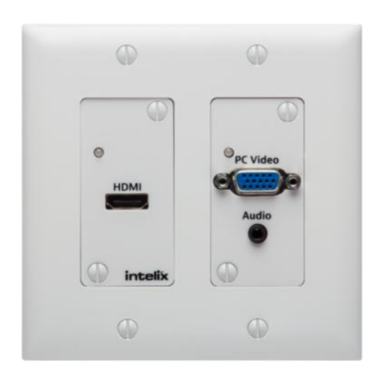
ASW-WP Installation Guide Front Panel HDMI Input PC Input Status LED Status LED PC Video HDMI Input and Audio Input HDMI Input status LED – Indicates power, active signal, and selected input for the HDMI input. (p. 11) PC Input status LED – Indicates power, active signal, and selected input for the PC Video input. -
Page 6: Rear Panel
Dry contact inputs – Inputs for mechanical switches or relays to provide manual input selection control Aux power input – 5vDC 2a input to power the ASW-WP. It is not necessary to connect power when using a compatible receiver with PoE (Power over Ethernet) such as the DIGI-HD60C-R. -
Page 7: Installation Instructions
ASW-WP Installation Guide Installation Instructions Basic Installation This diagram shows the most basic application for the ASW-WP. Follow the instructions below for installation of this system. 1. Turn off power and disconnect the audio/video equipment by following the manufacturer’s instructions. -
Page 8: Twisted Pair Output
Contact Closure Inputs The ASW-WP includes dry contact closure (C.C.) inputs to allow different types of manual switching. These C.C. inputs are intended to be connected directly to relays or switches. To activate, simply short the associated terminal to the “GND” terminal. The ASW-WP ships from the factory with a jumper in place between the “AUTO”, and “GND”... -
Page 9: Device Power
ASW-WP Installation Guide Device Power The ASW-WP supports [2] types of power input: PoE and rear panel input. When using PoE, a compatible HDBaseT receiver can power the ASW-WP by inserting power onto the twisted pair cable. When using a compatible receiver (such as the DIGI-HD60C-R), there is no need to use the rear panel power input. -
Page 10: Basic Operation
(Fn+F8 twice) on the HDMI laptop, the video output will be disabled, and the ASW-WP will select the VGA input. To return to the HDMI input, press (Fn+F8 twice) to enable the video output. Depending on the laptop manufacturer, this operation may alter slightly. -
Page 11: Led Indicators
An essential part of operation is the EDID table, which is transmitted to the source via HDMI cable from the ASW-WP HDMI input. The ASW-WP units feature a pass through EDID mode for the HDMI and VGA inputs. The preferred native timing of the display will be transmitted to the source. -
Page 12: Hdcp Management
1024x768, 2ch audio HDCP Management The ASW-WP offers advanced HDCP management to allow greater compatibility with other devices. The output will always be encrypted or unencrypted, following the status of the source content (if the content is encrypted, the output of the HDBaseT receiver will be encrypted;... -
Page 13: Low Power Mode
ASW-WP. The wake up process takes between 6-10 seconds. 1. No video – If the ASW-WP detects no video on either the HDMI or the VGA input for a set amount of time, the ASW-WP will go into low-power mode. The default time is 30 minutes, which can be adjusted by using the Display Control Software or sending an RS232 command. -
Page 14: Rs232 Connection
ASW-WP with a 3 party control system: 9600 baud 8 Data Bits 1 Stop Bit Parity = none Below are some diagrams to assist you in the pin out between standard PC COM ports and HDBaseT receivers that are compatible with the ASW-WP:... -
Page 15: Rs232 And Tcp/Ip Commands
<LF> = Line Feed (Hex 0A) <SP> = Space (Hex 20) *NOTE: You must turn Display Control OFF in order to gain control of the ASW-WP via RS232 – please send the “Display Control OFF” command first! (See page 16) -
Page 16: Display Control Commands
ASW-WP Installation Guide Display Control Commands Description Command Response Turn Display Control ON DFG1<CR><LF> No response Turn Display Control OFF DFG0<CR><LF> No response Store the ON command for No response DON(xx)<SP><CR><LF> Display Control (xx = up to 20 Example: characters) DONpwron<SP><CR><LF>... -
Page 17: Display Control Software
“Power ON” command, followed by the “Input Select” command. When the ASW-WP times out due to lack of video or activity, it will send the preprogrammed “Power Off” command. This will effectively synchronize the power states of the display and the ASW-WP, eliminating the need for a 3 party control system in many systems. - Page 18 ASW-WP Installation Guide 3. Open the Intelix Display Control software. 4. Adjust the COM Port to match the PC COM port – it is usually COM1, unless you are using a USB to Serial adapter. To find the COM port your USB to serial port adapter is using –...
- Page 19 ASW-WP Installation Guide Select Device Manager Under “Ports (COM & LPT1) you should see your adapter listed. The COM port it consumes will be listed next to the name. 5. Enter the “POWER ON”, “POWER OFF”, and “INPUT SELECT CODE”...
- Page 20 ASW-WP Installation Guide 7. Press the green “Thumbs Up!” button or Test -> Perform Test 8. Test the commands you entered by monitoring the display status. 9. Select the “Time Between Commands” from the drop down window. This sets the amount of time the controller will wait after it sends the “Power On”...
- Page 21 ASW-WP Installation Guide 10. Select the “No Signal Power Off” and “No Activity Power Off” timeouts from the drop down windows. For more information on these selections – see “Low Power Mode” on p. 13. 11. Save your configuration disconnect the serial cable from the...
- Page 22 ASW-WP Installation Guide 12. Connect the ASW-WP to an HDBaseT receiver with an RS232 port (DIGI-HD60C-R) and power the devices. 13. Connect your PC COM port to the RS232 port on the HDBaseT receiver. See p. 14 for more information on RS232 connections.
-
Page 23: Troubleshooting
Unplug signal cable, and replug. PC Audio distorted Turn volume down on your PC. No video from HDBaseT output Verify the link LEDs on the receiver and the back of ASW-WP are lit; if not, check the twisted pair cable. -
Page 24: Technical Specifications
ASW-WP Installation Guide Technical Specifications Technical Specifications I/O Connections HDMI Input One (1) HDMI Type A Receptacle (Front) VGA Input One (1) Female PC Video HD-15-F Connector (Front) PC Stereo Audio One (1) 3.5 mm TRS Receptacle (Front) HDBaseT Port... - Page 25 HDBaseT Receiver (A/V Only) Compatibility DIGI-HD70-R Distances and picture quality may be affected by cable grade, cable quality, source and destination equipment, RF and electrical interference, and cable patches. Intelix specifications are based on straight-through cabling with standard-grade Cat 5e unless noted otherwise.
- Page 26 ASW-WP Installation Guide...
- Page 27 ASW-WP Installation Guide...
- Page 28 ASW-WP Installation Guide...
Need help?
Do you have a question about the ASW-WP and is the answer not in the manual?
Questions and answers