Table of Contents
Advertisement
Quick Links
Advertisement
Table of Contents

Subscribe to Our Youtube Channel
Related Manuals for Intelix AS-1H1V


Summary of Contents for Intelix AS-1H1V
- Page 1 AS-1H1V Installation and Operation Guide AS-1H1V HDMI/VGA Auto-Sw tch F rmw re HDCP HDMI Auto HDMI HDBT HDMI Out HDMI In VGA In Cont ct RS232 24V DC Rev 160415 11675 Ridgeline Dr. Toll-Free: 800-530-8998 Colorado Springs, CO 80921 Fax: 719-260-0075...
-
Page 3: Important Safety Instructions
AS-1H1V Installation Guide Important Safety Instructions 1. Read these instructions – All the safety and operating instructions should be read before this product is operated. 2. Keep these instructions – The safety and operating instructions should be retained for future reference. - Page 4 AS-1H1V Installation Guide 26. When the apparatus is not in use or during its relocation, take care of the power cord and plugs; e.g. tie up the power cord with cable tie or similar. The tie must be free from sharp edges and the like that might cause abrasion of the power cord.
-
Page 5: Table Of Contents
AS-1H1V Installation Guide Table of Contents Important Safety Instructions ��������������������������������������������������������������������������������������������������������������������������� Product Overview ��������������������������������������������������������������������������������������������������������������������������������������������� Package Contents ��������������������������������������������������������������������������������������������������������������������������������������������� Front and Rear Panels ��������������������������������������������������������������������������������������������������������������������������������������� Front Panel ���������������������������������������������������������������������������������������������������������������������������������������������������������� Rear Panel ����������������������������������������������������������������������������������������������������������������������������������������������������������� Installation Instructions ���������������������������������������������������������������������������������������������������������������������������������� Basic Installation ����������������������������������������������������������������������������������������������������������������������������������������������� HDBaseT Cabling Requirements ������������������������������������������������������������������������������������������������������������������������ Contact Closure Inputs ��������������������������������������������������������������������������������������������������������������������������������������... - Page 6 AS-1H1V Installation Guide RS232 Control ������������������������������������������������������������������������������������������������������������������������������������������������� Switching Commands ���������������������������������������������������������������������������������������������������������������������������������������� Power Management ����������������������������������������������������������������������������������������������������������������������������������������� HDCP Compliance ��������������������������������������������������������������������������������������������������������������������������������������������� Device Baud Rate ���������������������������������������������������������������������������������������������������������������������������������������������� Device Information �������������������������������������������������������������������������������������������������������������������������������������������� Factory Reset����������������������������������������������������������������������������������������������������������������������������������������������������� EDID Configuration ������������������������������������������������������������������������������������������������������������������������������������������� VGA Scaling Configuration �������������������������������������������������������������������������������������������������������������������������������� Display Control Settings ������������������������������������������������������������������������������������������������������������������������������������ Display Control Queries ������������������������������������������������������������������������������������������������������������������������������������� Display Control Hex Commands ������������������������������������������������������������������������������������������������������������������������...
-
Page 7: Product Overview
3 hours by default. The AS-1H1V will detect which input has an active video input, and switch to that input – if both inputs are active, the “last in” will be selected. There are additional contact closure inputs provided on the rear of the unit to allow third party control. -
Page 8: Front And Rear Panels
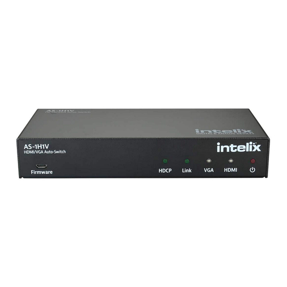
AS-1H1V Installation Guide Front and Rear Panels Front Panel AS-1H1V HDMI/VGA Auto-Sw tch F rmw re HDCP HDMI Micro USB port for firmware updating HDCP status LED HDBaseT Link status LED VGA input status LED HDMI input status LED Power LED... -
Page 9: Installation Instructions
Connect shielded Category 5E or greater twisted pair cable with the TIA/EIA-568B crimp pattern between the transmitter (AS-1H1V) and the HDBaseT receiver. If the HDBaseT receiver cannot provide power to the AS-1H1V or the receiver requires remote power, connect the included power supply to the 24V DC power input of the device. -
Page 10: Contact Closure Inputs
“GND” terminal. Normally open, momentary switches should be used. The AS-1H1V ships from the factory with a jumper in place between the “AUTO”, and “GND” terminals; this should remain in place if you wish the unit to switch automatically when a video signal is present. -
Page 11: Device Power
RS232 through the HDBaseT receiver. To use the RS232 extension capabilities of the AS-1H1V, connect the TX, ground, and RX control signal wires to the removable 3-pole terminal block. Consult the manual of the control device(s) to determine which pins the TX and RX signals are carried on. -
Page 12: General Operation
General Operation Automatic Switching By placing a jumper between the “Auto” and “Gnd” terminals on the back of the AS-1H1V, the unit will switch inputs by sensing an active video signal. The AS-1H1V will switch automatically to the “last in” connected input. For example, if an VGA signal is currently displayed, and then connect an HDMI source, the unit will switch to the HDMI input. -
Page 13: Firmware Port
VGA EDID and Scaling The AS-1H1V features a single EDID setting for the VGA input of 1366x768. An analog video scaler in the device will scale the video content to many common video resolutions up to WUXGA (1920x1200). Since the content will always be scaled, there are options to change the scaling to either fit the original content to the scaled video output or fill the display with the video content. -
Page 14: Hdcp Management
No Signal If the AS-1H1V detects no video on either the HDMI or the VGA input for a set amount of time, the AS-1H1V will go into low-power mode. The default time is 30 minutes, which can be adjusted by using the Display Control Software or sending an RS232 command. -
Page 15: Display Control Functionality
Display Control Functionality The AS-1H1V may be used to control power and input status of the LCD or Projector connected to an HDBaseT receiver. When the AS-1H1V is “woken up from low-power mode, it will send the preprogrammed “Power On”... - Page 16 GET AUTO<CR><LF> Get Auto-switching state AUTO ON!<CR><LF> OR AUTO OFF!<CR><LF> Power Management In addition to going to a low-power mode when using the Display Control functions, the AS-1H1V can also be set to this mode via RS232. Description Command Response STANDBY<CR><LF>...
- Page 17 AS-1H1V Installation Guide HDCP Compliance Description Command Response HDCP ON<CR><LF> HDCP ON!<CR><LF> HDCP Compliance ON HDCP OFF<CR><LF> HDCP OFF!<CR><LF> HDCP Compliance OFF GET HDCP<CR><LF> Get HDCP Compliance status HDCP ON! <CR><LF> OR HDCP OFF!<CR><LF> Device Baud Rate The default baud rate for the AS-1H1DP is 9600. This can be changed to accommodate various installation needs: 2400, 4800, 9600, 19200, 38400, 57600, 115200.
- Page 18 AS-1H1V Installation Guide EDID Configuration The EDID settings listed below will only be passed to the HDMI input. Description Command Response EDID UHD<CR><LF> EDID UHD!<CR><LF> UHD/30 EDID FHD<CR><LF> EDID FHD!<CR><LF> 1080p EDID HD<CR><LF> EDID HD!<CR><LF> 720p EDID WUXGA<CR><LF> EDID WUXGA!<CR><LF>...
- Page 19 AS-1H1V Installation Guide Display Control Settings Description Command Response DFG1 DFG1!<CR><LF> Turn Display Control ON Display Control On<CR><LF> DFG0 DFG0!<CR><LF> Turn Display Control OFF Display Control Off<CR><LF> DONxx DON!<CR><LF> Store the ON command for Display Example: pwron<CR> Control (xx = up to 25 characters) DONpwron <CR><LF>...
- Page 20 AS-1H1V Installation Guide Display Control Queries The query responses will be identical to the Display Control commands entered into the device. Description Command Response DFG? Display Control state? DFG1<CR> OR DFG0<CR> DON? DONpwron<CR> Display On command? DOF? DOFpwroff<CR> Display Off command? DIS? DIShdmi1<CR>...
- Page 21 AS-1H1V Installation Guide Troubleshooting Device does not power on Apply an active video signal; the unit may be in standby mode. » Transmit the WAKE command via RS232. » If using a receiver with PoH, verify that the receiver is powered.
- Page 22 Reset Switch Microswitch Available Models AS-1H1V-W (White Faceplate and Painted Insert), AS-1H1V-B (Black Faceplate and Painted Insert) Included Accessories Installation Guide, Power Supply, Two (2) 4-pin Removable Screw Terminals, RS232 cable (3-pin to DE9), 2-pin Removable Screw Terminal, USB Programming Cable...
- Page 23 AS-1H1V Installation Guide...
- Page 24 Intelix is a brand of: 11675 Ridgeline Drive Colorado Springs, Colorado 80921 USA Phone: 719-260-0061 Fax: 719-260-0075 Toll-Free: 800-530-8998...
Need help?
Do you have a question about the AS-1H1V and is the answer not in the manual?
Questions and answers