
Subscribe to Our Youtube Channel
Related Manuals for Brother S-7300A


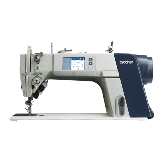
Summary of Contents for Brother S-7300A
- Page 1 S-7300A SERVICE MANUAL Please read this manual before making any adjustments. SINGLE NEEDLE DIRECT DRIVE LOCK STITCHER WITH ELECTRONIC FEEDING SYSTEM AND THREAD TRIMMER...
- Page 2 This service manual is intended for S-7300A; be sure to read the S-7300A instruction manual before this manual. Carefully read the “SAFETY INSTRUCTIONS” below and the whole of this manual to understand this product before you start maintenance. As a result of research and improvements regarding this product, some details of this manual may not be the same as those for the product you purchased.
- Page 3 ) indicates something that you must do. The picture inside the circle indicates the · · · · · nature of the thing that must be done. (For example, the symbol at left means “you must make the ground connection”.) S-7300A...
- Page 4 Contact your Brother dealer or a qualified electrician for any electrical work that may need to Secure the table so that it will not move when tilting be done.
- Page 5 If the machine develops a problem, contact your When replacing the bobbin and needle nearest Brother dealer or a qualified technician. When not using the machine and when leaving the machine unattended Do not hold the machine head by the panel when tilting it back or returning it to its original position.
- Page 6 If only one hand is used, the weight of the machine Ask your Brother dealer or a qualified electrician to head may cause your hand to slip, and your hand carry out any maintenance and inspection of the may get caught.
- Page 7 The following warning labels appear on the sewing machine. Please follow the instructions on the labels at all times when using the machine. If the labels have been removed or are difficult to read, please contact your nearest Brother dealer. Touching areas where high voltages are present can Be careful not to get your hands result in severe injury.
- Page 8 Transformer box (100 V/400 V system only) Oil tank Control box 0874D S-7300A...
- Page 9 S-7300A...
-
Page 10: Table Of Contents
5-10. Hand switch and X-over seam sensor ..60 6-14. Stand ............96 5-10-1. Cord holder and Thread wiper 6-15. Needle and presser foot ......97 device assembly ....... 60 6-16. Hand switch and X-over seam sensor ..98 S-7300A... - Page 11 7-8. Adjusting the thread take-up amount 11-2. List of error codes ........181 (-[][]3 specifications) ........130 7-9. Adjusting the presser foot floating amount (minute lifting amount) (option) ...... 131 7-10. Adjusting the thread tension and tension release wire ........... 132 S-7300A...
-
Page 12: Machine Specifications
0.8mm 1.2mm Needle (DB×1, DP×5) #11 - #18 #19 - #22 Motor AC servo motor Control circuit Microprocessor Rotary hook New lubrication-type rotary hook Lubricating oil -[]0[][] -[]3[][] Rotary hook High-speed spindle High-speed spindle Needle bar Special Brother grease S-7300A... -
Page 13: Notes On Handling
1. Clear away any tools, etc. which may be near the table holes. 2. While holding the face plate with your left hand, gently return the machine head to the upright position with your right hand. * Do not hold the operation panel. 0879D S-7300A... -
Page 14: Function Settings
・“7-12. Setting method for standard depression strokes”. ・“7-4. Adjusting the upper shaft reference position”. ・“7-5. Adjusting the feed (position, maximum pitch, vertical movement, etc.)”. ・“7-13. Adjusting the X-over seam sensor”. “3-12. Serial number checking method”. “7-14. Touch key adjustment”. S-7300A... - Page 15 3. FUNCTION SETTINGS Turn on power. S-7300A 303P If the power is turned on without any key operations 1202D S-7300A...
-
Page 16: Memory Switch Setting Method (Advanced)
<Memory switch setting mode exiting method> ・ Press the return key to return to the special menu screen. <Special menu exiting method> At the special menu screen, press the home key to close the special menu ・ and switch to the home screen. S-7300A... -
Page 17: List Of Memory Switch Settings
(*) If MSW-051 is set to "ON", thread trimming pedal operation is disabled after the presser foot lifter pedal has been operated during standing operation. OFF: No operation (only possible using presser foot lifter pedal) (*1) For other than Europe and America For Europe and America S-7300A... - Page 18 Presser foot operation when treadle is depressed forward to 1st step - (*) Displayed when MSW-852 is set to "ON" ON: Presser foot is lowered OFF: Presser foot is not lowered (*2) For other than Europe and America: ON For Europe and America: OFF S-7300A...
- Page 19 Sewing motor high speed range reaching point (S4) for standing up variable speed pedal. Treadle speed curve 0~3 0: Constant Speed 1: Curves downward 2: Curves upward 3: S line curve Depression stroke (*3) For Japan: -5 For other than Japan: 0 Speed Treadleb backward Depression stroke Neutral stroke S-7300A...
- Page 20 (*) When a larger value is set, the deceleration of the sewing machine motor becomes faster. When a smaller value is set, the deceleration of the sewing machine motor becomes slower. -3~6 Gain during high-speed motor operation -3~6 Gain during low-speed motor operation -3~9 Gain during thread trimming S-7300A...
- Page 21 MSW-181. (*4) -3 specifications: 150~5000 (sti/min) -5 specifications: 150~4500 (sti/min) (*5) For China and Japan: 4300 (sti/min) For general export: 4000 (sti/min) -3 specifications for Europe and America: 4700 (sti/min) -5 specifications for Europe and America: 4500 (sti/min) S-7300A...
- Page 22 Feed timing correction amount for auto X-over seam sewing mode -100~-1 Auto X-over seam sewing parameter A -500~3 Auto X-over seam sewing parameter B 0~1000 Auto X-over seam sewing parameter C 0~1000 Auto X-over seam sewing parameter D (*6) -3 specifications: 0 -5 specifications: -15 S-7300A...
- Page 23 (sec) * The standby time is only counted at the home screen. If any other screen is displayed, the panel lock does not operate. OFF, ON Panel auto lock when turn on power - OFF: Disabled ON : Enabled S-7300A...
- Page 24 * The screen will turn off during energy saving mode, but sewing is still possible. Take care to avoid operating the treadle by mistake. OFF: Energy saving mode is disabled 1- 20: Panel idle time before energy saving mode turns on (sec) S-7300A...
- Page 25 Auto running ON time (seconds) (*) Only displayed when MSW-459 is set to "ON" This is only enabled when the main sewing is normal sewing or pleat presser sewing. During auto running mode, the sewing machine motor operates for the set time. S-7300A...
- Page 26 This is only enabled when the main sewing is normal sewing or pleat presser sewing. ON: After the time set by MSW-460 has elapsed, the thread trimmer solenoid turns on. OFF: The thread trimmer solenoid does not operate. (*7) For Japan: OFF For other than Japan: 2 S-7300A...
- Page 27 560: Delaying timing from sewing motor stops to thread wiper solenoid ON 561: Thread wiper solenoid ON time 562: Delayed timing from thread wiper solenoid is OFF to presser foot lifter solenoid is ON 10~990 Fully ON time, output signal for presser foot lifter solenoid (ms) (ms) (ms) S-7300A...
- Page 28 Voltage detection constant for presser foot lifter solenoid to turn on after presser foot drop signal (*) Displayed when MSW-567 is set to "0". If it is set to "10", the response will be fastest and the operating noise will be loudest. S-7300A...
- Page 29 ON: depends on MSW-057 setting OFF: Disabled ・This is not initialized during initialization mode. (*8) For China: 0 For Japan: 2 For other than the above: 1 (*9) For other than Europe and America: OFF For Europe and America: ON S-7300A...
- Page 30 3: Presser foot lifter solenoid signal (Output ON when presser foot lifter solenoid is ON) 4: Automatic backtacking output signal (Output ON during automatic backtacking) 1000 300~5000 Speed selected low speed SW (option input 3) (sti/min) (*) Displayed when MSW-950 is set to "3". (sti/min) S-7300A...
- Page 31 Needle counting from option input 2 is ON until option output is ON (needle) (*) Displayed when MSW-960 is set to "4". (needle) 0~99 Needle counting from option input2 is OFF until option output3 is OFF (needle) (*) Displayed when MSW-960 is set to "4". (needle) S-7300A...
-
Page 32: Energy Saving Mode Setting Method
Energy saving mode will then be canceled and the display will return to the previous screen. * However, if an error or a lower thread warning occurs during energy saving mode, then in such cases energy saving mode will be canceled automatically. S-7300A... - Page 33 <Memory switch setting mode exiting method> ・ Press the return key to return to the special menu screen. <Special menu exiting method > At the special menu screen, press the home key to close the special menu ・ and switch to the home screen. S-7300A...
-
Page 34: Input Checking Method
Press the return key (5) to return to the special menu screen. <To exit from the special menu> At the special menu screen, press the home key to close the special ・ menu and switch to the home screen. S-7300A... - Page 35 Feed motor overheating sensor 0.000 ~ 3.300V temperature rises. ON when input is IN-21 Option input (IN1) ON / OFF ON when input is IN-22 Option input (IN2) ON / OFF ON when input is IN-23 Option input (IN3) ON / OFF S-7300A...
-
Page 36: Output Checking Method
Press the return key (5) to return to the special menu screen. <To exit from the special menu> ・ At the special menu screen, press the home key to close the special menu and switch to the home screen. S-7300A... - Page 37 Upper shaft operation synchronization signal ON / OFF ON signal is output while the treadle is OUT-11 Option Output (OUT1) ON signal is output while the treadle is OUT-12 Option Output (OUT2) ON signal is output while the treadle is OUT-13 Option Output (OUT3) S-7300A...
-
Page 38: Protect Setting
3. Press the[ ] or [ ] key to select the desired setting. ON: Protect setting is enabled (changing settings is prohibited) OFF: Protect setting is disabled (changing settings is allowed) 4. Press the OK key to confirm the setting. S-7300A... - Page 39 2. Press the OK key to confirm the setting. <All prohibited> You can turn protection on for all functions from 1 to 15. 1. At the protect setting screen, select "All prohibited (ON)". 2. Press the OK key to confirm the setting. S-7300A...
- Page 40 ⑨USB media read/write × ○ × ⑩Short cut key setting × ○ × ⑪Design stitch setting × ○ × × ○ × ⑫Initialization ⑬Adjustment mode × ○ × ⑭Hand switch × ○ × ⑮ X-over seam sensor × ○ × correction S-7300A...
-
Page 41: Error History
Up to 96 error items (01 - 96) are stored in order starting from the newest. The error with history number "01" is the newest in the history. Press the return key (3) to return to the special menu screen. S-7300A... - Page 42 If you press the return key (3) without pressing the OK key (5), the error history will not be cleared. <To exit from the special menu> At the special menu screen, press the home key to close the special ・ menu and switch to the home screen. S-7300A...
-
Page 43: Maintenance Information
Press the return key (5) to return to the special menu screen. <To exit from the special menu> At the special menu screen, press the home key to close the special ・ menu and switch to the home screen. S-7300A... - Page 44 For -[]3[] specifications, 4000 is displayed. For -[]0[] specifications, 0 is displayed. Accumulated power on time ・ Displays the accumulated power on time (x 1 sec). Accumulated motor running time ・ Displays the accumulated motor running time for the sewing machine (x 1 sec). S-7300A...
-
Page 45: Software Version Checking Method
<Exiting software version checking mode> Press the return key to return to the special menu screen. ・ <Exiting the special menu> At the special menu screen, press the home key to close the special menu ・ and switch to the home screen. S-7300A... -
Page 46: Software Version Updating Method
<While version updates are running> 1. While version updating is in progress, the progress status will be displayed. * Do not turn off the power while version updating is in progress. 2. Once version updating is finished, turn off the power. S-7300A... - Page 47 <While version updates are running> 1. While version updating is in progress, the progress status will be displayed. * Do not turn off the power while version updating is in progress. 2. Once version updating is finished, turn off the power. S-7300A...
-
Page 48: Serial Number Checking Method
1. While pressing the menu key and the half stitch key, turn on the power to switch to the serial number checking screen. <Serial number checking mode> 1. The serial number (1) of the sewing machine will be displayed. 2. To exit, turn off the power. S-7300A... -
Page 49: Mechanical Descriptions
8. Needle bar crank rod assembly 9. Needle bar clamp 10. Needle bar (1) Needle bar bush U (2) Needle bar bush D The needle bar is guided by needle bar bush U (1) and needle bar bush D (2). S-7300A... -
Page 50: Lower Shaft And Rotary Hook Mechanism
4. MECHANICAL DESCRIPTIONS 4-2. Lower shaft and rotary hook mechanism 1267D Main shaft motor Timing pulley U Pulley Lower shaft Lower shaft gear Rotary hook shaft gear Rotary hook shaft Rotary hook assembly S-7300A... -
Page 51: Feed Mechanism
7. Feed bar assembly 8. Feed dog Feed dog horizontal movement 1. P motor assembly 2. Feed rocker link unit 3. Feed rock shaft 4. Feed rock bracket arm 5. Feed bar shaft assembly 6. Feed bar assembly 1138D 7. Feed dog S-7300A... -
Page 52: Lubrication Mechanism
(2) Upper reference line (3) Oil gauge (4) Lower reference line (5) Plunger pump * Fine adjustments can be made to the lubrication amount for the rotary hook using the adjustment screw. (Refer to “7-11. Adjusting the rotary hook lubrication amount”.) S-7300A... -
Page 53: Thread Trimming Mechanism
The illustration below shows the mechanism with the high-speed rotary hook removed. When thread rimming signal is input 1039D 1. Solenoid plunger 2. Solenoid lever 3. Thread trimmer cam lever shaft 4. Roller (Moves to above (1)) (1) Thread trimmer cam S-7300A... - Page 54 5. Thread trimmer lever 6. Movable knife connecting rod 7. Movable knife holder 6. Upper knife <6> Lower knife 8. Movable knife connecting rod connecting rod <7> Lower knife holder 7. Upper knife holder 8. Upper knife <8> Lower knife S-7300A...
- Page 55 4. MECHANICAL DESCRIPTIONS Thread trimming complete and operation stopped Thread trimmer cam lever (axial direction) 1042D 1. Extension spring 2. Thread trimmer cam lever 3. Solenoid lever 4. Solenoid plunger S-7300A...
- Page 56 4. Roller 4. Roller <4> Movable knife connecting rod <4> Upper knife [4] Lower knife <5> Movable knife connecting rod connecting rod holder <5> Upper knife [5] Lower knife <6> Movable knife holder holder <6> Upper knife [6] Lower knife S-7300A...
- Page 57 5. Thread trimmer lever 6. Movable knife connecting rod 7. Movable knife holder <6> Lower knife 6. Upper knife 8. Movable knife connecting rod connecting rod <7> Lower knife holder 7. Upper knife holder <8> Lower knife 8. Upper knife S-7300A...
-
Page 58: Tension Release And Presser Foot Mechanism (Other Than Premier Specifications)
9. Presser bar lifter lever 10. Lifting plate <10> Tension release plate 11. Presser bar <11> Tension release stud assembly 12. Presser foot (Raised) <12> Tension release pin <13> Tension disc presser <14> Tension disc (Lifts up) (1) Presser bar lifter lever spring S-7300A... -
Page 59: Tension Release And Presser Foot Mechanism (Premier Specifications)
[11] Tension release stud A <11> Tension release stud assembly [12] Tension release pin A <12> Tension release pin [13] Tension disc presser <13> Tension disc presser [14] Tension disc (close) <14> Tension disc (Lifts up) (2) Presser bar lifter lever spring S-7300A... -
Page 60: Thread Wiper Mechanism
Standard Thread wiper (Thread wiper signal is input) 1. Thread wiper solenoid 2. Thread wiper rod 3. Thread wiper crank assembly 4. Thread wiper (Thread wiper signal is turned off) <1> Thread wiper spring <2> Thread wiper solenoid (Returns) 1086D S-7300A... -
Page 61: Disassembly
Dissemble the parts in the order shown in the illustration. * (number) indicates part names only. (It does not indicate the disassembly order.) 5-1. Knee lifter assembly 1. Bolt (Loosen) 2. Knee lifter assembly 0990D S-7300A... -
Page 62: Cable Tie
1. Sewing machine motor connector 4-pin 2. Feed motor connector 6-pin 3. Power supply connector 3-pin 4. Sewing machine motor encoder connector 16-pin 5. Feed motor encoder connector 6-pin 6. Hand switch connector 12-pin 7. Operation panel connector 10-pin 8. Solenoid connector 10-pin S-7300A... -
Page 63: Covers
5. DISASSEMBLY 5-4. Covers 5-4-1. Top cover and pulley cover 0993D 0994D 1. Screws [4 pcs] 2. Pulley cover 3. Screws [5 pcs] 4. Screw 5. Knee lifter adjustment screw+Nut 6. Bobbin winder tension assembly+Nut 7. Top cover S-7300A... -
Page 64: Panel
1022D 0996D 1215D 1. Operation panel connector 10-pin 2. Screws [2 pcs] 3. Cord holders [2 pcs] 4. Screw 5. Harness clamp 6. Cap 7. Screw 8. Set screws [2 pcs] 9. Panel assembly 10. Panel supports [2 pcs] S-7300A... -
Page 65: Tension Release Wire And Thread Trimmer Solenoid
11. Screw 4. Screw 12. Cord holder 5. Cord holder 13. Screw 14. Cord holder 6. Screw 7. Wire holder U 8. Tension release wire (Remove from the tension release plate (1) and pull out) (1) Tension release plate 1061D S-7300A... - Page 66 5. DISASSEMBLY 1062D 15. Screws [4 pcs] 16. Socket bolt 17. Washer 18. Collar 19. Rubber cushion (Remove from 18) 20. thread trimmer solenoid assembly S-7300A...
-
Page 67: Wick Holder And Oil Tube (-[]0[] Specifications Only)
5-6. Wick holder and oil tube (-[]0[] specifications only) 1. Wick (Unite the knot) 2. Screw 1126D 3. Wick holder 4. Screw 5. Tube holder U 6. Vinyl tube (Remove from wire cord holder (1) and pull out) (1) Wire code holder S-7300A... -
Page 68: Oil Tank And Bed Bottom Cover
(-[]0[] specifications only) Pull out Knot Hold a dish under the lubricating oil drain hole, and then remove the screw 1 to drain out the lubricating oil (1). Install the screw 1 to the lubricating oil drain hole. 1128D S-7300A... -
Page 69: Bed Bottom Cover
Hold a dish under the lubricating oil drain hole, and then remove the screw 1 to drain out the lubricating oil (1). Install the screw 1 to the lubricating oil drain hole. 5-8. Stand 1. Stand L 2. Stand R [3 pcs] 1094D S-7300A... -
Page 70: Needle And Presser Foot
5. DISASSEMBLY 5-9. Needle and presser foot Integrated finger guard type 1197D 1. Set screw 2. Needle 3. Screw 4. Washer 5. Finger guard 6. Presser foot S-7300A... -
Page 71: Hand Switch And X-Over Seam Sensor
4. Cord holders [2 pcs] 0998D 5. Cord holder 6. Thread wiper assembly For specifications without thread wiper 1. Screws [6 pcs] 2. Cord holder U 3. Cord holders D [2 pcs] 4. Cord holders [2 pcs] 0999D 5. Cord holder S-7300A... -
Page 72: Fase Plate, X-Over Seam Sensor And Hand Switch Assembly
5-10-2. Fase plate, X-over seam sensor and Hand switch assembly <Premier specifications> 1000D 1. Screws [4 pcs] 2. Face plate assembly 1001D 3. Screws [3 pcs] 4. X-over seam sensor assembly 1002D 5. Screws [2 pcs] 6. Hand switch assembly S-7300A... -
Page 73: Tension Mechanism (Other Than Premier Specifications)
8. Arm thread guide R 2. Pre-tension assembly S 9. Set screw 3. Set screw 10. Thread guide arm 4. Thread tension bracket assembly 11. Needle bar bush D thread guide 5. Tension release pin 6. Tension release bar S-7300A... -
Page 74: Tension Mechanism (Premier Specifications)
12. Arm thread guide R 4. Tension release bar A 13. Set screw 5. Set screw 14. Thread guide arm 6. Thread tension bracket assembly 15. Needle bar bush D thread guide 7. Thread take-up spring stopper 8. Stopper spring S-7300A... -
Page 75: Needle Plate, Feed Dog, Etc
5. DISASSEMBLY 5-13. Needle plate, feed dog, etc. 1198D 1. Flat screws [2 pcs] 2. Needle plate 3. Slide plate 4. Screws [2 pcs] 5. Feed dog 6. Screw 7. Ruler plate S-7300A... -
Page 76: Bobbin Case, Rotary Hook And Thread Trimmer Mechanism
<6> Fixed knife Thread trimmer cam lever shaft Flat screws [3 pcs] (Pull out) Knife holder presser plate Rubber cushion Thread trimmer lever spring Collar (Remove from hole) Extension spring Screw (Loosen) Thread trimmer lever assembly <9> Screw (Loosen) Rubber cushion S-7300A... -
Page 77: Feed Mechanism
1. Set screws [2 pcs] (Loosen) 2. Screw (Loosen) 3. Feed rock shaft (Pull out) 4. Washer 5. Set screws [2 pcs] (Loosen) 6. Feed bar unit 7. Set screws [2 pcs] (Loosen) 8. Feed rocker link unit 9. Washer S-7300A... -
Page 78: Disassembling The Feed Bar Unit
5-15-2. Disassembling the feed bar unit 1. Screw (Loosen) 2. Lifting feed shaft unit 3. Washer 4. Vertical feed assembly 5. Screw (Loosen) 6. Feed bar shaft unit 7. Washer 8. Feed rock bracket arm 9. Feed bar assembly 1140D S-7300A... -
Page 79: Presser Foot Mechanism
8. Retaining ring E 9. Presser bar lifter lever spring 10. Retaining ring E 11. Washer 12. Set screw 13. Presser bar lifter lever shaft (Pull out) 14. Tension release plate 15. Washer 16. Presser bar lifter lever assembly 1097D S-7300A... -
Page 80: Knee Lifter Lever Mechanism
2. Presser bar lifter lever assembly (Remove in the direction of the allow) 3. Shoulder screw 4. Knee lifter lever assembly (Remove in the direction of the allow) 5. Shoulder screw 6. Knee lifter bar 5-18. Tension pulley 1104D 1. Set screws [2 pcs] 2. Tension pulleyassembly S-7300A... -
Page 81: Needle Bar And Thread Take-Up Mechanism
9. Set screws [3 pcs] (Loosen) 3. Rubber cap 10. Needle bar crank 4. Screw (Loosen) 11. Set screws [2 pcs] (Loosen) 5. Needle bar 12. Thread take-up lever assembly 6. Needle bar clamp 13. Washer 7. Needle bar guide slide block S-7300A... -
Page 82: Pulley And Timing Pulley U
5. DISASSEMBLY 5-20. Pulley and timing pulley U 1268D 1. Screw (Loosen) (Pass the tool through hole A) 2. Bearing holder (Slide) 3. Set screws [2 pcs] 4. Pulley assembly S-7300A... -
Page 83: Main Shaft Motor
5-21. Main shaft motor 1143D 1144D 1. Screw 2. Harness Clamp 3. Sewing machine motor encoder connector 16-pin 4. Sewing machine motor connector 4-pin 5. Set screws [2 pcs] 6. Set screws [4 pcs] 7. Sewing machine motor (1) Timing pulley D S-7300A... -
Page 84: Timing Belt
1. Timing pulley U (Remove the belt from the upper shaft, and pass it over the upper shaft) 2. Timing pulley D (Remove the belt from the lower shaft) 5-23. Timing pulley U 1269D 1. Set screws [2 pcs] 2. Timing pulley U S-7300A... -
Page 85: Lower Shaft, Lower Shaft Gear And Lower Shaft Fan
5-24. Lower shaft, lower shaft gear and lower shaft fan 1270D 1. Set screws [2pcs] 2. Set screws [2pcs] (Loosen) 3. Set screws [2pcs] (Loosen) 4. Timing pulley D 5. Lower shaft assembly 6. Spacers [2pcs] 7. Lower shaft gear 8. Lower shaft fan S-7300A... -
Page 86: Plunger, Rotary Hook Shaft, Rotary Hook Shaft Gear And Thread Trimmer Cam
2. Cap screw pump 3. Spring 4. Plunger 5. Set screws [2 pcs] (Loosen) 6. Set screws [2 pcs] (Loosen) 7. Set screws [2pcs] 8. Spacers [2pcs] 9. Rotary hook shaft 10. Rotary hook shaft gear 11. Thread trimmer cam S-7300A... -
Page 87: Thread Wiper
8. Lever stopper assembly 4. Thread wiper device assembly (Remove) 9. Set screw (Loosen) 5. Thread wiper lever shaft (Loosen) 10. Thread wiper crank unit (Pull out) Standard Thread wiper 1. Screws [3 pcs] (Loosen) 2. Thread wiper device assembly 1119D S-7300A... -
Page 88: Assembly
Use only the proper replacement parts as specified by Brother. Use both hands to hold the machine head when tilting it back or returning it to its original position. -
Page 89: Plunger, Rotary Hook Shaft, Rotary Hook Shaft Gear And Thread Trimmer Cam
6. Set screw (Align with screw stop) 7. Set screw (Tighten) 8. Rotary hook shaft (Check that it rotates smoothly with no play) 9. Spacers [2pcs] 10. Set screws [2pcs] (Provisionally tighten) 11. Plunger 12. Spring 13. Cap screw pump 14. Rubber cap S-7300A... -
Page 90: Lower Shaft, Lower Shaft Gear And Lower Shaft Fan
5. Set screw (Tighten fan with set screw) 6. Set screw (Align with screw stop of gear) 7. Set screw (Tighten gear with set screw) 8. Timing pulley D 9. Spacer 4.8 10. Set screw (Align with screw stop) 11. Spacer 4.8 12. Set screw (Tighten) S-7300A... -
Page 91: Upper Shaft Mechanism
1. Upper shaft assembly (Insert) 2. Timing pulley U(Pass the upper shaft through) 3. Set screws [2pcs] (Align the first set screw in the rotation direction with the Align the edge of timing pulley U screw stop) with the reference line. 1120D S-7300A... -
Page 92: Timing Belt
1149D 1276D Upper shaft side Pass over the upper shaft and set onto the pulley. Set the needle tip and needle plate to the positions shown in the illustration. 0 ~ 1mm 1148D 1. Timing belt (1) Set screw S-7300A... -
Page 93: Pulley And Main Shaft Motor
6. ASSEMBLY 6-5. Pulley and main shaft motor 1122D 1. Pulley assembly 2. Set screws [2pcs] (Align the first set screw in the rotation direction with the screw stop) 3. Bearing holder 4. Screw (Pass the tool through hole A) S-7300A... - Page 94 3. Tighten the two set screws (6) to secure the machine motor shaft. First tighten the set screw (6) on the screw stop side. The reference line (7) is the mark on the screw stop. Screw stop side 1204D S-7300A...
- Page 95 6. ASSEMBLY 4. Connect the 16-pin sewing machine motor encoder connector (8) and the 4-pin sewing machine motor connector (9), and then install the harness clamp (10). 1205D S-7300A...
-
Page 96: Tension Pulley
Pass the knee lifter bar 1 through the hole near the front of the bed. 1154D 1. Knee lifter bar 2. Shoulder screw 3. Knee lifter lever assembly 4. Shoulder screw 5. Presser bar lifter lever assembly 6. Shoulder screw S-7300A... -
Page 97: Needle Bar And Thread Take-Up Mechanism
4. Set screw (Align with screw stop) 11. Set screws [2 pcs] (Align with screw stop) 5. Set screws [2 pcs] (Tighten) 12. Rubber cap 13. Rubber cap 6. Needle bar bush U 14. Rubber cap 7. Needle bar guide slide block S-7300A... -
Page 98: Presser Foot Mechanism
12. Screw (Provisionally tighten) 3. Washer 4. Tension release plate 13. Washer 14. Presser bar spring 5. Washer 15. Spring guide 6. Retaining ring E 16. Presser adjusting screw 7. Presser bar lifter lever spring 8. Retaining ring E 9. Set screw S-7300A... -
Page 99: Feed Bar Unit Mechanism
6-10. Feed bar unit mechanism 1. Feed bar assembly 2. Feed rock bracket arm 3. Washer 4. Feed bar shaft assembly 5. Screw (Tighten) 6. Vertical feed assembly 7. Washer 8. Lifting feed shaft unit 9. Screw (Tighten) 1194D S-7300A... -
Page 100: Feed Mechanism
1161D 1. Feed bar unit (Place onto lower shaft (1)) 2. Washer 3. Feed rock shaft 4. Feed rocker link unit 5. Set screws [2 pcs] 6. Washer (1) Lower shaft (2) Feed shaft bush R S-7300A... - Page 101 1165D Check that the PM arm 8 moves smoothly. 7. Feed motor (Place onto PM arm 8.) 8. PM arm 9. Motor bracket 10. Socket bolts [4 pcs] 11. Set screws [2 pcs] (1) Motor shaft S-7300A...
- Page 102 12. Screw (Align with the reference line on the lower shaft (1) and provisionally tighten) 13. Set screws [2 pcs] (Provisionally tighten) 14. Screw (After adjusting the feed dog position, fully tighten) 15. Set screws [2 pcs] (Align with the reference line on the lower shaft (1) and fully tighten) (1) Lower shaft S-7300A...
- Page 103 4) Adjust the feed rocker bracket arm so that the clearance between the front of the feed dog and the needle plate is 0.5 mm for -[][] specifications, 3 mm for -[][]5 specifications, and 0.1 mm at the left side. 5) Tighten the screw (c) of the feed rocker bracket arm. S-7300A...
-
Page 104: Bobbin Case, Hook And Thread Trimmer Mechanism
22. Hook stopper 8. Rubber cushion (Insert into the hole) 23. Screw 9. Thread trimmer cam lever shaft Knife holder presser plate 10. Set screw Flat screws [3 pcs] 11. Lower thread finger <18> Fixed knife <19> Flat screws (Tighten) S-7300A... -
Page 105: Oil Tank And Bed Bottom Cover
15 ml of lubricating oil is added to the gearbox at the time of shipment from the factory. If oil overflows from (a) in the situation shown in the illustration at left, add lubricating oil via hole (b). 1174D S-7300A... -
Page 106: Oil Tank
6-13-2. Oil tank (-[]0[] specifications only) 1. Vinyl tube (Insert) Insert 2. Oil tank Knot 3. Screws [2 pcs] 4. Oil tank guard 5. Screw 6. Vinyl tube (Insert) 7. Screw (1) Rubber cap Slide (-[]0[] specifications only) Insert 1129D S-7300A... -
Page 107: Stand
6. ASSEMBLY 6-14. Stand 1094D 1. Stand L 2. Stands R [3 pcs] S-7300A... -
Page 108: Needle And Presser Foot
(a). Tighten the screw (d). Needle hole Parallel 1200D Integrated finger guard type 1199D 5. Needle 1. Presser foot 6. Set screw 2. Finger guard 3. Washer 7. Screw 4. Screw S-7300A... -
Page 109: Hand Switch And X-Over Seam Sensor
4 so that the distance between the presser bar bracket (c) and the top of the X-over seam sensor 3 is 21.5 mm while the presser foot (a) and the 1004D needle plate (b) are touching. 3. X-over seam sensor assembly 4. Screws [3 pcs] S-7300A... - Page 110 Install so that the arm and the face plate are correctly aligned. 5. Face plate 6. Screws [4 pcs] 1005D 1006D Place the cushion (a) of the hand switch 1 against the arm (b), and then fully tighten the screw 7. 7. Screws [2pcs] (Fully tighten) S-7300A...
-
Page 111: Cord Holder And Thread Wiper Device Assembly
4. Cord holders [2 pcs] 5. Cord holder 6. Screws [8 pcs] 1007D For specifications without thread wiper 1. Cord holder 2. Cord holder U 3. Cord holders D [2 pcs] 4. Cord holders [2 pcs] 5. Screws [6 pcs] 1008D S-7300A... -
Page 112: Thread Trimmer Solenoid And Tension Release Wire
1. Thread trimmer solenoid assembly 2. Screws [4 pcs] Insert into the 3. Rubber cushion rubber cushion 3. 4. Collar 5. Washer 6. Socket bolt (Provisionally tighten) 1112D (Fully tighten after adjustment) 7. Screw (Loosen) (Fully tighten after adjustment) S-7300A... -
Page 113: Harnesses
1113D Bind the panel and main shaft motor harnesses Bind the harnesses of the feed motor and the thread together also. trimmer solenoid together. 1. Cord holder 2. Screw 3. Cord holder 4. Screw 5. Cord holder 6. Screw S-7300A... -
Page 114: Tension Release Wire
5 mm. 1121D 1. Tension release wire (1) Tension release wire 2. Wire holder U Assemble while referring to 3. Screw "Adjusting the thread tension 4. Cord holder mechanism". 5. Screw 6. Nut 7. Wire holder D 8. Screw S-7300A... -
Page 115: Tension Mechanism (Other Than Premier Specifications)
1. Needle bar bush D thread guide 8. Thread tension bracket assembly 2. Thread guide arm 9. Set screw 3. Set screw 10. Pre-tension assembly S 4. Arm thread guide R 11. Set screw 5. Screw 6. Tension release bar S-7300A... -
Page 116: Tension Mechanism (Premier Specifications)
3. Set screw 12. Tension release bar A 4. Arm thread guide R 13. Tension release pin A 5. Screw 14. Pre-tension assembly P 6. Tension release bar assembly 15. Set screw 7. Tension release pin 8. Stopper spring S-7300A... -
Page 117: Wick Holder And Oil Tube (-[]0[] Specifications Only)
5. Screw 6. Wick (Clamp) (1) Wire cord holder 6-21. Needle plate, feed dog, etc. 1. Ruler plate 2. Screw 1201D 3. Feed dog 4. Screws [2 pcs] 5. Slide plate 6. Needle plate 7. Flat screws [2 pcs] S-7300A... -
Page 118: Covers
1. Panel support [2 pcs] 2. Panel edge cushion 3. Panel assembly 4. Set screws [2 pcs] 5. Screw 6. Cap 7. Cord holders [2 pcs] 8. Screws [2 pcs] 9. Harness clamp 10. Screw 11. Operation panel connector 10-pin 1010D S-7300A... -
Page 119: Top Cover And Pulley Cover
6. ASSEMBLY 6-22-2. Top cover and pulley cover 1011D 1012D 1. Top cover 2. Screw [1 pcs] 3. Screws [4 pcs] 4. Screw 5. Knee lifter adjustment screw+Nut 6. Bobbin winder tension assembly+Nut 7. Pulley cover 8. Screws [4 pcs] S-7300A... -
Page 120: Connector
2. Operation panel connector 10-pin 3. Hand switch connector 12-pin 4. Feed motor encoder connector 6-pin 5. Sewing machine motor encoder connector 16-pin 6. Power supply connector 3-pin 7. Feed motor connector 6-pin 8. Sewing machine motor connector 4-pin S-7300A... -
Page 121: Thread Wiper
8. Screws [2 pcs] (Tighten) 4. Screws [2 pcs] (Tighten) 9. Set screw collar 10. Set screws [2 pcs] (Tighten) 5. Washer <Adjustment> 1) Adjust the direction of the thread wiper crank unit 1. Set so it is straight. 1175D S-7300A... - Page 122 Place the thread wiper lever (1) against the lever stopper assembly 3. 1177D 4) Adjust the position of the thread wiper. If adjustment is not possible with just the thread wiper, adjust the direction of the thread wiper crank unit 1. Aligned with presser foot 1178D S-7300A...
-
Page 123: Knee Lifter Assembly
6. ASSEMBLY Standard Thread wiper 1. Thread wiper device assembly 2. Screws [3 pcs] (Loosen) 1123D 6-25. Knee lifter assembly 1. Knee lifter assembly 2. Bolt (Loosen) 1207D S-7300A... -
Page 124: Adjustments
If only one hand is used, the weight of the machine Ask your Brother dealer or a qualified electrician to head may cause your hand to slip, and your hand carry out any maintenance and inspection of the may get caught. -
Page 125: Thread Tension Spring
Do not adjust the tension of the thread take-up spring if the presser foot has been raised by the lifting lever, or if the thread trimmer solenoid is ON. <-[ ][ ]3> <-[ ][ ]5> 0.25 - 0.35N 0.3 - 0.5N 0913D S-7300A... -
Page 126: Arm Thread Guide R
(1) is at the standard height of 6 mm. Tighten the bolt (6). Install the rubber cap (5). Adjust the presser foot pressure using the presser adjusting screw (4), and then tighten the nut (3). 0915D S-7300A... -
Page 127: Adjusting The Upper Shaft Reference Position
It is recommended that you use the Unitta U-508 tension gauge. [Measurement position] Microphone position Pressing position View [D] 0988D 3. Tighten the two set screws (10) of the tension pulley (9). First tighten the set screw (10) at [A] shown in the illustration. 0968D S-7300A... - Page 128 4. Install the pulley cover (1). 0960D While pressing the menu key (16), press the power 0969D switch (17). 6. Select "Input checking" (18) from the special menu. (16) 7. Touch the key (19) to select "Upper shaft rotation angle" (20). (18) (19) (20) S-7300A...
- Page 129 Do not touch the machine pulley (12). 0986D 13. While touching the menu key (16) and the home key (25), 0969D press the power switch (17). 14. Select "U-shaft REF position ADJ" (26). 15. Press the OK key (27). (16) (25) (26) (27) S-7300A...
-
Page 130: Adjusting The Feed (Position, Maximum Pitch, Vertical Movement, Etc.)
1089D 2. While pressing the menu key (3) and the home key (4), 1090D press the power switch (5). 3. Select "Feed REF position ADJ" (6). 4. Place a scale (7) or similar against the feed dog (8). 1091D S-7300A... - Page 131 12. If they touch, re-adjust the position of the feed rocker bracket arm, or reduce the setting for memory switch 200 by following the method in "Matching the stitch length" in the next section. Set to maximum pitch All OFF S-7300A...
-
Page 132: Matching The Feed Pitch On The Panel With The Actual Stitch Length
The stitch length for reverse stitches during start backtacking can be adjusted separately using memory switch No. 202, and the stitch length for reverse stitches during end backtacking can be adjusted separately using memory switch No. 203. S-7300A... -
Page 133: Basic Adjustments
(Fig. (B)) (Refer to "7-5-4-2. Adjusting the feed dog angle" lower on the nextpage for details of this operation.) 0916D Becomes Becomes Becomes higher higher higher Needle plate Standard Standard Standard Becomes Becomes Becomes lower lower lower 0930D 0931D S-7300A... - Page 134 The height of the feed dog (2) will change after the angle has been adjusted, so it will be necessary to re-adjust the height of the feed dog (2). Back is lowered Front is raised Standard Standard Back is raised Front is lowered 0933D S-7300A...
- Page 135 NOTE: If the feed lifting eccentric cam (4) is turned too far in the direction of <A>, it may cause the needle to break. After adjusting, securely tighten the set screw (5). Press the home key (6). Needle timing is (Standard) Needle timing is retarded advanced 0920D S-7300A...
-
Page 136: Adjusting The Vertical Feed Amount
5. After adjusting, turn on the power and turn the pulley by hand to operate the sewing machine, and check that none of the drive parts touch any other parts. Reference line Vertical feed amount becomes larger -[][]3 -[][]5 standard standard position position Vertical feed amount becomes smaller 1084D S-7300A... -
Page 137: Adjusting The Level Feed Timing
If the value is increased, the feed timing will be advanced relative to the needle, and if the value is decreased, the feed timing will be delayed. You can change the feed timing for special loci in the same way using memory switch Nos. 251 to 253. S-7300A... -
Page 138: If The Maximum Feed Pitch Is 7 Mm (-[][]5 Specifications Only)
(9) up or down to adjust so that the height of the feed dog (3) changes from the 1.5mm standard value of 1.2 mm to 1.5 mm. 6. Tighten the set screw (6) of the vertical feed assembly (5). Becomes higher Becomes lower 1183D S-7300A... -
Page 139: Adjusting The Needle Bar Height
Remove the rubber cap (3) from the face plate. Loosen the screw (4) and move the thread wiper (1) up or down to adjust its position. Securely tighten the screw (4). Install the rubber cap (3). 0918D S-7300A... -
Page 140: Needle And Rotary Hook Timing
(7) is enough to allow the thread being used to pass through smoothly. The clearance should be 0.4 to 0.7 mm (for -[][]3 specifications) and 0.6 to 1.1 mm (for -[][]5 specifications). <-[][]3> 0.4 - 0.7mm <-[][]5> 0.6 - 1.1mm 0921D 2293M S-7300A... -
Page 141: Adjusting The Thread Take-Up Amount (-[][]3 Specifications)
(1) until it touches the screw stop on the thread take-up support shaft (3). 5. After this, tighten the set screw (2). 6. Install the face plate. Screw stop 0906D S-7300A... -
Page 142: Adjusting The Presser Foot Floating Amount (Minute Lifting Amount) (Option)
To raise the presser foot (1)…Turn the adjusting screw ・ (6) clockwise. To lower the presser foot (1)... Turn the adjusting ・ screw (6) counterclockwise. Tighten the nut (7). After making the adjustment, sew a piece of material to check the floating amount. Raise Lower 0922D S-7300A... -
Page 143: Adjusting The Thread Tension And Tension Release Wire
2. Loosen the nut (1). 3. Adjust the position of the backup pin (3) so that the clearance between the tension release plate (2) and the backup pin (3) is 0.1 to 0.2 mm. 4. Tighten the nut (1). 0.1 - 0.2mm 1013D S-7300A... -
Page 144: Adjusting The Tension Stud Bracket Assembly Position
3. Move the tension stud bracket assembly (6) forward or back to adjust so that the thread take-up spring stopper (8) does not protrude from the surface [A] shown in the illustration (indent 0.6 mm or less). 4. Securely tighten the set screw (3). 1274D S-7300A... -
Page 145: Adjusting The Tension Release Wire Position
(6) of the tension stud bracket assembly (5) are at the position where they are just starting to open when the clearance between the thread trimmer solenoid (3) and the plunger (4) is 4 mm. 1017D Starting to open 1018D S-7300A... -
Page 146: Adjusting The Upper Backup Pin (For Pre-Tension Assembly) (Premier Specifications)
(4) so that the clearance between the tension release plate (3) and the backup pin (4) is 0.1 to 0.2 mm. 3. Tighten the nut (1). Touching 0.1 - 0.2mm 1019D S-7300A... -
Page 147: Adjusting The Pre-Tension Assembly Position (Premier Specifications)
(7) so that the clearance between the tension release plate (5) and tension release bar A (6) is 0.05 to 0.1 mm. 4. Tighten the set screw (3). 11mm 1020D Thread trimmer solenoid ON position Touching 0.05 - 0.1mm 1021D S-7300A... -
Page 148: Checking After Adjustment
(non-cam part) of the tension release plate (4). (Premier specifications only) 3. The opening amount for the main tension discs (5) should be 0.6 mm or more. Cam part Flat part 0.6mm or more 1025D S-7300A... -
Page 149: Adjusting The Rotary Hook Lubrication Amount
"Checking the lubrication amount" above. Check the lubrication amount again after the sewing 0911D machine has been used for approximately two hours Check the lubrication amount again after the sewing machine has been used for approximately two hours. S-7300A... -
Page 150: Setting Method For Standard Depression Strokes
(With the treadle depressed to the maximum backward position, touch the OK button on the LCD panel.) display will show that the setting is completed. 1064D The display will automatically Turn off the power switch to exit from the adjustment return to the adjustment menu. menu. S-7300A... -
Page 151: Adjusting The X-Over Seam Sensor (Premier Specifications)
4. Lower the presser foot (6), and then press the OK key (7). 5. Insert the 4 mm spacer (9) in between the presser foot (6) and the needle plate (8), and then press the OK key (7). 6. Turn off the power switch(3). 1050D 1051D S-7300A... - Page 152 OK key (3), it is possible that the sensor is in the incorrect position. Reassemble so that the distance between the top of the presser bar clamp (4) and the top of the X-over seam sensor (5) is 21.5 mm when the presser foot is lowered. 21.5mm 1052D S-7300A...
-
Page 153: Touch Key Adjustment
If the coordinates which are read are within the allowable range, the coordinate checking screen is displayed. On the other hand, if the coordinates which are read are outside the allowable range, the buzzer will sound twice, so repeat the operation. S-7300A... - Page 154 To confirm the adjustment values and exit, press the half stitch key. On the other hand, if you would like to repeat the procedure from the beginning, press the menu key. * The procedure returns to step 2. Once the adjustment values have been saved, turn off the power. S-7300A...
-
Page 155: Replacing Parts
Use only the proper replacement parts as specified head may cause your hand to slip, and your hand by Brother. may get caught. Turn off the power switch and disconnect the power Be sure to wear protective goggles and gloves when cord before replacing any parts. - Page 156 * Tighten the screw (8) so that there is no play in the forked shaft (9). * The lower thread finger (10) must be underneath the movable knife (6). 3. Install the feed dog, needle plate and presser foot. 4352M 1mm - 1.5mm 1mm - 1.5mm 1189D 1190D S-7300A...
- Page 157 (4) do not touch when the roller shaft (4) returns to the right. (Fig. [B]) * Tighten the two set screws (5) to approximately 4 N.m. Direction of cam rotation 0.5mm - 1.0mm Should not touch 1196D S-7300A...
-
Page 158: Thread Trimming Knife (Premier Specifications)
(11) is slightly visible. (The head of the screw (9) is pan-shaped, and so the upper knife (10) can pivot on this screw when it is tilted.) 0952D S-7300A... - Page 159 (12) moves the thread trimmer cam roller (13) to its maximum displacement position. Make sure that the thread trimmer solenoid does not turn off and does not return during this step. 0955D S-7300A...
- Page 160 11. Tighten the screw (2) of the thread trimmer lever (1). Make sure that there is no play in the thrust direction in the forked shaft (15) of the thread trimmer lever (1) (see illustration on page 9). 0957D S-7300A...
- Page 161 3. Check that the edge of the thread trimmer cam (2) and the roller shaft (4) do not touch when the roller shaft (4) returns to the right. (Fig. [B]) * Tighten the two set screws (5) to approximately 4 N.m. Should not touch 0.5mm 1.0mm 1196D S-7300A...
-
Page 162: Main Shaft Motor
8-3. Main shaft motor 1. Tilt back the machine head. 2. Remove the pulley cover (1). 0960D 3. Remove the harness clamp (2). 4. Disconnect the 16-pin sewing machine motor encoder connector (3) and the 4-pin sewing machine motor connector (4). 0961D S-7300A... - Page 163 (8). 0963D 7. Momentarily return the machine head to its original position, and then loosen the two set screws (10) of the tension pulley (9). 8. Turn the tension pulley (9) to loosen the belt tension. 0964D S-7300A...
- Page 164 11. Tighten the two set screws (6) to secure the machine motor shaft. First tighten the set screw (6) on the screw stop side. The reference line (13) is the mark on the screw stop. Screw stop side 0966D S-7300A...
- Page 165 8. REPLACING PARTS 12. Connect the 16-pin sewing machine motor encoder connector (3) and the 4-pin sewing machine motor connector (4), and then install the harness clamp (2). 0967D S-7300A...
-
Page 166: Feed Motor
8-4. Feed motor 1. Tilt back the machine head. 2. Remove the pulley cover (1). 0960D 3. Remove the three harness clamps (2). 4. Disconnect the 6-pin feed motor encoder connector (3) and the 6-pin feed motor connector (4). 0972D S-7300A... - Page 167 (6). 0973D 6. Remove the tubes (8) from the three tube bands (7). 7. Remove the screw (10) of the motor cover (9). 0974D 8. Loosen the two set screws (12) of the PM arm (11). 0975D S-7300A...
- Page 168 0977D 11. Place the motor bracket (13) against the top-right of the processed surface of the bed, and then secure it by tightening the four socket bolts (14). Check that the PM arm (11) moves smoothly. 0978D S-7300A...
- Page 169 15. Install the tension release wire (6) with the nut (4) and wire holder D (5). 16. Connect the 6-pin feed motor connector (4) and the 6-pin feed motor encoder connector (3). 17. Install the three harness clamps (2) 18. Install the pulley cover (1). 0979D S-7300A...
-
Page 170: Feed Bar Shaft, Lifting Feed Shaft
8-5. Feed bar shaft, lifting feed shaft When changing over these parts, apply grease as described below and then install the parts to the sewing machine. * Use Brother-specified grease (SA8837-001). 1. Apply grease to the holes of each part as shown in the... -
Page 171: Panel
8. REPLACING PARTS 8-6. Panel 8-6-1. Replacing panel 1029D 1. Tilt back the machine head. 2. Remove the pulley cover (1). 3. Return the machine head to its original position. 4. Remove the top cover (2). 1030D S-7300A... - Page 172 5. Remove the cord holder (3) and the harness clamp (4). 6. Disconnect the 10-pin operation panel connector (5). 1033D 7. Loosen the two set screws (6). 8. Remove the cap (7) and the screw (8). 9. Remove the panel (9). S-7300A...
- Page 173 12. Fit the panel (9) to the machine head, secure it with the two set screws (6) and the screw (8), and then install the cap (7). 1034D 1053D 13. Install the cord holder (3) and the harness clamp (4). Tighten the ground wire (12) together with the cord holder (3) at this time. 14. Connect the 10-pin operation panel connector (5). S-7300A...
- Page 174 8. REPLACING PARTS 1029D 15. Install the top cover (1). 16. Install the pulley cover (2). 1030D S-7300A...
-
Page 175: Adjusting The Tension Stud Bracket Assembly Position
8-6-2. Adjusting the tension stud bracket assembly position 1. Adjust so that the thread path hole (2) in the bobbin winder tension assembly (1) is in the position relative to the bobbin case (3) shown in the illustration. 1038D S-7300A... -
Page 176: Applying Grease (- []3[] Specifications)
6. Use a cloth to wipe away any excess grease from around the rubber caps and set screws and from underneath needle bar bush D. 7. Clear the setting while referring to "Clearing the grease 1103D consumption amount". S-7300A... - Page 177 9. APPLYING GREASE <Resetting the grease consumption amount> 1093D 1. While pressing the menu key (1), press the power switch (2). 2. At the special menu, select "Grease up" (3). 3. Press the OK key (4). S-7300A...
-
Page 178: Electric Mechanism
In such a case, be careful not to touch any place other than that for the measurement. In addition, always keep in mind that a high voltage remains for about 5 minutes after power is turned off. Injury When separating or rejoining connectors, and measuring something, be careful not to cut your fingers on metal parts such as heat sinks and covers. S-7300A... -
Page 179: Connectors
Most of the machine trouble is due to connector problems including improper connection or sufficient contact. Therefore, be sure to check if each connector is correctly inserted and that there is no contact failure between pins and wires before starting troubleshooting procedures. 10-2-1. Connector positions Main PCB 1069D 1070D S-7300A... - Page 180 Slow speed switch Needle down signal output (*1) Presser foot switch Needle up signal output (*1) Variable speed input Sewing machine motor encoder (*1) Start/stop signal output (*1) Option Output 1 (*1) Option Output 2 (*1) (*1) Open collector (*2) MSW960 S-7300A...
-
Page 181: Fuse Explanation
If a component on a PCB is damaged, the fuses may blow again soon even after they have been replaced. Part name Part code When a fuse has blown Fuse 50T100H The power indicator is not illuminated, and nothing SB2725-001 (glass tube fuse,10A250V) operates. Main PCB Power indicator (Red LED) 1071D S-7300A... -
Page 182: Checking The Motor And Power Supply
2. Measure the resistance of the feed motor connector (2) using an ohmmeter in the x 1 range. If the value is as shown in the table below, the connector is normal. Between 2 - 3 Approx.2.6Ω Between 5 - 6 1073D S-7300A... - Page 183 AC voltage range of a multimeter, and check that the voltage is within the allowable range for the specified voltage rating. If the value is as shown in the table below, the connector is normal. Between 2 - 3 AC 180V - 265V Ground wire 1074D S-7300A...
-
Page 184: Checking The Solenoids
Presser foot lifter switch (*2) (*1) Depends on which solenoid is installed (*2) 0 Ω when switch is ON, ∞ Ω when switch is OFF For options Thread trimmer solenoid Presser foot lifting solenoid Thread wiper solenoid Presser foot lifter switch 1075D S-7300A... -
Page 185: Troubleshooting
Adjust the tension of the thread take-up spring. 114* ・ Is the needle and rotary hook timing correct? Adjust the height of the needle bar. 128* Adjust the clearance between the needle and the tip of the rotary hook. 129* S-7300A... - Page 186 ・ Is the presser foot being raised before the sewing machine has stopped sewing? Raise the presser foot after the sewing machine has stopped sewing. Large bird's nests ・ Is the upper thread trailing length too long after thread trimming? forming sewing Increase the tension of the pre-tension. 135・136 start. S-7300A...
- Page 187 ・ Is the bobbin turning smoothly? 0751M If the bobbin is not turning smoothly, replace the bobbin. ・ Is a bobbin other that the light-alloy bobbins specified by Brother being used? Instruction Use only bobbins which are specified by Brother.
- Page 188 3. Keep pressing the best PFM mode key, and then select "T/T Instruction short parameter". manual (1) Delete the stitch pitch for the previous stitch. (2) Decrease the sewing speed for the final stitch and the stitch before it. Stitch pitch for 1st stitch Stitch pitch for 2nd stitch S-7300A...
- Page 189 ・ Adjust so that the tips of the movable knife and fixed knife are 145* meshing. (Other than premier specifications) ・ Adjust the tip of the upper knife to the lower knife index position so 149* that the knives mesh.(Premier specifications) S-7300A...
- Page 190 Is the knee lifter being used before the sewing machine has stopped? ・ Adjust the tension release switching plate upward to retard the tension release timing. Thread take-up spring Adjust the tension release switching plate upward to retard the ・ stopper thread tension release timing. take-up spring are twisted together. S-7300A...
- Page 191 Instruction Insert connectors manual securely. 0925D "Grease up" flashes in the ・ This display is to notify you that it is time to apply grease. panel display when the Apply grease. 165* power switch is turned on. S-7300A...
-
Page 192: List Of Error Codes
・ For items with "**" appearing in the "Page" column, ask the place of purchase for advice. <Connector layout diagram> Connector P2 Connector P4 Connector P1 Connector P3 Connector P5 Sewing machine motor connector Power supply connector Feed motor connector 0926D Main P.C. board Connector P13 Connector P6 0927D S-7300A... - Page 193 Turn off the power and check the sewing conditions. motor. E151 Motor overheating sensor connection was not Turn off the power and check the connection of detected. connector P5. E161 Sewing machine motor overload was detected Turn off the power and check the sewing conditions. during sewing. S-7300A...
- Page 194 Model settings could not be read from machine Turn the power off and then back on again. head memory (internal panel). E451 Data backup cannot be written to machine head Turn the power off and then back on again. memory (internal panel). S-7300A...
- Page 195 Error occurred during version update. Turn off the power, and then repeat the version update procedure. If an error code that is not listed above appears or if carrying out the specified remedy does not solve the problem, contact the place of purchase. S-7300A...
- Page 196 SERVICE MANUAL S-7300A © 2016 Brother Industries, Ltd. All Rights Reserved. I6031082D This is the original instructions. 2016.03. D(0)
Need help?
Do you have a question about the S-7300A and is the answer not in the manual?
Questions and answers
I want to download parameters for brother S-7300A.
how to close this function (Feed dog up/down movement)