CYBEX CardioTouch 770T Installation Instructions Manual
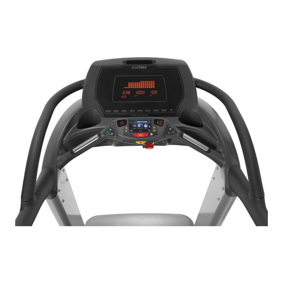
Screen
Hide thumbs
Also See for CardioTouch 770T:
- Service manual (261 pages) ,
- Owner's manual (106 pages) ,
- Owner's manual (88 pages)
Advertisement
Quick Links
Download this manual
See also:
Owner's Manual
Kit Number PKCP-23317
This instruction sheet describes how to install the CardioTouch screen for Cybex treadmill model
770T and 790T.
Tools Required
Phillips screwdriver
•
Flashlight
•
Clean cloth
•
Rubbing alcohol
•
ESD (Electrostatic Discharge) grounding strap.
•
Read and understand all instructions thoroughly before installing this kit.
Verify the kit contents shown.
1
Disconnect external power source
Unplug the treadmill from the power outlet.
WARNING: Shock and electrocution hazard
Unplug unit and let sit 10 minutes before cleaning or performing maintenance
•
Electrical charge can remain in unit after unplugging
•
Keep water and liquids away from electrical parts
•
NOTICE:
Component damage
Wear an ESD grounding strap during this procedure. Connect ESD grounding strap to
frame bolts or unpainted metal of frame. If ESD grounding strap is not available, touch
frame bolts or unpainted metal of frame before handling any electronics.
CardioTouch
2
3
Page 1 of 11
Screen 770T
®
Description
1
CardioTouch Screen
2
USB key FOB W-Lanyard
3
USB 2.0 flash drive
Installation Instructions
www.cybexintl.com
Advertisement

Subscribe to Our Youtube Channel
Related Manuals for CYBEX CardioTouch 770T


Summary of Contents for CYBEX CardioTouch 770T
- Page 1 CardioTouch Screen 770T ® Installation Instructions Kit Number PKCP-23317 This instruction sheet describes how to install the CardioTouch screen for Cybex treadmill model 770T and 790T. Tools Required Phillips screwdriver • Flashlight • Clean cloth • Rubbing alcohol • ESD (Electrostatic Discharge) grounding strap.
- Page 2 Remove headphone jack 1. Remove the two screws securing the headphone jack cover to the handset using a Phillips screwdriver. Description Connector J6 Headphone jack cable Headphone jack cover Screws (2) Handset 2. Unplug the headphone jack cable carefully from the connector J6 on the MCC board (connector on right).
- Page 3 2. Unplug cables by un-latching connector from the MCC board with the following procedure Use flashlight to locate connector latch and orientation. Note the orientation of the cable connector: A. Press in the latch of the cable connector. DO NOT PULL CONNECTOR OUT BY THE WIRES! Latch...
- Page 4 4. Lift the handset assembly carefully and unplug the graphics board cable (J12). The iPod cable is held in place by a notch in the access cover. A. Press in both side latches of the cable connector. DO NOT PULL CONNECTOR OUT BY THE WIRES! B.
- Page 5 3. Remove the two screws and USB cover from the two support brackets using a Phillips screwdriver. Description USB Cover Screws (2) Support Bracket 4. Remove the four screws and two support brackets using a Phillips screwdriver. Description Screws (2) Support Brackets Handset 5.
- Page 6 6. Remove the CardioTouch screen and clean the area with a clean cloth and rubbing alcohol. Description Clean this area Install CardioTouch screen 1. Place the CardioTouch board in place in the handset. Description Handset Screws (7) Ground cable CardioTouch board 2.
- Page 7 5. Install the four screws and two support brackets using a Phillips screwdriver. Description Screws (2) Support Brackets Handset 6. Install the USB cover to the two support brackets using two screws and a Phillips screwdriver. Description USB Cover Screws (2) Support Bracket 7.
- Page 8 Install handset assembly 1. Place the handset assembly in position and plug in the following cables: contact heart rate grips (J7), handset membrane (J9), graphics board (J12) and the ground wire. Note the orientation of the cable connectors. Description Graphics Board (J12) (under cover) Handset Membrane (J9) Contact Heart Rate Grips (J7) Ensure the iPod cable is routed through the notch in the access cover.
- Page 9 1. Plug USB stick into PC. 2. Delete any files on USB stick. Verify USB stick is blank. 3. Please go to the Team Cybex service product pages for the latest software files or contact Cybex Customer Service at 508-533-4300 to receive via email.
- Page 10 Install software through internal USB port 1. Remove the two screws securing the headphone jack cover to the handset using a Phillips screwdriver. Description Internal USB Port Headphone jack cover Screws (2) Handset 2. Insert USB stick into the internal USB port. Do NOT insert USB stick into optional E3 View Monitor.
- Page 11 Cybex® and the Cybex logo are registered trademarks of Cybex International, Inc. 10 Trotter Drive Medway, MA 02053 508-533-4300 • FAX 508-533-5183 • www.cybexintl.com Copyright © 2013, Cybex International, Inc. All rights reserved • LT-23328-4 C • October 2013 www.cybexintl.com Page 11 of 11...
Need help?
Do you have a question about the CardioTouch 770T and is the answer not in the manual?
Questions and answers