
Related Manuals for CYBEX 772A


Summary of Contents for CYBEX 772A
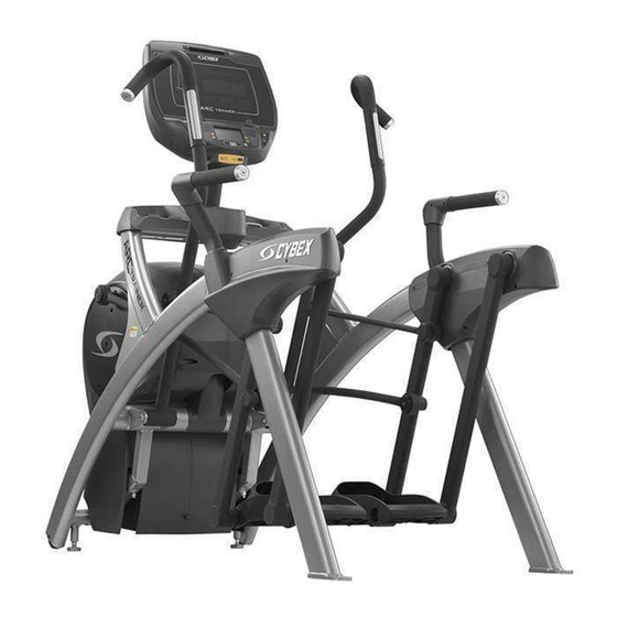
- Page 1 Cybex 772A/772AT Arc Trainer ® Cybex GO Monitor, Owner’s Manual Cardiovascular Systems Part Number 5772-4 A www.cybexintl.com...
-
Page 2: Table Of Contents
Apple. DISCLAIMER: Cybex International, Inc., makes no representations or warranties regarding the contents of this manual. We reserve the right to revise this document at any time or to make changes to the product described within it without notice or obligation to notify any person of such revisions or changes. -
Page 3: Fcc Compliance Information
Cybex Owner’s Manual FCC Compliance Information Changes or modifications to this unit not expressly approved by the party responsible for compliance could void the user’s authority to operate the equipment! This equipment has been tested and found to comply with the limits for a Class B digital device, pursuant to part 15 of the FCC Rules. -
Page 4: Safety
Cybex Owner’s Manual Safety Read all instructions and warnings before using. Ground and Voltage Information WARNING: Shock and electrocution hazard. Connect unit to a grounded outlet. • Do not use voltage adapter or extension cord. • Cybex is not responsible for injuries or damages as a result of cord or plug modification. Verify voltage requirements of unit match local voltage requirements. - Page 5 Do not attempt electrical or mechanical repairs. Seek qualified repair personnel when servicing. If • you live in the USA, contact Cybex Customer Service at 888-462-9239. If you live outside the USA, contact Cybex Customer Service at 508-533-4300. Use only Cybex supplied components to maintain/repair unit.
-
Page 6: Warning And Caution Decals
508-533-5183 or contact Cybex Customer Service at 888-462-9239. If you are located outside of the USA, call 508-533-4300. For location or part number of labels, see the parts list and exploded-view diagram on the Cybex web site at www.cybexintl.com. - Page 7 Cybex Owner’s Manual English - French - German - Spanish 4” W X 3“ H X .19” R English - Japanese - Russian 4” W X 3“ H X .19” R OTES: 1. WARNING FONT - ARIAL BOLD 18 BOLD.
-
Page 8: Label Placement
Cybex Owner’s Manual Label Placement 770A-331-4 Label, Warning, Access tray, Left 770A-331-E Label, Warning, Access tray, Left, Canadian 770A-332-4 Label, Warning, Access tray, Right 770A-332-E Label, Warning, Access tray, Right, Canadian DE000004-4 Decal, Caution Moving Parts DE-17155-4 Label, Warning, Hot flywheel... -
Page 9: Assembly
24” (61 cm) fixed length. Quick Start, five workout groups, seven workouts, four heart rate workouts, and two Workouts power workouts Upper console: Cybex GO Monitor. Console Displays Cal/Hr, Distance, Strides per Minute, Calories, Watt, MET, and BPM. Features Lower console: Two numeric displays for incline, time, resistance and level. -
Page 10: Specifications - 772At
24” (61 cm) fixed length. Quick Start, five workout groups, seven workouts, four heart rate workouts, and two Workouts power workouts Upper console: Cybex GO Monitor. Console Displays Cal/Hr, Distance, Strides per Minute, Calories, Watt, MET, and BPM. Features Lower console: Two numeric displays for incline, time, resistance and level. -
Page 11: Environment And Storage
Minimum clearance fo 12” (30 cm) between units for proper wireless heart rate signal operation. Electrical Power Requirements The Cybex GO Monitor is supplied with a power cord, The AC power kit is optional. Verify unit is connected to an outlet having the same configuration as the plug. -
Page 12: Assembly Procedure
Cybex Owner’s Manual Ensure outlets used by this product meet all local and federal building codes. • 772A Assembly Procedure Tools Required Phillips screwdriver • Stubby Phillips screwdriver • 3/16” Allen wrench (supplied) • 7/32” Allen wrench (supplied) • 9/16” Open end wrench (2) •... - Page 13 Cybex Owner’s Manual...
- Page 14 Cybex Owner’s Manual Verify contents of hardware pack See hardware pack listings and hardware pack contents. See Customer Service for contact information if any parts are missing. Item Description Part Number Quantity 7/32” Allen Wrench BK030204 BHSCS .375-16 x 2.50”...
- Page 15 Cybex Owner’s Manual...
- Page 16 4. Move unit to intended location. 5. Lower rear support legs. Install 772A console assembly. 1. Place the console into position on the frame. Do not pinch cables while lowering the console. Locknuts (4) Console...
- Page 17 Cybex Owner’s Manual Install coax cable and ethernet cables 1. Plug the coax cable connectors into each other and tighten threaded connector. Coax cable connectors Ethernet cable connectors 2. Plug the ethernet cable connectors into each other. Install accessory tray base Install the four screws using a stubby Phillips screwdriver.
- Page 18 Cybex Owner’s Manual Install accessory tray top Install the two screws using a stubby Phillips screwdriver. Accessory Tray Top Accessory Tray Base Screws (2) Install accessory tray bottom 1. Install the grommet to the frame. Frame Grommet...
- Page 19 Cybex Owner’s Manual 2. Install the accessory tray bottom to the accessory tray base with three screws using a Phillips screwdriver. Accessory Tray Bottom Accessory Tray Base Screw Screws (2) Install handrails. 1. Remove three locknuts from the left support leg using two 9/16” open end wrenches. Keep the two spacers in place.
- Page 20 Cybex Owner’s Manual 3. Install the left inner rear cover with two screws using a Phillips screwdriver. Left Inner Rear Cover Screws (2) 4. Install the left outer rear cover with five screws using a Phillips screwdriver. Screws (2) Left Outer...
- Page 21 Cybex Owner’s Manual 6. Loosen the two screws in the right inner and outer collars using a Phillips screwdriver. Description Screws (2) Inner Collar Outer Collar Cover 7. Slide the inner and outer collars onto the right covers. 8. Insert the tabs of the collars into the slots of the cover.
- Page 22 Cybex Owner’s Manual 13. Install the right inner rear cover with two screws using a Phillips screwdriver. Right Inner Rear Cover Screws (2) 14. Install the right outer rear cover with five screws using a Phillips screwdriver. Screws (2) Right Outer Rear Cover Screws (3) 15. Install the right top rear cover with five screws using a Phillips screwdriver.
- Page 23 Cybex Owner’s Manual Install foot pads Have one person lift the unit while a second person places a foot pad under each of the two back feet. Foot Pads (2) Level unit Confirm unit is on a level surface. If not, use a 9/16” open-end wrench to adjust the leveling feet up or down.
- Page 24 Cybex Owner’s Manual 2. Insert the ethernet coupler into the mounting plate by hooking the lower tab into the mounting plate and snapping in the upper tab. Item Description Upper tab Mounting plate Ethernet coupler Lower tab Installed Front of unit 3. Install 7’...
-
Page 25: 772At Assembly Procedure
Cybex Owner’s Manual 772AT Assembly Procedure Tools Required Phillips screwdriver • Stubby Phillips screwdriver • 3/16” Allen wrench (supplied) • 7/32” Allen wrench (2) (supplied) • 9/16” Open end wrench (2) • The words “left” and “right” denote the user’s orientation. - Page 26 Cybex Owner’s Manual...
- Page 27 Cybex Owner’s Manual Verify contents of hardware pack See hardware pack listings and hardware pack contents. See Customer Service for contact information if any parts are missing. Item Description Part Number Quantity Flange Spacer 600A-311 3/16” Allen Wrench BK030201 7/32” Allen Wrench BK030204 BHSCS .375-16 x 2.25”...
- Page 28 Cybex Owner’s Manual...
- Page 29 Cybex Owner’s Manual Lift and move unit 1. Remove large bolts and shipping supports. Keep package material on linkage arms at this time. This will protect the paint from scratching during assembly. 2. Grasp each rear support leg firmly and lift with one person on each side.
- Page 30 Cybex Owner’s Manual Install coax cable and ethernet cables 1. Plug the coax cable connectors into each other and tighten threaded connector. Coax cable connectors Ethernet cable connectors 2. Plug the ethernet cable connectors into each other. Install accessory tray base Install the four screws using a Phillips screwdriver.
- Page 31 Cybex Owner’s Manual Install accessory tray top Install the two screws using a Phillips screwdriver. Accessory Tray Top Accessory Tray Base Screws (2) Install accessory tray bottom 1. Install the grommet to the frame. Frame Grommet...
- Page 32 Cybex Owner’s Manual 2. Install the accessory tray bottom to the accessory tray base with three screws using a Phillips screwdriver. Accessory Tray Bottom Accessory Tray Base Screw Screws (2) Install handrails. 1. Remove three locknuts from the left support leg using two 9/16” open end wrenches. Keep the two spacers in place.
- Page 33 Cybex Owner’s Manual 3. Install the left inner rear cover with two screws using a Phillips screwdriver. Left Inner Rear Cover Screws (2) 4. Install the left outer rear cover with five screws using a Phillips screwdriver. Screws (2) Left Outer...
- Page 34 Cybex Owner’s Manual 6. Loosen the two screws in the right inner and outer collars using a Phillips screwdriver. Description Screws (2) Inner Collar Outer Collar Cover 7. Slide the inner and outer collars onto the right covers. 8. Insert the tabs of the collars into the slots of the cover.
- Page 35 Cybex Owner’s Manual 13. Install the right inner rear cover with two screws using a Phillips screwdriver. Right Inner Rear Cover Screws (2) 14. Install the right outer rear cover with five screws using a Phillips screwdriver. Screws (3) Right Outer Rear Cover Screws (3) 15. Install the right top rear cover with five screws using a Phillips screwdriver.
- Page 36 Cybex Owner’s Manual Remove left and right handle assembly The left and right handle assemblies are shipped in rotated positions. The handle assemblies must be removed and rotated 180 degrees for proper setup and assembly. Shipping Position 1. Remove a screw and washer from the left handle assembly using two 7/32” Allen wrenches.
- Page 37 Cybex Owner’s Manual 7. Remove a screw and washer from the right handle assembly using two 7/32” Allen wrenches. Screw Washer Right Handle Pivot Pin Assembly 8. Slide pivot pin assembly out and remove right handle assembly. 9. Rotate right handle assembly 180 degrees.
- Page 38 Cybex Owner’s Manual Install right linkage rod 1. Pivot right handle assembly up and slide right linkage rod onto right arm. Linkage Rod Flange Right Linkage Spacer Washer Loctite Screw Right Arm 2. Place a drop of Loctite onto the screw.
- Page 39 Cybex Owner’s Manual Connect contact heart rate cable 1. Plug right heart rate cable into main frame socket. Right Side Main Frame Shown Socket Heart Rate Wire Position plug so handle does not rub cable during operation. 2. Plug left heart rate cable into main frame socket.
- Page 40 Cybex Owner’s Manual Level unit Confirm unit is on a level surface. If not, use a 9/16” open-end wrench to adjust the leveling feet up or down. Leveling Feet Install coax and ethernet cables 1. Install 6’ coax cable to the coax cable connector in base of unit.
-
Page 41: Cybex Go Setup
Netpulse Gateway installed and running, providing the connection via: • Wired (Ethernet) – Ethernet cable is connected to the Cybex equipment through a network switch to the Gateway. Wireless – Gateway has been installed in the facility using a unique wireless access point. - Page 42 Cybex Owner’s Manual Cybex GO installer The Cybex GO installer only occurs during the initial installation of the unit. Once complete, refer to Initial setup. 1. Tap “NEXT” to begin configuration. Description NEXT 2. Select one of the three network devices.
- Page 43 Cybex Owner’s Manual Wireless network interface 1. Tap Wireless network interface. 2. Tap NEXT to confirm selection. 1. Tap TEST CONNECTION. This may take up to five minutes to complete. If test fails, retry. Description TEST CONNECTION 2. Tap NEXT after test passes and displays “Connected!”.
- Page 44 Cybex Owner’s Manual TV only 1. Tap TV only. No network connection. 2. Select Default Country. 3. Tap OK 4. Set Date and Time. 5. Tap NEXT. 6. Go to Channel configuration.
- Page 45 1. Select Analog/Digital Cable and tap NEXT. This will scan for all available channels. The scan can take 20 minutes to complete. If scan was previously configured and stored, choose Download Configuration and tap NEXT to configure other units. Go to Test Cybex GO Monitor. Description Analog/Digital Cable...
- Page 46 Cybex Owner’s Manual 2. Tap SAVE CONFIGURATION TO SERVER. Description SAVE CONFIGURATION TO SERVER To configure each of the channels see Channel configuration. 3. Tap FINISH to complete installation. Cybex GO monitor will reset. Do not call Netpulse.
- Page 47 The channel configuration only needs to be performed on the first unit installed. Configure the first unit completely, save the configuration, then assemble and configure all other units. Test Cybex GO monitor Test Cybex GO monitor by tapping CONTINUE AS GUEST at home screen. Select from TV or Videos to test Cybex GO monitor...
-
Page 48: Equipment Setup
Equipment Setup Units setup Initial setup only occurs during the installation of the unit. Once complete, refer to Setup Options. CYBEX Press and hold Cybex logo for 6 seconds to access Screen LOGO Lock and Toolbox. See Preventive Maintenance section. LANGUAGE... - Page 49 Cybex Owner’s Manual Setup options Enter setup options. CYBEX Press and hold Cybex logo for 6 seconds to access Screen LOGO Lock and Toolbox. See Preventive Maintenance section. LANGUAGE Press and hold language logo for 6 seconds to access ENGLISH ICON Screen Lock and Toolbox.
-
Page 50: Testing Operation
Cybex Owner’s Manual Testing Operation Use the following instructions to test the full resistance and incline range of the unit: 1. Plug the optional power cord into a power outlet from a grounded circuit, See Electrical Requirements. Coil up the remainder of the power cord and place it out of the way. If you do not have the optional power supply, skip to step 3. -
Page 51: Operation
Cybex Owner’s Manual Operation Intended Use The intended commercial use of this machine is to aid exercise and improve general physical fitness. Terms Used Active Mode – Any time the unit is controlling resistance and accumulating workout data. Active Mode begins after tapping QUICK START icon during the initial count-down screen, after completing the setup for a workout, or by default if the initial count-down screen times out and enters Quick Start mode. -
Page 52: User Control Symbols Used
RESISTANCE UP Adjust Resistance up. RESISTANCE DOWN Adjust Resistance down. VOLUME UP Adjust Volume up. VOLUME DOWN Adjust Volume down. Cybex GO - Channel UP CHANNEL/TRACK CONTROL iPod/iPhone/iPad - NEXT track (option) CHANNEL/TRACK Cybex GO - Channel DOWN CONTROL iPod/iPhone/iPad - PREVIOUS track (option) -
Page 53: Cardiotouch Symbols Used
Cybex Owner’s Manual CardioTouch Symbols Used Icon Icon Name Description QUICK Quick Start enters Active Mode at the default incline and resistance with time counting up from 0:00. START WORKOUTS Tap Workouts icon to enter workout group selection. iPOD Tap iPod icon to enter iPod control menu. If iPod is not connected, icon will be grayed out. - Page 54 Select to provide more information and details. SCALE Displays current value and high/low range. CYBEX LOGO Press and hold Cybex logo for 6 seconds to access Screen Lock and Toolbox. See Preventive Maintenance section. LANGUAGE Tap language icon to select available languages. Set...
-
Page 55: Cardiotouch Screen And User Controls
Cybex Owner’s Manual CardioTouch Screen and User Controls Incline Incline CardioTouch Resistance Resistance Keys Display Screen Display Keys Volume STOP Key Fan Key Channel/Track Keys Keys Displays — Incline and Resistance are shown in the LED displays. Keys — User controls for Incline, Resistance, Volume, STOP, Fan and Channel/Track. -
Page 56: Cybex Go Console And User Controls
Cybex Owner’s Manual Cybex GO Console and User Controls Cybex GO Console Data bar Displays messages and workout data. Video display area Displays video, data, or blank. Menu bar Menu icons for Cybex GO options. Heart rate indicator Display heart rate and multi color indicator. -
Page 57: Cybex Go Console Log In Or Sign Up
Sign up as a new user or login with existing account. History Review workout history if logged in. Cybex GO Console Log In or Sign Up XID is a universal network that allows you to log into connected fitness equipment. An XID account allows you to: Create playlists for your favorite audio and video tracks •... -
Page 58: Mount And Dismount
Cybex Owner’s Manual Mount and Dismount WARNING: Moving parts and fall hazard. To avoid serious injury wait until foot plates come to a complete stop before getting off unit. 1. Verify unit is off or in Dormant Mode and foot plates are completely stopped. - Page 59 Cybex Owner’s Manual Intensity High High High Resistance Incline...
-
Page 60: Quick Operation Guide
Detailed Operation Guide Maximum user weight is 400 lbs. (181 kg). 1. Plug the optional power cord and Cybex GO Monitor power cord (Cybex GO Monitor units only) into a power outlet from a grounded circuit, See Electrical Requirements. Coil up the remainder of the power cord and place it out of the way. - Page 61 Cybex Owner’s Manual To select a workout, tap one of the workout icons from the workouts screen. Upon entering a workout the display will guide you through the appropriate settings. This is referred to as Workout Setup Mode. If the Start key is pressed now, all defaults for that workout will be accepted.
-
Page 62: Workout Selection
Workout Review is displayed for the preset time or until you press the Home key. The unit returns to Dormant Mode when using the optional AC adapter. Workout Selection With the 772A and 772AT you may choose from Quick Start or Workouts. Speed is never predetermined. Change speed by changing stride. Quick Start Press Quick Start. -
Page 63: Data Readouts
Cybex Owner’s Manual Data Readouts As the user exercises, the unit keeps track of and displays the following data: BPM (Beats Per Minute) – User’s current heart rate. Heart rate will appear when a signal is introduced. Calories – The total accumulated calories burned during workout. -
Page 64: Fan Control
Cybex Owner’s Manual Once the actual heart rate is determined, the LED to the right of the Data Readouts is blinking to the displayed BPM and the Heart LED lights up. The color of the light represents a scale of low to high target heart rate. -
Page 65: Maintenance
Maintenance All preventive maintenance activities must be performed on a regular basis. Performing routine preventive maintenance actions can aid in providing safe, trouble-free operation of all Cybex Strength Systems equipment. Cybex is not responsible for performing regular inspection and maintenance actions for your machines. -
Page 66: Cleaning Unit
Cybex is not responsible for performing regular inspection and maintenance actions for your unit. Instruct all personnel in equipment inspection and maintenance actions and also in accident reporting/ recording. -
Page 67: Remove Access Cover
Cybex Owner’s Manual Remove Access Cover 1. Remove the two lower screws securing the access cover using a Phillips screwdriver. Upper Screws (2) Access Cover Lower Screws (2) 2. Remove two upper screws securing the access cover using a Phillips screwdriver. Refer to the above diagram. -
Page 68: Drive Belts
Cybex Owner’s Manual Drive Belts There are two drive belts that may become loose, worn or cracked. Unless the belts have been removed and not replaced properly, it is unlikely the belts will come loose or need to be re-tensioned. -
Page 69: Cybex Go Monitor
Cybex Owner’s Manual Cybex GO Monitor Cleaning 1. Unplug the power cord from the wall socket. 2. Dust off the panel with a soft dry cloth as needed. The screen can be cleaned with computer screen wipes or other non-abrasive, moist, disposable wipes. -
Page 70: Recommended Service Schedule
This is the minimum recommended service. Determine distance. CYBEX Press and hold Cybex logo for 6 seconds to access Screen LOGO Lock and Toolbox. See Preventive Maintenance section. LANGUAGE Press and hold language logo for 6 seconds to access... -
Page 71: Statistics
Statistics The Statistics screen allows tracking of equipment usage. CYBEX Press and hold Cybex logo for 6 seconds to access Screen LOGO Lock and Toolbox. See Preventive Maintenance section. LANGUAGE Press and hold language logo for 6 seconds to access... -
Page 72: Customer Service
To speak with a customer service representative, call 888-462-9239 (for customers living within the USA) or 508-533-4300 (for customers outside the USA). The following information located on the serial number decal will assist our Cybex representatives in serving you. Unit Serial Number, Product Name and Model Number •... -
Page 73: Return Material Authorization (Rma)
Provide the model and serial number of your Cybex equipment. At Cybex’s discretion, the technician may request that you return the problem part(s) to Cybex for evaluation and repair or replacement. The technician will assign you a RMA number and will send you an ARS label. -
Page 74: Appendix - Workout Overviews
Cybex Owner’s Manual Appendix - Workout Overviews Weight Loss - Hill Climb A gentle calorie burner with steady work increases over 3 minutes followed by a 1 minute rest. Time 1:00 1:00 1:00 1:00 Level Warm Up Core Cool Down... -
Page 75: Weight Loss - Speed Bump
Cybex Owner’s Manual Weight Loss - Speed Bump A relatively steady workload includes a high output bump for increased energy expenditure. Time 1:00 1:00 1:00 1:00 1:00 1:00 Level Warm Up Core Cool Down Resistance Incline Target Pace Resistance Incline... -
Page 76: Strength - High Low
Cybex Owner’s Manual Strength - High Low Two levels of intensity and duration help develop muscular strength and endurance. Time 1:00 1:00 1:00 1:00 1:00 1:00 1:00 Level Warm Up Core Cool Down Resistance Incline Target Pace Resistance Incline Target Pace... -
Page 77: Strength - Bursts
Cybex Owner’s Manual Strength - Bursts Brief high-intensity segments are mixed with longer and easier intervals developing strength and aerobic capacity. Time 1:00 1:00 1:00 1:00 1:00 1:00 Level Warm Up Core Cool Down Resistance Incline Target Pace Resistance Incline... -
Page 78: Strength - Interval
Cybex Owner’s Manual Strength - Interval A repeating 15 second high intensity spike promotes strength gains Time 1:00 1:00 1:00 1:00 Level Warm Up Core Cool Down Resistance Incline Target Pace Resistance Incline Target Pace Resistance Incline Target Pace Resistance... -
Page 79: Fitness (Mens) , Shaping (Womens) - Total Leg
Cybex Owner’s Manual Fitness (Mens) , Shaping (Womens) - Total Leg Alternating levels of resistance and incline change the targeted muscle group in an interval format. Time 1:00 1:00 1:00 1:00 Level Warm Up Core Cool Down Resistance Incline Target Pace... -
Page 80: Fitness (Mens) - Target: Hip, Shaping (Womens) - Glute Camp
Cybex Owner’s Manual Fitness (Mens) - Target: Hip, Shaping (Womens) - Glute Camp 2 minutes of progressive resistance and incline targeting the hip extensors are followed by a 1 minute rest. Time 1:00 1:00 1:00 1:00 Level Warm Up Core... -
Page 81: Cardio - Hill Interval
Cybex Owner’s Manual Cardio - Hill Interval Moderate duration intervals with changes in incline and resistance promote cardio endurance with enough rest to repeat the process. Time 2:00 2:00 Level Warm Up Core Cool Down Resistance Incline Target Pace Resistance... -
Page 82: Cardio - Wave
Cybex Owner’s Manual Cardio - Wave A long duration interval promotes cardio endurance with enough rest to repeat the process. Time 1:00 1:00 1:00 1:00 Level Warm Up Core Cool Down Resistance Incline Target Pace Resistance Incline Target Pace Resistance... -
Page 83: Cardio - Interval
Cybex Owner’s Manual Cardio - Interval A 30 second charge improves aerobic power with 1 minute of recovery before a repeat. Time 1:00 1:00 1:00 Level Warm Up Core Cool Down Resistance Incline Target Pace Resistance Incline Target Pace Resistance... -
Page 84: Cardio - Heart Rate Control
Cybex Owner’s Manual Cardio - Heart Rate Control Requires HR transmitter. The Arc will adapt the resistance as you maintain speed to keep your heart rate at a certain level. Power - Constant Power You set the power in watts. Pedaling faster feels easier, pedaling slower feels harder; but the workload remains the same. - Page 86 10 Trotter Drive Medway, MA 02053 www.cybexintl.com 508-533-4300 FAX 508-533-5183 • •...
Need help?
Do you have a question about the 772A and is the answer not in the manual?
Questions and answers