Table of Contents
Advertisement
®
Thermalert
4.0 Series
Smart Integrated Infrared Sensors
Users Manual
PN 4968276, English, Rev. 1.1, May 2018
© 2018 Fluke Process Instruments. All rights reserved. Printed in Germany. Specifications subject to change without notice.
All product names are trademarks of their respective companies.
1.800.561.8187
information@itm.com
www.
.com
Advertisement
Table of Contents

Related Manuals for Fluke Thermalert 4.0


Summary of Contents for Fluke Thermalert 4.0
-
Page 1: Table Of Contents
Smart Integrated Infrared Sensors Users Manual PN 4968276, English, Rev. 1.1, May 2018 © 2018 Fluke Process Instruments. All rights reserved. Printed in Germany. Specifications subject to change without notice. All product names are trademarks of their respective companies. 1.800.561.8187 information@itm.com... - Page 2 Warranty The manufacturer warrants this instrument to be free from defects in material and workmanship under normal use and service for the period of two years from date of purchase. This warranty extends only to the original purchaser. This warranty shall not apply to fuses, batteries or any product which has been subject to misuse, neglect, accident, or abnormal conditions of operation.
-
Page 3: Table Of Contents
Table of Contents Chapter Page ..............................3 ABLE OF ONTENTS ............................... 7 IST OF ABLES ..............................8 IST OF IGURES ............................10 OMPLIANCE TATEMENT ............................. 11 AFETY NFORMATION ................................15 ONTACTS ............................... 16 ESCRIPTION ..............................18 ECHNICAL 2.1 Measurement Specification ..................................... 18 2.2 Optical Specifications ...................................... - Page 4 5.4.5 Alarm Output AL ....................................35 5.5 Model 6-Wire ........................................36 5.5.1 Back Panel......................................36 5.5.2 Cable Connection ....................................36 5.5.3 Terminal Strip ......................................36 5.5.4 Analog Out ......................................36 5.5.4.1 mA Output ....................................... 36 5.5.4.2 V Output ......................................37 5.5.4.3 TC Output ......................................
-
Page 5: List Of Tables
..............................50 CCESSORIES 8.1 Electrical Accessories ..................................... 50 8.1.1 High Temp Cable 12-Wire (A-CB-HT-M16-W12-xx) ..........................51 8.1.2 Low Temp Cable 12-Wire (A-CB-LT-M16-W12-xx)..........................53 8.1.3 Terminal Block (A-T40-TB) ..................................55 8.1.4 Terminal Block with Enclosure (A-T40-TB-ENC) ..........................56 8.1.5 Power Supply DIN Rail (A-PS-DIN-24V) ............................... 57 8.1.6 Power Supply with Terminal Box (A-PS-ENC-24V) .......................... -
Page 6: List Of Figures
10.5 Sensor Control ......................................81 10.5.1 Analog Output ...................................... 81 10.5.2 Relay Output ......................................81 10.6 RS485 Communication ....................................81 10.7 Multidrop Mode ......................................81 10.8 Command List ....................................... 83 11 A ................................87 PPENDIX 11.1 Optical Diagrams ......................................87 11.1.1 LT-07 Models ....................................... - Page 7 List of Tables Table Page Table 5-1: Terminal Connections ......................... 30 Table 5-2: Power Supply Requirements for Multiple Loads ................. 34 Table 5-3: Pin Assignment for Terminal Strip ....................... 36 Table 5-4: Pin Assignment for DIN Connector ..................... 38 Table 5-5: Ratio between Analog Input Voltage and Emissivity ................38 Table 8-6: Available Cable Lengths ........................
- Page 8 List of Figures Figure Page Figure 1-1: Available Models ..........................17 Figure 2-1: Dimensions for the 2-Wire and 6-Wire Model ..................23 Figure 2-2: Dimensions for the 12-Wire Model ..................... 23 Figure 4-1: One Earth Ground at the Sensor (left) or at the Power Supply (right)..........26 Figure 4-2: Principle of the Galvanic Isolation for the 6-Wire Model ..............
- Page 9 Figure 8-4: Terminal Block in an Enclosure ......................56 Figure 8-5: Industrial Power Supply ........................57 Figure 8-6: Power Supply with Terminal Box ....................... 58 Figure 8-7: USB/RS485 Converter ........................59 Figure 8-8: Overview to Mechanical Accessories....................60 Figure 8-9: Mounting Nut ............................. 61 Figure 8-10: Fixed Bracket ...........................
-
Page 10: Compliance Statement
Compliance Statement The device complies with the requirements of the European Directives: EC – Directive 2014/30/EU – EMC EC – Directive 2011/65/EU – RoHS II EN 61326-1: 2013 Electrical measurement, control and laboratory devices - Electromagnetic susceptibility (EMC) EN 50581: 2012 Technical documentation for the evaluation of electrical products with respect to restriction of hazardous substances (RoHS) Electromagnetic Compatibility Applies to use in Korea only. -
Page 11: Safety Information
Safety Information This document contains important information, which should be kept at all times with the instrument during its operational life. Other users of this instrument should be given these instructions with the instrument. Eventual updates to this information must be added to the original document. The instrument can only be operated by trained personnel in accordance with these instructions and local safety regulations. - Page 12 Safety Symbol Description Read all safety information before in the handbook Hazardous voltage. Risk of electrical shock. Warning. Risk of danger. Important information. See manual. Laser warning Earth (ground) terminal Protective conductor terminal Switch or relay contact DC power supply Conforms to European Union directive.
-
Page 13: Contacts
To prevent possible electrical shock, fire, or personal injury follow these guidelines: • Read all safety information before you use the product. • Use the product only as specified, or the protection supplied by the product can be compromised. • Do not use the product around explosive gases, vapor, or in damp or wet environments. •... -
Page 14: Description
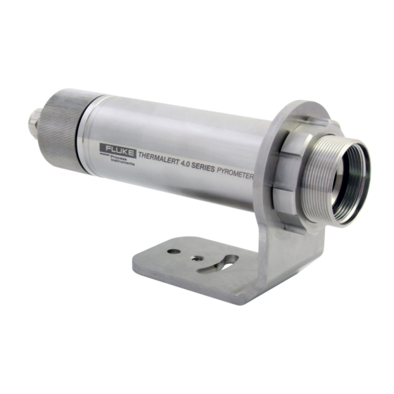
Users Manual, Rev. 1.1, May 2018 1 Description The Thermalert 4.0 sensor is an infrared thermometer that differs in spectral responses to be capable of covering a broad range of applications such as metal, glass, and plastics. The Thermalert 4.0 Series introduces improved temperature measurement specifications, an extended operating ambient temperature range, multiple user interfaces and various network communications. -
Page 15: Figure 1-1: Available Models
Description Measurement Specification Figure 1-1: Available Models 2-Wire 6-Wire 4 to 20 mA, Alarm, USB Analog Out, RS485, USB 12-Wire Analog In/Out, Alarm, Trigger, RS485, USB 1.800.561.8187 information@itm.com www. .com... -
Page 16: Technical Data
® Thermalert 4.0 Series Users Manual, Rev. 1.1, May 2018 2 Technical Data 2.1 Measurement Specification Temperature Range LT-07 -20 to 600°C (-4 to 1112°F) LT-15 -20 to 600°C (-4 to 1112°F) LT-30 -20 to 600°C (-4 to 1112°F) LT-50 -40 to 1000°C (-40 to 1832°F) LT-70 -40 to 1000°C (-40 to 1832°F) - Page 17 Technical Data Measurement Specification G5-70 60 ms MT-30 130 ms MT-70 130 ms P3-20 130 ms HT-60 130 ms System Accuracy ± (3°C + 1% of reading) for T > 75°C (167°F) meas All other ± 1% of reading or ± 1.0°C (2.0°F) for T >...
-
Page 18: Optical Specifications
® Thermalert 4.0 Series Users Manual, Rev. 1.1, May 2018 2.2 Optical Specifications Optical Resolution Focus Distances LT-07 CF0 (plastic lens) LT-15 15:1 SF0 (plastic lens) LT-30 33:1 SF0, CF1, CF2 LT-50 50:1 SF0, CF2 LT-70 70:1 SF2, CF2 P7-30 33:1 G7-70 70:1... -
Page 19: Electrical Specifications
Technical Data Electrical Specifications 2.3 Electrical Specifications 2.3.1 Model 2-Wire Power 12 to 24 VDC Outputs 4 to 20 mA, loop impedance max. 500 Ω Analog Alarm 24 V / 150 mA Digital USB: version 2.0, micro-B connector (only for the setup of the instrument) 2.3.2 Model 6-Wire Power + 24 VDC nominal (20 to 48 VDC), 100 mA @ 24 V... -
Page 20: Environmental Specifications
® Thermalert 4.0 Series Users Manual, Rev. 1.1, May 2018 2.4 Environmental Specifications Ingress Protection IP65 / IEC 60529 (NEMA-4) Operating temperature -20 to 85°C (-4 to 185°F) without cooling 10 to 120°C (50 to 250°F) with air cooling 10 to 175°C (50 to 350°F) with water cooling 10 to 315°C (50 to 600°F) water cooled by ThermoJacket Storage temperature -20 to 85°C (-4 to 185°F) -
Page 21: Dimensions
Technical Data Dimensions 2.5 Dimensions 2.5.1 Model 2-Wire / 6-Wire Figure 2-1: Dimensions for the 2-Wire and 6-Wire Model 2.5.2 Model 12-Wire Figure 2-2: Dimensions for the 12-Wire Model 1.800.561.8187 information@itm.com www. .com... -
Page 22: Scope Of Delivery
® Thermalert 4.0 Series Users Manual, Rev. 1.1, May 2018 2.6 Scope of Delivery The scope of delivery includes the following: • Sensor • Mounting nut • Fixed bracket • USB cable (only for the setup of the instrument) • Operator's manual (as pdf file on data carrier) •... -
Page 23: Basics
Basics Measurement of Infrared Temperature 3 Basics 3.1 Measurement of Infrared Temperature All surfaces emit infrared radiation. The intensity of this infrared radiation changes according to the temperature of the object. Depending on the material and surface properties, the emitted radiation lies in a wavelength spectrum of approximately 1 to 20 µm. -
Page 24: Environment
® Thermalert 4.0 Series Users Manual, Rev. 1.1, May 2018 4 Environment 4.1 Ambient Temperature The sensor is suited for a maximal operating temperature, see section 2.4 Environmental Specifications, page 22. The operating temperature can be extended by using the air/water-cooled housing accessory, see section 8.2.10 Air/Water-Cooled Housing, page 71. -
Page 25: Figure 4-2: Principle Of The Galvanic Isolation For The 6-Wire Model
Environment Electrical Interference Figure 4-2: Principle of the Galvanic Isolation for the 6-Wire Model Isolation + VDC + Analog Out AGND Isolation RS485-A RS485-B Housing Shield Figure 4-3: Principle of the Galvanic Isolation for the 12-Wire Model Isolation + VDC (M) GND (L) Trigger (F) + Analog Out (J) -
Page 26: Installation
® Thermalert 4.0 Series Users Manual, Rev. 1.1, May 2018 5 Installation Risk of Personal Injury When this instrument is being used in a critical process that could cause property damage and personal injury, the user should provide a redundant device or system that will initiate a safe process shutdown in the event that this instrument should fail. -
Page 27: Viewing Angles
Installation Viewing Angles 5.3 Viewing Angles The sensor head can be placed at any angle from the target less than 45°. Figure 5-2: Acceptable Sensor Viewing Angles Best perpendicular to target Acceptable Angles Good up to 45° to target 45° to 90° to target 5.4 Model 2-Wire The 2-wire model provides a standard two-wire current loop output and USB communications. -
Page 28: Cable Connection
® Thermalert 4.0 Series Users Manual, Rev. 1.1, May 2018 equivalent to an emissivity value of 1.00. The appendix lists typical emissivity values for common materials, see section 11.3 Typical Emissivity Values, page 96. Table 5-1: Terminal Connections Designation Description alarm output ... - Page 29 Installation Model 2-Wire Step 3 The cable gland consists of a PG nut (1), a relief bushing (2) and a metal cone ring (3). Step 4 Put the following on the cable: the PG nut (1) and the relief bushing (2). Step 5 Prepare the cable.
- Page 30 ® Thermalert 4.0 Series Users Manual, Rev. 1.1, May 2018 Step 7 Make sure to have a proper contact between the braided shield and the metal cone ring. Step 8 Place the PG screwed cable gland back into the outer cap. Tighten the PG nut firmly.
-
Page 31: Ma Single Loop
5.4.3 mA Single Loop The 2-wire model of the Thermalert 4.0 Series is an infrared thermometer with a built-in two-wire transmitter. Power it up with an appropriate direct current source and you get a 4 to 20 mA current. The current varies with target temperature over the full temperature span of the instrument. -
Page 32: Table 5-2: Power Supply Requirements For Multiple Loads
® Thermalert 4.0 Series Users Manual, Rev. 1.1, May 2018 Figure 5-5: Equivalent Circuit Diagram: Infrared Sensor with Multiple Loads Loop Wires Controller Indicator Infrared Sensor Sensor min. 12 V max. 24 V Supply Assume the resistances are as follows: ��... -
Page 33: Ma Multiple Loops
Installation Model 2-Wire 5.4.4 mA Multiple Loops The following figure is an example of a multiple loop system. Two loops are operated from a single power supply. An arrangement of this type is suitable for measuring temperatures at two or more stations with an independent readout for each station. -
Page 34: Model 6-Wire
5.5.4 Analog Out The 6-wire model of the Thermalert 4.0 Series is an infrared thermometer with a built-in analog output to drive analog devices. The output can be configured to output mA, V, or TC by means of software or a dedicated ASCII command. -
Page 35: Output
Installation Model 12-Wire Figure 5-9: Wiring Analog Out as Current Output A specific feature for the testing or calibrating of connected equipment allows the current loop output to bet set to specific values, under range or over range using a dedicated ASCII command. Via such functionality, you can force the instrument, operating in the 4-20 mA mode, to transmit an output current less than 4 mA (e.g. -
Page 36: Rs485 Communication
® Thermalert 4.0 Series Users Manual, Rev. 1.1, May 2018 Table 5-4: Pin Assignment for DIN Connector Description RS485-A RS485-B FTC1 (emissivity setting) FTC2 (background temperature compensation) Shield Trigger– with GND Relay contact (alarm) Relay contact (alarm) + Analog out (positive) AGND (analog ground) GND (digital ground) + VDC power supply... -
Page 37: Figure 5-13: Principle Of Background Temperature Compensation
Installation Model 12-Wire temperature is significantly hotter than the target temperature. For instance, the higher temperature of a furnace wall could lead to hotter temperatures being measured, especially for low emissivity targets. Background temperature compensation allows for the impact of reflected radiation in accordance with the reflective behavior of the target. -
Page 38: Trigger Input
® Thermalert 4.0 Series Users Manual, Rev. 1.1, May 2018 Figure 5-14: Adjustment of Background Temperature Compensation at FTC2 Input (Example) Sensor FTC2 (D) 0 to 10 VDC AGND (K) 5.6.5 Trigger Input The trigger input can be used either as Reset or Hold, or as Laser switch. The trigger function is activated by shorting the external input to digital ground (pin GND). -
Page 39: Laser
5.6.7 Analog Out The 12-wire model of the Thermalert 4.0 Series is an infrared thermometer with a built-in analog output to drive analog devices. The output can be configured to output mA or V by means of software or a dedicated ASCII command. -
Page 40: Output
® Thermalert 4.0 Series Users Manual, Rev. 1.1, May 2018 Figure 5-19: Wiring Analog Out as Current Output Sensor + AO (J) AGND (K) GND (L) +VDC (M) A specific feature for the testing or calibrating of connected equipment allows the current loop output to be set to specific values, under range or over range using a dedicated ASCII command. -
Page 41: Rs485
Converter, page 59. The RS485 interface allows communication either via the standard Software or directly via dedicated ASCII commands, see section 10 Programming Guide, page 78. 6.1 Specification Technical Data for Thermalert 4.0 Sensor: Physical layer: RS485, 2-wire, half-duplex, electrically isolated Baud rate: 4800, 9600, 19200, 38400, 57600, 115200 Bit/s... -
Page 42: Wiring
When the converter is connected, the computer gets one virtual COM port. Note In serial RS485 communication, the Thermalert 4.0 sensors support the 2-wire / half duplex mode only! 1.800.561.8187 information@itm.com www. -
Page 43: Multiple Sensors
6.3.4 Multiple Sensors For an installation of two or more Thermalert 4.0 sensors in a RS485 network (2-wire, half duplex), each sensor needs its specific RS485 network address (1 - 32). Once all the units are addressed, wire up the units in the 2-wire multidrop manner, whereas all A and B signals must be connected to common lines. -
Page 44: Operation
® Thermalert 4.0 Series Users Manual, Rev. 1.1, May 2018 7 Operation 7.1 Laser The laser sighting allows fast and precise aiming at small, rapidly moving targets, or targets passing at irregular intervals. The laser is specially aligned with the sensor’s lens to provide accurate, non-parallax pinpointing of targets. -
Page 45: Peak Hold
Operation Post Processing Figure 7-2: Averaging Temp Output temperature Object temperature Temperature jump 90% of temperature jump Average Time Time A low-level input (GND) at external trigger input will promptly interrupt the averaging and start the calculation again. For sensors without an external trigger input (2- and 6-wire models) the dedicated ASCII command should be used. -
Page 46: Advanced Peak Hold
® Thermalert 4.0 Series Users Manual, Rev. 1.1, May 2018 and the output will resume tracking the object temperature until a new valley is reached. The range for the hold time is 0.1 to 998.9 s Figure 7-4: Valley Hold Temp Output temperature Object temperature... -
Page 47: Advanced Valley Hold
Operation Post Processing 7.2.5 Advanced Valley Hold This function works like the advanced peak hold function, except that it will search the signal for a local minimum. 7.2.6 Advanced Peak Hold with Averaging The output signal delivered by the advanced peak hold functions tends to jump up and down. This is due to the fact that only maximum points of the otherwise homogenous trace will be shown. -
Page 48: Accessories
® Thermalert 4.0 Series Users Manual, Rev. 1.1, May 2018 8 Accessories 8.1 Electrical Accessories The following electrical accessories are available: • High Temp Cable 12-Wire (A-CB-HT-M16-W12-xx) • Low Temp Cable 12-Wire (A-CB-LT-M16-W12-xx) • Terminal Block (A-T40-TB) • Terminal Block with Enclosure (A-T40-TB-ENC) •... -
Page 49: High Temp Cable 12-Wire (A-Cb-Ht-M16-W12-Xx)
8.1.1 High Temp Cable 12-Wire (A-CB-HT-M16-W12-xx) For wiring the 12-wire model for the Thermalert 4.0 sensor, use the 12-wire cable to support power supply, all inputs, outputs, and the RS485 interface. The cable described below is a shielded 12-conductor cable, made of two twisted pairs plus 8 separate wires, equipped with a M16 DIN connector on one side and wire sleeves at the counter side. - Page 50 If you purchase your own cable, use wire with the same specifications as herein mentioned. Maximum RS485 cable length is 1.200 m (4000 ft). Power supply feed in distance to the Thermalert 4.0 sensor should not extend the 60 m (200 ft) limit.
-
Page 51: Low Temp Cable 12-Wire (A-Cb-Lt-M16-W12-Xx)
8.1.2 Low Temp Cable 12-Wire (A-CB-LT-M16-W12-xx) For wiring the 12-wire model for the Thermalert 4.0 sensor, use the 12-wire cable to support power supply, all inputs, outputs, and the RS485 interface. The cable described below is a shielded 12-conductor cable, made of two twisted pairs plus 8 separate wires, equipped with a M16 DIN connector on one side and wire sleeves at the counter side. - Page 52 If you purchase your own cable, use wire with the same specifications as herein mentioned. Maximum RS485 cable length is 1.200 m (4000 ft). Power supply feed in distance to the Thermalert 4.0 sensor should not extend the 60 m (200 ft) limit.
-
Page 53: Terminal Block (A-T40-Tb)
8.1.3 Terminal Block (A-T40-TB) The terminal block accessory is for the connection of the Thermalert 4.0 sensor to the customer’s industrial environment. It lists all different conductor colors on one side and the related signal names on the other side. -
Page 54: Terminal Block With Enclosure (A-T40-Tb-Enc)
8.1.4 Terminal Block with Enclosure (A-T40-TB-ENC) The terminal block accessory in an enclosure is for the connection of the Thermalert 4.0 sensor to the customer’s industrial environment. The enclosure is IP67 (NEMA 4) protected, and the terminal block inside is identical to part A-T40-TB. -
Page 55: Power Supply Din Rail (A-Ps-Din-24V)
Accessories Electrical Accessories 8.1.5 Power Supply DIN Rail (A-PS-DIN-24V) The DIN-rail mount industrial power supply delivers isolated dc power and provides short circuit and overload protection. Risk of Personal Injury To prevent electrical shocks, the power supply must be used in protected environments (cabinets)! Technical data: Protection class... -
Page 56: Power Supply With Terminal Box (A-Ps-Enc-24V)
® Thermalert 4.0 Series Users Manual, Rev. 1.1, May 2018 8.1.6 Power Supply with Terminal Box (A-PS-ENC-24V) The terminal box for the power supply is designed to provide IP65 (NEMA-4) protection to the terminal block, see section 8.1.3 Terminal Block, page 55, and a power supply for the sensor. The terminal box should be surface mounted using the flanges and holes provided. -
Page 57: Usb/Rs485 Converter (A-Conv-Usb485)
Accessories Electrical Accessories 8.1.7 USB/RS485 Converter (A-CONV-USB485) The USB/RS485 converter allows you to connect your Thermalert 4.0 sensor to computers by using an USB interface. Technical Data Power supply 5 VDC direct from USB port Speed max. 256 kBit/s RS485 4 wire (full duplex) and 2-wire (half duplex) (Thermalert 4.0 sensor supports 2-wire only) -
Page 58: Mechanical Accessories
® Thermalert 4.0 Series Users Manual, Rev. 1.1, May 2018 8.2 Mechanical Accessories The following mechanical accessories are available: • Mounting Nut (A-MN) • Fixed Bracket (A-BR-F) • Adjustable Bracket (A-BR-A) • Swivel Bracket (A-BR-S) • Sighting Tube (A-ST-xx) • Pipe Adapter (A-PA) •... -
Page 59: Mounting Nut (A-Mn)
Accessories Mechanical Accessories 8.2.1 Mounting Nut (A-MN) See below for the standard mounting nut with an inner thread of 1.5” UNC to fix and secure the Thermalert 4.0 sensor to any kind of mounting brackets. Figure 8-9: Mounting Nut 1.800.561.8187 information@itm.com... -
Page 60: Fixed Bracket (A-Br-F)
Users Manual, Rev. 1.1, May 2018 8.2.2 Fixed Bracket (A-BR-F) The fixed bracket enables the Thermalert 4.0 sensor to be mounted in a fixed location. For a correct horizontal sensor orientation, a swivel range within 45° is available. Figure 8-10: Fixed Bracket 1.800.561.8187... -
Page 61: Adjustable Bracket (A-Br-A)
8.2.3 Adjustable Bracket (A-BR-A) The adjustable bracket enables the Thermalert 4.0 sensor to be mounted in a movable location. For a correct sensor orientation, you can pitch and swivel the sensor sighting axis in a range of about 45° per axis. -
Page 62: Swivel Bracket (A-Br-S)
8.2.4 Swivel Bracket (A-BR-S) The swivel bracket enables the Thermalert 4.0 sensor to be mounted in a movable position, to correct in an easy way the pitch and yaw orientation of the sensor. For a correct sensor orientation, you are able to pitch (0° – 90°) and to swivel (0°... -
Page 63: Sighting Tube (A-St-Xx)
Accessories Mechanical Accessories 8.2.5 Sighting Tube (A-ST-xx) The sighting tube is used in environmental conditions where reflected energy is a problem. Fix the pipe adapter (A-PA) directly to the sensor and screw the sighting tube into the pipe adapter. Figure 8-13: Installation of the Sighting Tube Sensor Pipe Adapter (A-PA) - Page 64 For this reason, the Thermalert 4.0 sensors LT-07 and LT-15 cannot be combined with the above sighting tubes in its standard length of 300 mm (12 in). Shorten the sighting tube if needed to ensure that the sensor’s spot diameter is half of the inside diameter of the tube (or less) everywhere along the tube length.
-
Page 65: Pipe Adapter (A-Pa)
8.2.6 Pipe Adapter (A-PA) The pipe adapter is used to adapt the sighting tube (A-ST-xx) to the Thermalert 4.0 sensor, see section Tube, page 65. The adapter has two inner threads to adapt the outer thread of the instrument (1.5”... -
Page 66: Protective Windows (A-T40-Pw-Xx)
® Thermalert 4.0 Series Users Manual, Rev. 1.1, May 2018 8.2.7 Protective Windows (A-T40-PW-xx) Protective windows can be used to protect the sensor’s optics against dust and other contamination. Figure 8-17: Protective Window The following table provides an overview of the available protective windows recommended for the spectral models. -
Page 67: Right Angle Mirror (A-Mir-Ra)
The right angle mirror is to redirect the measured object temperature spot at an angle of 90°. This allows placing the Thermalert 4.0 sensor closer to the object to measure or in a more protected domain. To keep the inserted mirror dust and dirt clean, the right angle mirror has an air-purge adapter and needs to be supplied by air. -
Page 68: Air Purge (A-Ap)
® Thermalert 4.0 Series Users Manual, Rev. 1.1, May 2018 8.2.9 Air Purge (A-AP) The air purge collar is used to keep dust, moisture, airborne particles, and vapors away from the lens. It can be mounted before or after the bracket. It must be screwed in fully. Air flows into the 1/8” NPT fitting and out the front aperture. -
Page 69: Air/Water-Cooled Housing (A-T40-Wc)
Accessories Mechanical Accessories 8.2.10 Air/Water-Cooled Housing (A-T40-WC) The air/water-cooled housing allows the sensor to be used in ambient temperatures up to 120°C (250°F) with air- cooling, and 180°C (356°F) with water-cooling. The cooling media should be connected using 1/8” NPT fittings requiring 6 mm (0.24 in) inner diameter and 8 mm (0.31 in) outer diameter for the tube. -
Page 70: Avoidance Of Condensation
® Thermalert 4.0 Series Users Manual, Rev. 1.1, May 2018 8.2.10.1 Avoidance of Condensation If environmental conditions make water cooling necessary, it is strictly recommended to check whether condensation will be a real problem or not. Water-cooling also causes a cooling of the air in the inner part of the sensor, thereby decreasing the capability of the air to hold water. -
Page 71: Table 8-9: Minimum Device Temperatures [°C/°F]
Accessories Mechanical Accessories Table 8-9: Minimum device temperatures [°C/°F] Relative Humidity [%] 100/ Example: Ambient temperature = 50°C Relative humidity = 40 % Minimum device temperature = 30°C The use of lower temperatures is at your own risk! 1.800.561.8187 information@itm.com www. -
Page 72: Thread Adapter (A-Ta-M56)
8.2.11 Thread Adapter (A-TA-M56) The thread adapter is secured to the front of the Thermalert 4.0 sensor. It provides an outer M56 thread to fit to legacy Marathon MM installations. The thread adapter is also used to hold the mounting flange (A-MF-MOD) for use in existing Ircon flange mount installations. -
Page 73: Mounting Flange (A-Mf-Mod)
8.2.12 Mounting Flange (A-MF-MOD) The mounting flange provides a footprint to allow the Thermalert 4.0 sensor to be mounted into a legacy Ircon Modline flange mount installations. Please note that this accessory needs to be used in conjunction with the thread adapter (A-TA-M56) to adapt the outer thread of the Thermalert 4.0 to the inner thread of the flange. -
Page 74: Maintenance
® Thermalert 4.0 Series Users Manual, Rev. 1.1, May 2018 9 Maintenance Our sales representatives and customer service staff are always at your disposal for questions regarding applications, calibration, repair, and solutions to specific problems. Please contact your local sales representative if you need assistance. - Page 75 Maintenance Cleaning the Lens Lightly blow off loose particles with “canned” air (used for cleaning computer equipment) or a small squeeze bellows (used for cleaning camera lenses). Gently brush off any remaining particles with a soft camel hair brush or a soft lens tissue (available from camera supply stores).
-
Page 76: Programming Guide
® Thermalert 4.0 Series Users Manual, Rev. 1.1, May 2018 10 Programming Guide This section explains the sensor’s communication protocol. A protocol is the set of commands that define all possible communications with the sensor. The commands are described along with their associated ASCII command characters and related message format information. -
Page 77: Transfer Modes
Programming Guide Transfer Modes • “*Syntax Error” – a value entered in an incorrect format 10.2 Transfer Modes There are two possible transfer modes for the serial interface. Poll Mode: The current value of any individual parameter can be requested by the host. The sensor responds once with the value at the selected baud rate. -
Page 78: Emissivity Setting
® Thermalert 4.0 Series Users Manual, Rev. 1.1, May 2018 asks for the internal temperature of the sensor asks for the energy value of the target temperature 10.4.2 Emissivity Setting The emissivity setting is selected by means of the “ES” command. ES=I sets emissivity by a constant number ES=E... -
Page 79: Sensor Control
Programming Guide Sensor Control 10.5 Sensor Control 10.5.1 Analog Output The current output corresponds to the target temperature value. Depending on the considered sensor model, the output can be set to current, voltage, or thermocouple. XO=4 sets the current output range to 4-20 mA H=500 sets the temperature for the top analog output value to 500 (in current scale) e.g., the top current output value of 20 mA shall represent 500°C... - Page 80 ® Thermalert 4.0 Series Users Manual, Rev. 1.1, May 2018 Command Answer “017?E” “017E0.950” // asking one sensor on address 17 “017XA=024” “017XA024” // setting of a new address “024?E” “024E0.950” // asking same sensor now on address 24 If a command is transferred, starting with the 3-digit number 000, all units (with addresses from 001 to 032) connected will get this command - without to send an answer.
-
Page 81: Command List
Programming Guide Command List 10.8 Command List P ... Poll, B ... Burst, S ... Set, N ... Notification (1) n = number, X = uppercase letter Notes: • USB virtual serial interface settings: 9600 bps Baudrate, 8 data bits, 1 stop bit, no parity, no flow control •... - Page 82 ® Thermalert 4.0 Series Users Manual, Rev. 1.1, May 2018 COMMAND LIST Description Char Value Format Poll Burst Legal values Factory 12-W default √ √ √ √ Adjustable baud rate for nnnn 0048 = 4800 baud rate 0096 RS485 0096 = 9600 baud rate 0192 = 19200 baud rate 0384 = 38400 baud rate 0576 = 57600 baud rate...
- Page 83 Programming Guide Command List COMMAND LIST Description Char Value Format Poll Burst Legal values Factory 12-W default √ √ √ √ √ √ Temperature value nnnn.n Lower-limit of Lower-limit of responding to the bottom of temperature range ~ temperature current / voltage output (Top temperature of range range...
- Page 84 ® Thermalert 4.0 Series Users Manual, Rev. 1.1, May 2018 COMMAND LIST Description Char Value Format Poll Burst Legal values Factory 12-W default √ √ √ √ Lower threshold value for nnnn.n Lower-limit of Lower-limit of Relay function temperature range ~ temperature (Upper threshold value range...
-
Page 85: Appendix
Appendix Optical Diagrams 11 Appendix 11.1 Optical Diagrams 11.1.1 LT-07 Models Figure 11-1: Optical Diagrams LT-07 Models 11.1.2 LT-15 Models Figure 11-2: Optical Diagrams LT-15 Models 1.800.561.8187 information@itm.com www. .com... -
Page 86: Models
® Thermalert 4.0 Series Users Manual, Rev. 1.1, May 2018 11.1.3 LT-30 Models Figure 11-3: Optical Diagrams LT-30 Models 1.800.561.8187 information@itm.com www. .com... -
Page 87: Models
Appendix Optical Diagrams 11.1.4 LT-50 Models Figure 11-4: Optical Diagrams LT-50 Models 1.800.561.8187 information@itm.com www. .com... -
Page 88: Models
® Thermalert 4.0 Series Users Manual, Rev. 1.1, May 2018 11.1.5 LT-70 Models Figure 11-5: Optical Diagrams LT-70 Models 11.1.6 P7-30 Models Figure 11-6: Optical Diagrams P7-30 Models 1.800.561.8187 information@itm.com www. .com... -
Page 89: G7-70 Models
Appendix Optical Diagrams 11.1.7 G7-70 Models Figure 11-7: Optical Diagrams G7-70 Models 11.1.8 G5-30 Models Figure 11-8: Optical Diagrams G5-30 Models 11.1.9 G5-70 Models Figure 11-9: Optical Diagrams G5-70 Models 1.800.561.8187 information@itm.com www. .com... -
Page 90: Models
® Thermalert 4.0 Series Users Manual, Rev. 1.1, May 2018 11.1.10 MT-30 Models Figure 11-10: Optical Diagrams MT-30 Models 1.800.561.8187 information@itm.com www. .com... -
Page 91: Models
Appendix Optical Diagrams 11.1.11 MT-70 Models Figure 11-11: Optical Diagrams MT-70 Models 1.800.561.8187 information@itm.com www. .com... -
Page 92: P3-20 Models
® Thermalert 4.0 Series Users Manual, Rev. 1.1, May 2018 11.1.12 P3-20 Models Figure 11-12: Optical DiagramsP3-20 Models 1.800.561.8187 information@itm.com www. .com... -
Page 93: Models
Appendix Optical Diagrams 11.1.13 HT-60 Models Figure 11-13: Optical Diagrams HT-60 Models 1.800.561.8187 information@itm.com www. .com... -
Page 94: Determination Of Emissivity
® Thermalert 4.0 Series Users Manual, Rev. 1.1, May 2018 11.2 Determination of Emissivity Emissivity is a measure of an object’s ability to absorb and emit infrared energy. It can have a value between 0 and 1.0. For example, a mirror has an emissivity of < 0.1, while the so-called blackbody reaches an emissivity value of 1.0. - Page 95 Appendix Typical Emissivity Values Table 11-1: Typical Emissivity Values for Metals Metals Emissivity 8 – 14 µm Material 1 µm 1.6 µm 2.3 µm 3.9 µm 5 µm 7.9 µm Aluminum Unoxidized 0.1-0.2 0.02-0.2 0.02-0.2 0.02-0.2 0.02-0.2 0.03-0.15 0.02-0.1 Oxidized 0.2-0.4 0.2-0.4 0.2-0.4...
- Page 96 ® Thermalert 4.0 Series Users Manual, Rev. 1.1, May 2018 Metals Emissivity 8 – 14 µm Material 1 µm 1.6 µm 2.3 µm 3.9 µm 5 µm 7.9 µm Monel (Ni-Cu) 0.2-0.6 0.2-0.6 0.1-0.5 0.1-0.5 0.10-0.25 0.1-0.14 Oxidized 0.60-0.85 0.7-0.9 Nickel Oxidized 0.8-0.9...
- Page 97 Appendix Typical Emissivity Values Table 11-2: Typical Emissivity Values for Non-Metals ETALS Emissivity 8 – 14 µm Material 1 µm 1.6 µm 2.3 µm 5 µm 7.9 µm Asbestos 0.95 Asphalt 0.95 0.95-1.00 0.95 Basalt Carbon Unoxidized 0.8-0.95 0,8-0,9 0.8-0.9 0.8-0.9 Graphite 0.8-0.9...
Need help?
Do you have a question about the Thermalert 4.0 and is the answer not in the manual?
Questions and answers