Table of Contents
Advertisement
Quick Links
Advertisement
Table of Contents

Subscribe to Our Youtube Channel
Related Manuals for Fluke VIBCODE VIB 8.660


Summary of Contents for Fluke VIBCODE VIB 8.660
- Page 1 VIBCODE VIB 8.660, VIB 8.660 HEX Installation and Operation...
-
Page 2: Safety Instructions
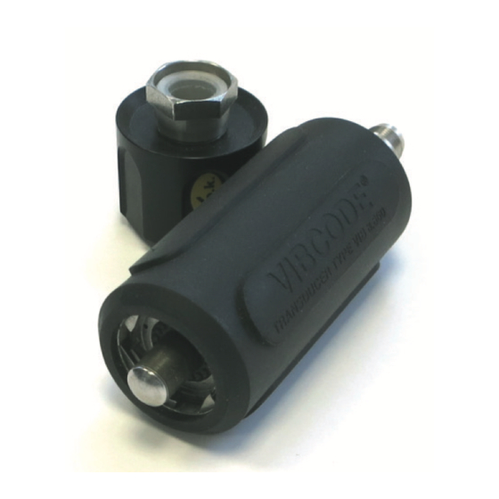
= negligibly small. Disposal • The following devices may also be connected to the VIBCODE VIB 8.660 HEX with their After use, dispose of the sensor in an environ- intrinsically safe analogue output circuits. The mentally friendly manner and in accordance with connection must take place via a cable with a national provisions. - Page 3 Function VIBCODE is a vibration sensor system that uses coded measurement studs for certain identifica- tion of measurement locations on the machine. The system consists of the VIBCODE sensor and the VIBCODE measurement stud. VIBCODE sensor The VIBCODE sensor contains a code ring sensor and a vibration sensor.
- Page 4 VIBCODE stud Distinctive feature VIBCODE studs with screw thread are available A VIBCODE stud consists of a stainless steel bolt, a in two thread sizes and stainless steel qualities. protective cap and a coded plastic ring. Coding is For better differentiation, the threaded bolts are achieved by cutting out individual teeth.
-
Page 5: Technical Data
Technical data Dimensions PARAMETER VIBCODE sensor Signalling system Current Line Drive (CLD) Transmission factor 1.0 µA/ms ± 4% (Ref.: 159 Hz; 25 °C [77°F]) Frequency range ± 3dB 1.5 Hz ... 20 kHz Measurement range r.m.s. 961 ms [ 98 g ] Resonance frequency 36 kHz 136 mm... -
Page 6: Installation
Installation Drill threaded hole • Drill pilot hole: 3.5 mm / 15 mm deep (B). The frequency behavior and dynamic range of • Bore out hole: 6.8 mm / 15 mm deep (C). the VIBCODE sensor can be heavily influenced by •... - Page 7 Notes Excessive torque can damage the thread or the machine housing. Too little torque can allow the stud to work loose. Incorrect torque always causes measurement errors! The tapered shank section must seat perfectly into the countersunk hole so that proper signal trans- fer from the machine to the sensor (left) can take place over a large area of the shank.
- Page 8 Replacing the housing screw A‘ B‘ Required tools and resources – Hand-held drill – Drill bit (> 19 mm) > 35 – 90° countersink bit (VIB 8.694) – Thread tap M8 or UNC 5/16-18 Dimensions in mm – Torque wrench with 19 mm / 3/4“ hex socket –...
-
Page 9: Adhesive Mounting
Adhesive mounting Affix VIBCODE stud • Affix the protective cap to the stud and, if avail- Applies to VIBCODE studs with bonding base. able, insert the code ring into the stud. Required tools and resources • Press the stud gently against the bonding loca- –... -
Page 10: Performing Measurement
Performing measurement After VIBCODE is inserted in the coded measure- ment stud, the measuring device recognizes the measurement location and automatically calls up the measurement tasks for this location. Measure- ment either begins automatically or must be start- ed by pressing a button on the measuring device. Additional details can be found in the measuring device documentation. - Page 11 Cleaning Encoding The stud contains a plastic code • Slight soiling on the sensor can be washed off ring that obtains an unique identity using soap solution or isopropyl and a cotton - similar to a fingerprint - through cloth. the removal of individual teeth.
- Page 12 Company/Certificates-and-Material-Safety/ VIB 9.834.G 08.2018 Fluke Deutschland GmbH 85737 Ismaning, Germany www.pruftechnik.com Productive Maintenance Technology...
Need help?
Do you have a question about the VIBCODE VIB 8.660 and is the answer not in the manual?
Questions and answers