Table of Contents
Advertisement
Thermalert
4.0 Series
®
Smart Integrated Infrared Sensors
Users Manual
PN 4968276, English, Rev. 2.4, Jul 2021
© 2021 Fluke Process Instruments. All rights reserved. Printed in Germany. Specifications subject to change without notice.
All product names are trademarks of their respective companies.
1.800.561.8187
information@itm.com
www.
.com
Advertisement
Table of Contents

Subscribe to Our Youtube Channel
Related Manuals for Fluke Thermalert 4.0 Series


Summary of Contents for Fluke Thermalert 4.0 Series
- Page 1 Smart Integrated Infrared Sensors Users Manual PN 4968276, English, Rev. 2.4, Jul 2021 © 2021 Fluke Process Instruments. All rights reserved. Printed in Germany. Specifications subject to change without notice. All product names are trademarks of their respective companies. 1.800.561.8187 information@itm.com...
-
Page 2: Table Of Contents
Warranty The manufacturer warrants this instrument to be free from defects in material and workmanship under normal use and service for the period of two years from date of purchase. This warranty extends only to the original purchaser. This warranty shall not apply to fuses, batteries or any product which has been subject to misuse, neglect, accident, or abnormal conditions of operation. -
Page 3: Table Of Contents
Table of Contents Chapter Page ..............................3 ABLE OF ONTENTS ............................... 8 IST OF ABLES ..............................9 IST OF IGURES ............................11 OMPLIANCE TATEMENT ............................. 12 AFETY NFORMATION ................................16 ONTACTS ............................... 17 ESCRIPTION ..............................19 ECHNICAL 2.1 Measurement Specification ..................................... 19 2.2 Optical Specifications ...................................... - Page 4 5.4.2 Cable Connection ....................................36 5.4.3 mA Single Loop ..................................... 38 5.4.4 mA Multiple Loops ....................................40 5.4.5 Alarm Output AL ....................................41 5.5 Model HART, 2-Wire ....................................... 42 5.5.1 Back Panel......................................42 5.5.2 Cable Connection ....................................42 5.5.3 mA Loop ........................................ 42 5.5.4 Alarm Output AL ....................................
- Page 5 6.1 Laser ..........................................55 6.2 Post Processing ......................................55 6.2.1 Averaging ....................................... 55 6.2.2 Peak Hold ....................................... 56 6.2.3 Valley Hold ......................................57 6.2.4 Advanced Peak Hold ..................................... 57 6.2.5 Advanced Valley Hold .................................... 58 6.2.6 Advanced Peak Hold with Averaging ..............................58 6.2.7 Advanced Valley Hold with Averaging ..............................
- Page 6 10.4.1 General Settings ....................................70 10.4.2 Emissivity Setting ....................................71 10.4.3 Background Temperature Compensation ............................71 10.4.4 Temperature Hold Functions ................................71 10.5 Sensor Control ......................................72 10.5.1 Analog Output ...................................... 72 10.5.2 Relay Output ......................................72 10.6 RS485 Communication ....................................73 10.7 Multidrop Mode ......................................
- Page 7 14.3 Cleaning the Lens ....................................... 107 15 A ............................... 108 PPENDIX 15.1 Optical Diagrams ......................................108 15.1.1 LT-07 Models ..................................... 108 15.1.2 LT-15 Models ..................................... 108 15.1.3 LT-30 Models ..................................... 109 15.1.4 LTB-30 Models ....................................110 15.1.5 LT-50 Models ..................................... 111 15.1.6 LT-70 Models .....................................
-
Page 8: List Of Tables
List of Tables Table Page Table 5-1: Terminal Connections ....................................35 Table 5-2: Test Modes ........................................ 35 Table 5-3: Power Supply Requirements for Multiple Loads ............................40 Table 5-4: Terminal Connections ....................................42 Table 5-5: Pin Assignment for Terminal Strip ................................47 Table 5-6: Pin Assignment for DIN Connector ................................ - Page 9 List of Figures Figure Page Figure 1-1: Available Models ....................................... 18 Figure 2-1: Dimensions for the 2-Wire and 6-Wire Model ............................27 Figure 2-2: Dimensions for the 4-Wire Model, Fieldbus ............................. 27 Figure 2-3: Dimensions for the 12-Wire Model ................................28 Figure 4-1: One Earth Ground at the Sensor (left) or at the Power Supply (right) .....................
- Page 10 Figure 13-7: Industrial Power Supply ..................................85 Figure 13-8: Power Supply with Terminal Box ................................86 Figure 13-9: USB/RS485 Converter ................................... 88 Figure 13-10: PoE Injector ......................................89 Figure 13-11: Overview to Mechanical Accessories..............................90 Figure 13-12: Mounting Nut ......................................91 Figure 13-13: Fixed Bracket ......................................
-
Page 11: Compliance Statement
Compliance Statement The device complies with the requirements of the European Directives: EC – Directive 2014/30/EU – EMC EC – Directive 2011/65/EU – RoHS II EC – Directive 2014/34/EU – ATEX valid for device: T40-xx-xx-xxx-x-IS EN 61326-1: 2013 Electrical measurement, control and laboratory devices - Electromagnetic susceptibility (EMC) EN 50581: 2012 Technical documentation for the evaluation of electrical products with respect to... -
Page 12: Safety Information
Safety Information This document contains important information, which should be kept at all times with the instrument during its operational life. Other users of this instrument should be given these instructions with the instrument. Eventual updates to this information must be added to the original document. The instrument can only be operated by trained personnel in accordance with these instructions and local safety regulations. - Page 13 Exemplary product label for standard model Exemplary product label for HART model Exemplary product for model with intrinsically-safe rating 1.800.561.8187 information@itm.com www. .com...
- Page 14 Safety Symbol Description Read all safety information before in the handbook Hazardous voltage. Risk of electrical shock. Warning. Risk of danger. Important information. See manual. Laser warning Earth (ground) terminal Protective conductor terminal Switch or relay contact DC power supply Conforms to European Union directive.
-
Page 15: Contacts
To prevent possible electrical shock, fire, or personal injury follow these guidelines: • Read all safety information before you use the product. • Use the product only as specified, or the protection supplied by the product can be compromised. • Do not use the product around explosive gases, vapor, or in damp or wet environments. •... -
Page 16: Description
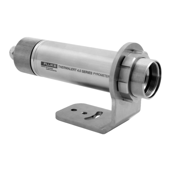
The Thermalert 4.0 sensor is an infrared thermometer that differs in spectral responses to be capable of covering a broad range of applications such as metal, glass, and plastics. The Thermalert 4.0 Series introduces improved temperature measurement specifications, an extended operating ambient temperature range, multiple user interfaces and various network communications. Everything is packaged in a sealed stainless-steel housing rated IP65 (NEMA 4). -
Page 17: Figure 1-1: Available Models
® Thermalert 4.0 Series Users Manual, Rev. 2.4, Jul 2021 Figure 1-1: Available Models 2-Wire 4-Wire 4 to 20 mA, Alarm, USB Ethernet, EtherNet/IP, PROFINET IO 6-Wire 12-Wire Analog Out, RS485, USB Analog In/Out, Alarm, Trigger, RS485, USB 1.800.561.8187 information@itm.com www. -
Page 18: Technical Data
Technical Data Measurement Specification 2 Technical Data 2.1 Measurement Specification Temperature Range LT-07 -20 to 600°C (-4 to 1112°F) LT-15 -20 to 600°C (-4 to 1112°F) LT-30 -20 to 600°C (-4 to 1112°F) LTB-30 -20 to 600°C (-4 to 1112°F) LT-50 -40 to 1000°C (-40 to 1832°F) LT-70... - Page 19 ® Thermalert 4.0 Series Users Manual, Rev. 2.4, Jul 2021 1ML-150 1 µm 1MH-150 1 µm Response Time LT-07 150 ms LT-15 150 ms LT-30 30 ms LTB-30 30 ms LT-50 130 ms LT-70 130 ms LTD-04 150 ms P7-30 130 ms G7-70 130 ms...
- Page 20 Technical Data Measurement Specification Temperature Resolution Digital output 0.1°C (0.1°F) Analog output 14 bit Emissivity 4-, 6-, 12-wire models 0.100 to 1.100, in 0.001 increments 2-wire models 0.10 to 1.00, in 0.01 increments Signal Processing All models Averaging, peak hold, valley hold, advanced peak hold, advanced valley hold, ambient background temperature compensation 1.800.561.8187 information@itm.com...
-
Page 21: Optical Specifications
® Thermalert 4.0 Series Users Manual, Rev. 2.4, Jul 2021 2.2 Optical Specifications Optical Resolution Focus Distances LT-07 CF0 (plastic lens) LT-15 15:1 SF0 (plastic lens) LT-30 33:1 SF0, CF1, CF2 LTB-30 33:1 SF0, CF1, CF2 LT-50 50:1 SF0, CF2 LT-70 70:1 SF2, CF2... - Page 22 Technical Data Optical Specifications Smallest Measurement Spot LT-07-CF 7.1 mm (0.28 in) LT-30-CF1 2.3 mm (0.09 in) LT-30-CF2 6.1 mm (0.24 in) LTB-30-CF1 2.3 mm (0.09 in) LTB-30-CF2 6.1 mm (0.24 in) LT-50-CF2 4 mm (0.16 in) LT-70-SF2 17.9 mm (0.7 in) LT-70-CF2 2.9 mm (0.11 in) G7-70-SF2...
-
Page 23: Electrical Specifications
® Thermalert 4.0 Series Users Manual, Rev. 2.4, Jul 2021 2.3 Electrical Specifications 2.3.1 Model 2-Wire Power 12 to 28.8 VDC Outputs Analog 4 to 20 mA, loop impedance max. 500 Ω Alarm 24 V / 150 mA version 2.0, micro-B connector (only for the setup of the instrument) 2.3.2 Model HART, 2-Wire Power 12 to 28.8 VDC... -
Page 24: Model 6-Wire
Technical Data Electrical Specifications 2.3.4 Model 6-Wire Power + 24 VDC nominal (20 to 48 VDC), 100 mA @ 24 V Outputs Analog 0 to 20 mA (active), or 4 to 20 mA (active), or 0 to 10 V, or J thermocouple, or K thermocouple current loop impedance: max. -
Page 25: Environmental Specifications
® Thermalert 4.0 Series Users Manual, Rev. 2.4, Jul 2021 2.4 Environmental Specifications Ingress Protection IP65 / IEC 60529 (NEMA-4) Operating temperature -20 to 85°C (-4 to 185°F) without cooling 10 to 120°C (50 to 250°F) with air cooling 10 to 175°C (50 to 350°F) with water cooling 10 to 315°C (50 to 600°F) water cooled by ThermoJacket IS rated models -20 to 80°C (-4 to 176°F) without cooling... -
Page 26: Dimensions
Technical Data Dimensions 2.5 Dimensions 2.5.1 Model 2-Wire / 6-Wire Figure 2-1: Dimensions for the 2-Wire and 6-Wire Model 2.5.2 Model Fieldbus, 4-Wire Figure 2-2: Dimensions for the 4-Wire Model, Fieldbus 1.800.561.8187 information@itm.com www. .com... -
Page 27: Model 12-Wire
® Thermalert 4.0 Series Users Manual, Rev. 2.4, Jul 2021 2.5.3 Model 12-Wire Figure 2-3: Dimensions for the 12-Wire Model 1.800.561.8187 information@itm.com www. .com... -
Page 28: Scope Of Delivery
Technical Data Scope of Delivery 2.6 Scope of Delivery The scope of delivery includes the following: • Sensor • Mounting nut (not for LTB model) • Fixed bracket (not for LTB model) • USB cable, only for the setup of the instrument (not for LTB and 4-wire models) Operator's manual (as pdf file on data carrier) •... -
Page 29: Basics
® Thermalert 4.0 Series Users Manual, Rev. 2.4, Jul 2021 3 Basics 3.1 Measurement of Infrared Temperature All surfaces emit infrared radiation. The intensity of this infrared radiation changes according to the temperature of the object. Depending on the material and surface properties, the emitted radiation lies in a wavelength spectrum of approximately 1 to 20 µm. -
Page 30: Environment
Environment Ambient Temperature 4 Environment 4.1 Ambient Temperature In many cases there is a poor understanding of the actual temperatures at the site where the sensor is mounted. While process temperatures are typically very well monitored and controlled, there is ambient conditions around the process have no bearing on product throughput or quality and therefore remain unknown. -
Page 31: Figure 4-2: Principle Of The Galvanic Isolation For The 6-Wire Model
® Thermalert 4.0 Series Users Manual, Rev. 2.4, Jul 2021 Note All inputs and outputs are electrically NOT connected to the power supply (except the alarm output for the 2-wire model). Figure 4-2: Principle of the Galvanic Isolation for the 6-Wire Model Isolation + VDC + Analog Out... -
Page 32: Installation
Installation Positioning 5 Installation Risk of Personal Injury When this instrument is being used in a critical process that could cause property damage and personal injury, the user should provide a redundant device or system that will initiate a safe process shutdown in the event that this instrument should fail. -
Page 33: Viewing Angles
® Thermalert 4.0 Series Users Manual, Rev. 2.4, Jul 2021 5.3 Viewing Angles The sensor head can be placed at any angle from the target less than 45°. Figure 5-2: Acceptable Sensor Viewing Angles Best perpendicular to target Acceptable Angles Good up to 45°... -
Page 34: Model 2-Wire
Installation Model 2-Wire 5.4 Model 2-Wire The 2-wire model provides a standard two-wire current loop output and USB communications. 5.4.1 Back Panel The rear panel supports a 3-pin terminal for connecting the alarm output (AL) and the 4 to 20 mA current loop. The polarity is indicated on the panel. -
Page 35: Cable Connection
® Thermalert 4.0 Series Users Manual, Rev. 2.4, Jul 2021 5.4.2 Cable Connection The sensor cable must be provided by the user. Note The cable must include shielded wires. The screwed cable gland described below is not a strain relief! Consequently, the cable must be clamped accordingly during the installation. - Page 36 Installation Model 2-Wire Step 4 Put the following on the cable: the PG nut (1) and the relief bushing (2). Step 5 Prepare the cable. Remove about 6 cm (2.36 in) of the insulation. Shorten the shield to about 1 cm (0.4 in). Tin-coat the connecting leads if not done yet.
-
Page 37: Ma Single Loop
5.4.3 mA Single Loop The 2-wire model of the Thermalert 4.0 Series is an infrared thermometer with a built-in two-wire transmitter. Power it up with an appropriate direct current source and you get a 4 to 20 mA current. The current varies with target temperature over the full temperature span of the instrument. -
Page 38: Figure 5-4: Principle Circuit Diagram: Infrared Sensor With Multiple Loads
Installation Model 2-Wire You can use this current to operate a 4 to 20 mA indicator, recorder, controller or data logger – or a combination of devices in the series. The following figure illustrates a simple system consisting of the infrared sensor, a digital meter and a power supply. -
Page 39: Ma Multiple Loops
® Thermalert 4.0 Series Users Manual, Rev. 2.4, Jul 2021 With 2 V dropped across the load elements and cables, a supply voltage of at least 14 V is needed to ensure the required 12 V minimum for the infrared sensor: ��... -
Page 40: Alarm Output Al
Installation Model 2-Wire Figure 5-6: Principle Circuit Diagram: Infrared Sensor with Multiple Loads Controllers Infrared Sensors Indicators Loop1 Loop2 Power Supply Loop 5.4.5 Alarm Output AL The maximum current carrying capacity for the alarm output is 150 mA. Use the circuit diagram below. The alarm output AL of the instrument is not electrically isolated from the power supply. -
Page 41: Model Hart, 2-Wire
® Thermalert 4.0 Series Users Manual, Rev. 2.4, Jul 2021 5.5 Model HART, 2-Wire The HART model provides digital communication via a standard two-wire current loop output. 5.5.1 Back Panel The rear panel supports a 3-pin terminal for connecting the alarm output (AL) and the 4 to 20 mA current loop. The polarity is indicated on the panel. -
Page 42: Model Fieldbus, 4-Wire
Installation Model Fieldbus, 4-Wire 5.6 Model Fieldbus, 4-Wire 5.6.1 Wiring The 4-wire model fieldbus supports a M12 plug-in connector, 4 pin D-coded, and a screw retention feature. Figure 5-9: M12 Connector Socket and Pin Assignment M12-Pin For appropriate cables, see section 13.1.3 Ethernet PoE Cable (A-CB-xx-M12-W04-xx), page 82. -
Page 43: Reset Addressing
® Thermalert 4.0 Series Users Manual, Rev. 2.4, Jul 2021 Port: In the case that the default port for the sensor should conflict with something else (it could be blocked by the firewall for example) it can be changed using the ASCII command <PORT>. Gateway: A gateway connects two subnets (which have a different subnet address). - Page 44 Installation Model Fieldbus, 4-Wire Click on <Properties>: Under <This connection uses the following items> select <Internet Protocol (TCP/IPv4)> and click on <Properties>: Activate the radio button <Use the following IP address> and make the following settings: IP address: 192.168.42.x where x is an address between 0 and 255 except 134 which is already used by the Thermalert 4.0 sensor by factory default Subnet mask: 255.255.255.0...
-
Page 45: Ascii Programming
® Thermalert 4.0 Series Users Manual, Rev. 2.4, Jul 2021 Close all dialog boxes by pressing on <OK>. 5.6.4 ASCII Programming For the programming details, see section 10 ASCII Programming, page 69. 5.6.5 http Server The Thermalert 4.0 sensor with Ethernet provides a built-in http server for one or more client computers based on the http protocol within an Intranet. -
Page 46: Cable Connection
5.7.4 Analog Out The 6-wire model of the Thermalert 4.0 Series is an infrared thermometer with a built-in analog output to drive analog devices. The output can be configured to output mA, V, or TC by means of software or a dedicated ASCII command. -
Page 47: Tc Output
® Thermalert 4.0 Series Users Manual, Rev. 2.4, Jul 2021 Figure 5-14: Wiring Analog Out as Voltage Output 5.7.4.3 TC Output The output can be configured as thermocouple output type J or K. For a TC output, you must install a dedicated compensation cable. -
Page 48: Ftc1 - Emissivity Setting
Installation Model 12-Wire 5.8.3 FTC1 – Emissivity Setting The FTC1 input can be configured to accept an analog voltage signal (0 to 10 VDC) to provide real time emissivity setting. The following table shows the relationship between input voltage and emissivity: Table 5-7: Ratio between Analog Input Voltage and Emissivity (Example) U in V …... -
Page 49: Trigger Input
® Thermalert 4.0 Series Users Manual, Rev. 2.4, Jul 2021 • If the background temperature is known and constant, the user may give the known background temperature as a constant temperature value. • Background temperature compensation from a second temperature sensor (infrared or contact temperature sensor) ensures extremely accurate results. -
Page 50: Reset
Installation Model 12-Wire Figure 5-19: Wiring the Trigger Input Sensor Trigger (F) GND (L) 5.8.5.1 Reset A logical low signal at the trigger input pauses the peak or valley hold function. As long as the input is kept at logical low level, the instrument will transfer the actual object temperatures toward the output. At the next logical high level, the peak or valley hold function will be restarted. -
Page 51: Laser
5.8.7 Analog Out The 12-wire model of the Thermalert 4.0 Series is an infrared thermometer with a built-in analog output to drive analog devices. The output can be configured to output mA or V by means of software or a dedicated ASCII command. -
Page 52: Output
Installation Model 12-Wire A specific feature for the testing or calibrating of connected equipment allows the current loop output to be set to specific values, under range or over range using a dedicated ASCII command. Via such functionality, you can force the instrument, operating in the 4-20 mA mode, to transmit an output current less than 4 mA (e.g., 3.5 mA) or above 20 mA (e.g., 21.0 mA). -
Page 53: Model Ltd-04
® Thermalert 4.0 Series Users Manual, Rev. 2.4, Jul 2021 5.9 Model LTD-04 5.9.1 Assembly The LTD-04 model consists of two components, the sensor itself and a special air purge. These two components are supplied separately in an unassembled state. Therefore, before installation, the LTD-04 model must be assembled as follows: Make sure that the supplied mounting bracket - or an adequate mounting fixture - is attached to the sensor with the mounting nut. -
Page 54: Operation
Operation Laser 6 Operation 6.1 Laser The laser sighting allows fast and precise aiming at small, rapidly moving targets, or targets passing at irregular intervals. The laser is specially aligned with the sensor’s lens to provide accurate, non-parallax pinpointing of targets. -
Page 55: Figure 6-2: Averaging
® Thermalert 4.0 Series Users Manual, Rev. 2.4, Jul 2021 Note The disadvantage of averaging is the time delay of the output signal. If the temperature jumps at the input (hot object), the output signal reaches only 90% magnitude of the actual object temperature after the defined average time. -
Page 56: Figure 6-4: Valley Hold
Operation Post Processing 6.2.3 Valley Hold The output signal follows the object temperature until a minimum is reached. The output will „hold“ the minimum value for the selected duration of the hold time. Once the hold time is exceeded, the valley hold function will reset and the output will resume tracking the object temperature until a new valley is reached. -
Page 57: Figure 6-6: Advanced Peak Hold With Averaging
® Thermalert 4.0 Series Users Manual, Rev. 2.4, Jul 2021 The advanced peak hold function requires the setting of the following ASCII commands: Hysteresis XY > 0 // activates advanced peak hold Advanced Hold Time AA = 0 // deactivates the averaging for advanced peak hold Threshold C // sets the value for the temperature threshold 6.2.5 Advanced Valley Hold... -
Page 58: Figure 7-1: Network In Linear Topology (Daisy Chain)
RS485 Specification 7 RS485 The RS485 serial interface is used for networked sensors or for long distances up to 1200 m (4000 ft). This allows ample distance from the harsh environment where the sensing system is mounted to a control room or pulpit where the computer is located. -
Page 59: Figure 7-2: Rs485 Communication For 6-Wire Model
® Thermalert 4.0 Series Users Manual, Rev. 2.4, Jul 2021 7.3 Wiring 7.3.1 Model 6-Wire Figure 7-2: RS485 Communication for 6-Wire Model negative signal RS485-B positive signal RS485-A 7.3.2 Model 12-Wire Figure 7-3: RS485 Communication for 12-Wire Model Sensor RS485-B (B) RS485-A (A) GND (L) +VDC (M) -
Page 60: Figure 7-4: Wiring The Sensor's Rs485 Interface With Usb/Rs485 Converter In 2-Wire Mode
RS485 Wiring Figure 7-4: Wiring the Sensor’s RS485 Interface with USB/RS485 Converter in 2-Wire Mode Sensor USB/RS485 Converter 7.3.4 Multiple Sensors For an installation of two or more sensors in a RS485 network (2-wire, half duplex), each sensor needs its specific RS485 network address (1 - 32). - Page 61 ® Thermalert 4.0 Series Users Manual, Rev. 2.4, Jul 2021 7.4 ASCII Programming For the programming details, see section 10 ASCII Programming, page 69. 1.800.561.8187 information@itm.com www. .com...
- Page 62 PROFINET IO Configuration 8 PROFINET IO The PROFINET IO maps the object temperature, internal temperature and the status of the pyrometer via PROFINET IO. Furthermore, PROFINET IO allows you to change a subset of sensor parameters in data exchange mode. In the initialization phase, the PROFINET module determines the physical structure of the node and creates a local process image with the pyrometer.
-
Page 63: Table 8-1: Pyrometer Parameters
® Thermalert 4.0 Series Users Manual, Rev. 2.4, Jul 2021 Table 8-1: Pyrometer Parameters Parameter Description Setting Temperature unit Set the temperature unit Celsius, Fahrenheit Emissivity *1000, in thousandths (0.9 → 900) 100…1100 Transmissivity *1000, in thousandths (1.0 → 1000) 100…1100 Average Time *0.1 s, in tenths (1 s →... -
Page 64: Table 8-5: Parameter Types
PROFINET IO Diagnostics The <Type of parameter> gives the meaning of the following parameters with the same format as described in section 8.2 Parameters, page 63. Table 8-5: Parameter Types Type of parameter Meaning Format Do not change anything Emissivity REAL Transmissivity REAL... -
Page 65: Table 9-1: Pyrometer Parameters
® Thermalert 4.0 Series Users Manual, Rev. 2.4, Jul 2021 9 EthernNet/IP The EtherNet/IP module maps the object temperature, internal temperature, device status and other pyrometer data to its input assembly which is then sent onto the EtherNet/IP network using CIP. In the initialization phase, the device sends configuration data which is accessible for setup via the PLC programming software controller tags. -
Page 66: Table 9-2: Input Data
EthernNet/IP Input Data 9.3 Input Data Table 9-2: Input Data Address without offset Length Format Value 4 Byte REAL (Big Endian, Motorola) Target temperature 4 Byte REAL (Big Endian, Motorola) Internal temperature 4 Byte DWORD Error code The data must be processed (copied) into especially created tags in a correct format in accordance to column “Format”. -
Page 67: Table 9-5: Error Codes
® Thermalert 4.0 Series Users Manual, Rev. 2.4, Jul 2021 It can be translated using the table below. Table 9-5: Error Codes Description Internal temperature over range Internal temperature under range Object temperature under range Object temperature over range EtherNet/IP not ready 1.800.561.8187 information@itm.com www. - Page 68 ASCII Programming Command Structure 10 ASCII Programming This section explains the sensor’s communication protocol. A protocol is the set of commands that define all possible communications with the sensor. The commands are described along with their associated ASCII command characters and related message format information. Use them when writing custom programs for your applications or when communicating with your sensor with a terminal program.
-
Page 69: Table 10-1: Sensor Information
® Thermalert 4.0 Series Users Manual, Rev. 2.4, Jul 2021 • “*Syntax Error” – a value entered in an incorrect format 10.2 Transfer Modes There are two possible transfer modes for the serial interface. Poll Mode: The current value of any individual parameter can be requested by the host. The sensor responds once with the value at the selected baud rate. - Page 70 ASCII Programming Sensor Setup A=250 sets the ambient background temperature compensation according to the setting of “AC” command, see section 10.4.3 Background Temperature Compensation, page 71. XG=1.000 sets the transmission asks for the target temperature asks for the internal temperature of the sensor asks for the energy value of the target temperature 10.4.2 Emissivity Setting The emissivity setting is selected by means of the “ES”...
-
Page 71: Table 10-2: Overview To Temperature Hold Functions
® Thermalert 4.0 Series Users Manual, Rev. 2.4, Jul 2021 Table 10-2: Overview to Temperature Hold Functions Hold Function RESET by Peak Time Valley Time Threshold Hystersis Protocol code None none 000.0 000.0 Peak Hold timer 000.0-998.9 000.0 000.0 Peak Hold trigger Holds infinitely 000.0... - Page 72 ASCII Programming RS485 Communication alarm output triggered by internal sensor case temperature, N.C. normally closed XS=125.3 sets the upper alarm threshold to 125.3 in current scale. The alarm threshold is used for the target temperature only (see command XS). 10.6 RS485 Communication The serial RS485 communication is in 2-wire mode.
-
Page 73: Figure 11-1: Typical Installation With Hart Adapter
® Thermalert 4.0 Series Users Manual, Rev. 2.4, Jul 2021 11 HART Communication 2-wire sensing heads with HART communication transmit information in two directions. On the one hand, the sensing head provides analog measured values to the control room via the 4 to 20 mA current loop. On the other hand, the sensing head can be reprogrammed from the control room by means of bi-directional transmission of digital signals. - Page 74 ASCII Command List 12 Intrinsic Safety The HART model for the Thermalert 4.0 series is available as intrinsic safety rated sensing head (-IS) intended for use in explosive atmospheres. The model T40-xx-xx-xxx-6-IS follows the ATEX / IECEx certification in accordance to:...
-
Page 75: Figure 12-1: Intrinsic Safety Installation With Power Supply Barrier From Company Pepperl+Fuchs (Example)
® Thermalert 4.0 Series Users Manual, Rev. 2.4, Jul 2021 12.1 Power Supply Barrier The intrinsically safe sensor requires a power supply barrier which must be ordered separately from a third-part vendor. The manufacturer recommends using the following power supply barrier: Company Pepperl+Fuchs, model KCD2-STC-EX1 •... - Page 76 Accessories Electrical Accessories 13 Accessories 13.1 Electrical Accessories The following electrical accessories are available: • 12-Wire Cable, High Temp (A-CB-HT-M16-W12-xx) • 12-Wire Cable, Low Temp (A-CB-LT-M16-W12-xx) • Ethernet PoE Cable (A-CB-xx-M12-W04-xx) • Terminal Block (A-T40-TB) • Terminal Block with Enclosure (A-T40-TB-ENC) •...
-
Page 77: Table 13-1: Cable Specification
® Thermalert 4.0 Series Users Manual, Rev. 2.4, Jul 2021 13.1.1 12-Wire Cable, High Temp (A-CB-HT-M16-W12-xx) Use the High Temp 12-wire cable for the sensor to support power supply, all inputs, outputs, and the RS485 interface. The cable described below is a shielded 12-conductor cable, made of two twisted pairs plus 8 separate wires, all as tinned copper braid. - Page 78 Accessories Electrical Accessories Risk of Personal Injury Teflon develops poisonous gasses when it is exposed to flames! Note An ordered cable does not include a terminal block! Note If you cut the cable to shorten it, notice that both sets of twisted-pair wires have drain wires inside their insulation.
-
Page 79: Table 13-3: Cable Specification
® Thermalert 4.0 Series Users Manual, Rev. 2.4, Jul 2021 13.1.2 12-Wire Cable, Low Temp (A-CB-LT-M16-W12-xx) Use the Low Temp 12-wire cable for the sensor to support power supply, all inputs, outputs, and the RS485 interface. The cable described below is a shielded 12-conductor cable, made of two twisted pairs plus 8 separate wires, all as tinned copper braid. - Page 80 Accessories Electrical Accessories Risk of Personal Injury Polyurethane may cause allergy and possibly cancer! Note An ordered cable does not include a terminal block! Note If you cut the cable to shorten it, notice that both sets of twisted-pair wires have drain wires inside their insulation.
-
Page 81: Table 13-5: Available Ethernet Poe Cables
® Thermalert 4.0 Series Users Manual, Rev. 2.4, Jul 2021 13.1.3 Ethernet PoE Cable (A-CB-xx-M12-W04-xx) The Ethernet PoE cable comes with a four-pin male M12 D-coded connector, assigned to the sensors rear female M12 connector. The corresponding end of the Ethernet PoE cable is equipped with a general RJ45 snap-in connector. -
Page 82: Figure 13-5: Terminal Block With Wire Color Assignment
Accessories Electrical Accessories 13.1.4 Terminal Block (A-T40-TB) The terminal block accessory is for the connection of the sensor to the customer’s industrial environment. It lists all different conductor colors on one side and the related signal names on the other side. Terminal Block with Wire Color Assignment Figure 13-5: to the Sensor... -
Page 83: Figure 13-6: Terminal Block In An Enclosure
® Thermalert 4.0 Series Users Manual, Rev. 2.4, Jul 2021 13.1.5 Terminal Block with Enclosure (A-T40-TB-ENC) The terminal block accessory in an enclosure is for the connection of the Thermalert 4.0 sensor to the customer’s industrial environment. The enclosure is IP67 (NEMA 4) protected, and the terminal block inside is identical to part A-T40-TB. -
Page 84: Figure 13-7: Industrial Power Supply
Accessories Electrical Accessories 13.1.6 Power Supply DIN Rail (A-PS-DIN-24V) The DIN-rail mount industrial power supply delivers isolated DC power and provides short circuit and overload protection. Risk of Personal Injury To prevent electrical shocks, the power supply must be used in protected environments (cabinets)! Technical data: Protection class... -
Page 85: Figure 13-8: Power Supply With Terminal Box
® Thermalert 4.0 Series Users Manual, Rev. 2.4, Jul 2021 13.1.7 Power Supply with Terminal Box (A-PS-ENC-24V) The terminal box for the power supply is designed to provide IP65 (NEMA-4) protection to the terminal block, see section 13.1.4 Terminal Block, page 83, and a power supply for the sensor. The terminal box should be surface mounted using the flanges and holes provided. - Page 86 Accessories Electrical Accessories To ensure correct wiring, stick the enclosed sticker onto the carrier plate as shown below. FTC2 FTC1 +A Out AGND 1.800.561.8187 information@itm.com www. .com...
-
Page 87: Figure 13-9: Usb/Rs485 Converter
® Thermalert 4.0 Series Users Manual, Rev. 2.4, Jul 2021 13.1.8 USB/RS485 Converter (A-CONV-USB485) The USB/RS485 converter allows you to connect your sensor to computers by using an USB interface. Technical Data Power supply 5 VDC direct from USB port Speed max. -
Page 88: Figure 13-10: Poe Injector
Accessories Electrical Accessories 13.1.9 PoE Injector (A-POE) The PoE injector allows you to power the Thermalert 4.0 sensor over the Ethernet connection. Technical Data PoE standard 802.3af PoE output power 15.4 W PoE ports Ethernet 100Base TX Power supply 100 to 240 VAC / 50 to 60 Hz, 19 W Operating temperature 0 to 50°C (32 to 122°F) Humidity... -
Page 89: Figure 13-11: Overview To Mechanical Accessories
® Thermalert 4.0 Series Users Manual, Rev. 2.4, Jul 2021 13.2 Mechanical Accessories The following mechanical accessories are available: • Mounting Nut (A-MN) • Fixed Bracket (A-BR-F) • Adjustable Bracket (A-BR-A) • Swivel Bracket (A-BR-S) • Sighting Tube (A-ST-xx) • Pipe Adapter (A-PA) •... -
Page 90: Figure 13-12: Mounting Nut
Accessories Mechanical Accessories 13.2.1 Mounting Nut (A-MN) See below for the standard mounting nut with an inner thread of 1.5” UNC to fix and secure the Thermalert 4.0 sensor to any kind of mounting brackets. Figure 13-12: Mounting Nut 1.800.561.8187 information@itm.com www. -
Page 91: Figure 13-13: Fixed Bracket
® Thermalert 4.0 Series Users Manual, Rev. 2.4, Jul 2021 13.2.2 Fixed Bracket (A-BR-F) The fixed bracket enables the Thermalert 4.0 sensor to be mounted in a fixed location. For a correct horizontal sensor orientation, a swivel range within 45° is available. Figure 13-13: Fixed Bracket 1.800.561.8187 information@itm.com... -
Page 92: Figure 13-14: Adjustable Bracket
Accessories Mechanical Accessories 13.2.3 Adjustable Bracket (A-BR-A) The adjustable bracket enables the Thermalert 4.0 sensor to be mounted in a movable location. For a correct sensor orientation, you can pitch and swivel the sensor sighting axis in a range of about 45° per axis. Figure 13-14: Adjustable Bracket 1.800.561.8187 information@itm.com... -
Page 93: Figure 13-15: Swivel Bracket
® Thermalert 4.0 Series Users Manual, Rev. 2.4, Jul 2021 13.2.4 Swivel Bracket (A-BR-S) The swivel bracket enables the Thermalert 4.0 sensor to be mounted in a movable position, to correct in an easy way the pitch and yaw orientation of the sensor. For a correct sensor orientation, you are able to pitch (0° – 90°) and to swivel (0°... -
Page 94: Figure 13-16: Installation Of The Sighting Tube
Accessories Mechanical Accessories 13.2.5 Sighting Tube (A-ST-xx) The sighting tube is used in environmental conditions where reflected energy is a problem. Fix the pipe adapter (A-PA) directly to the sensor and screw the sighting tube into the pipe adapter. Figure 13-16: Installation of the Sighting Tube Sensor Pipe Adapter (A-PA) -
Page 95: Figure 13-18: Available Sighting Tubes
® Thermalert 4.0 Series Users Manual, Rev. 2.4, Jul 2021 Figure 13-18: Available Sighting Tubes Sighting Tube Ceramic (A-ST-CER) Sighting Tube Stainless Steel (A-ST-SS) Sighting Tube Carbon Steel (A-ST-CS-45) Note When using a customer supplied sighting tube, use caution in specifying the inside diameter and length. Your sensing head determines what diameter/length combinations are possible without impeding the optical field of view! For this reason, the Thermalert 4.0 sensors LT-07 and LT-15 cannot be combined with the above sighting... -
Page 96: Figure 13-19: Pipe Adapter
Accessories Mechanical Accessories 13.2.6 Pipe Adapter (A-PA) The pipe adapter is used to adapt the sighting tube (A-ST-xx) to the Thermalert 4.0 sensor, see section 13.2.5 Sighting Tube, page 95. The adapter has two inner threads to adapt the outer thread of the instrument (1.5” UNC) to the outer thread of the sighting tube (1.5”... -
Page 97: Table 13-6: Protective Windows
® Thermalert 4.0 Series Users Manual, Rev. 2.4, Jul 2021 13.2.7 Protective Windows (A-T40-PW-xx) Protective windows can be used to protect the sensor’s optics against dust and other contamination. Figure 13-20: Protective Window The following table provides an overview of the available protective windows recommended for the spectral models. -
Page 98: Figure 13-21: Right Angle Mirror
Accessories Mechanical Accessories 13.2.8 Right Angle Mirror (A-MIR-RA) The right angle mirror is to redirect the measured object temperature spot at an angle of 90°. This allows placing the Thermalert 4.0 sensor closer to the object to measure or in a more protected domain. To keep the inserted mirror dust and dirt clean, the right angle mirror has an air-purge adapter and needs to be supplied by air. -
Page 99: Figure 13-22: Air Purge
® Thermalert 4.0 Series Users Manual, Rev. 2.4, Jul 2021 13.2.9 Air Purge (A-AP) The air purge is used to keep dust, moisture, airborne particles, and vapors away from the lens. It can be mounted before or after the bracket. It must be screwed in fully. Air flows into the 1/8” NPT fitting and out the front aperture. Airflow should be a maximum of 0.5 to 1.5 l/s (0.13 to 0.4 gallons/s). -
Page 100: Figure 13-23: Air/Water-Cooled Housing
Accessories Mechanical Accessories 13.2.10 Air/Water-Cooled Housing (A-T40-WC) The air/water-cooled housing allows the sensor to be used in ambient temperatures up to 120°C (250°F) with air cooling, and 180°C (356°F) with water cooling. The cooling media should be connected using 1/8” NPT fittings requiring 6 mm (0.24 in) inner diameter and 8 mm (0.31 in) outer diameter for the tube. - Page 101 ® Thermalert 4.0 Series Users Manual, Rev. 2.4, Jul 2021 13.2.10.1 Avoidance of Condensation If environmental conditions make water cooling necessary, it is strictly recommended to check whether condensation will be a real problem or not. Water-cooling also causes a cooling of the air in the inner part of the sensor, thereby decreasing the capability of the air to hold water.
-
Page 102: Table 13-7: Minimum Device Temperatures [°C/°F]
Accessories Mechanical Accessories Table 13-7: Minimum device temperatures [°C/°F] Relative Humidity [%] 100/ Example: Ambient temperature = 50°C Relative humidity = 40 % Minimum device temperature = 30°C The use of lower temperatures is at your own risk! 1.800.561.8187 information@itm.com www. -
Page 103: Figure 13-24: Thread Adapter
® Thermalert 4.0 Series Users Manual, Rev. 2.4, Jul 2021 13.2.11 Thread Adapter (A-TA-M56) The thread adapter is secured to the front of the Thermalert 4.0 sensor. It provides an outer M56 thread to fit to legacy Marathon MM installations. The thread adapter is also used to hold the mounting flange (A-MF-MOD) for use in existing Ircon flange mount installations. -
Page 104: Figure 13-25: Mounting Flange
Accessories Mechanical Accessories 13.2.12 Mounting Flange (A-MF-MOD) The mounting flange provides a footprint to allow the Thermalert 4.0 sensor to be mounted into a legacy Ircon Modline flange mount installations. Please note that this accessory needs to be used in conjunction with the thread adapter (A-TA-M56) to adapt the outer thread of the Thermalert 4.0 to the inner thread of the flange. -
Page 105: Table 14-1: Troubleshooting
® Thermalert 4.0 Series Users Manual, Rev. 2.4, Jul 2021 14 Maintenance Our sales representatives and customer service staff are always at your disposal for questions regarding applications, calibration, repair, and solutions to specific problems. Please contact your local sales representative if you need assistance. - Page 106 Maintenance Cleaning the Lens 14.3 Cleaning the Lens Always keep the lens clean. Care should be taken when cleaning the lens. To clean the lens, do the following: Lightly blow off loose particles with “canned” air (used for cleaning computer equipment) or a small squeeze bellows (used for cleaning camera lenses).
-
Page 107: Figure 15-1: Optical Diagrams Lt-07 Models
® Thermalert 4.0 Series Users Manual, Rev. 2.4, Jul 2021 15 Appendix 15.1 Optical Diagrams 15.1.1 LT-07 Models Figure 15-1: Optical Diagrams LT-07 Models 15.1.2 LT-15 Models Figure 15-2: Optical Diagrams LT-15 Models 1.800.561.8187 information@itm.com www. .com... -
Page 108: Figure 15-3: Optical Diagrams Lt-30 Models
Appendix Optical Diagrams 15.1.3 LT-30 Models Figure 15-3: Optical Diagrams LT-30 Models 1.800.561.8187 information@itm.com www. .com... -
Page 109: Figure 15-4: Optical Diagrams Ltb-30 Models
® Thermalert 4.0 Series Users Manual, Rev. 2.4, Jul 2021 15.1.4 LTB-30 Models Figure 15-4: Optical Diagrams LTB-30 Models 1.800.561.8187 information@itm.com www. .com... -
Page 110: Figure 15-5: Optical Diagrams Lt-50 Models
Appendix Optical Diagrams 15.1.5 LT-50 Models Figure 15-5: Optical Diagrams LT-50 Models 1.800.561.8187 information@itm.com www. .com... -
Page 111: Figure 15-6: Optical Diagrams Lt-70 Models
® Thermalert 4.0 Series Users Manual, Rev. 2.4, Jul 2021 15.1.6 LT-70 Models Figure 15-6: Optical Diagrams LT-70 Models 15.1.7 LTD-04 Models Figure 15-7: Optical Diagrams LTD-04 Models 1.800.561.8187 information@itm.com www. .com... -
Page 112: Figure 15-8: Optical Diagrams P7-30 Models
Appendix Optical Diagrams 15.1.8 P7-30 Models Figure 15-8: Optical Diagrams P7-30 Models 15.1.9 G7-70 Models Figure 15-9: Optical Diagrams G7-70 Models 15.1.10 G5-30 Models Figure 15-10: Optical Diagrams G5-30 Models 1.800.561.8187 information@itm.com www. .com... -
Page 113: Figure 15-11: Optical Diagrams G5-70 Models
® Thermalert 4.0 Series Users Manual, Rev. 2.4, Jul 2021 15.1.11 G5-70 Models Figure 15-11: Optical Diagrams G5-70 Models 1.800.561.8187 information@itm.com www. .com... -
Page 114: Figure 15-12: Optical Diagrams Mt-30 Models
Appendix Optical Diagrams 15.1.12 MT-30 Models Figure 15-12: Optical Diagrams MT-30 Models 1.800.561.8187 information@itm.com www. .com... -
Page 115: Figure 15-13: Optical Diagrams Mt-70 Models
® Thermalert 4.0 Series Users Manual, Rev. 2.4, Jul 2021 15.1.13 MT-70 Models Figure 15-13: Optical Diagrams MT-70 Models 1.800.561.8187 information@itm.com www. .com... -
Page 116: Figure 15-14: Optical Diagrams P3-20 Models
Appendix Optical Diagrams 15.1.14 P3-20 Models Figure 15-14: Optical Diagrams P3-20 Models 1.800.561.8187 information@itm.com www. .com... -
Page 117: Figure 15-15: Optical Diagrams Ht-60 Models
® Thermalert 4.0 Series Users Manual, Rev. 2.4, Jul 2021 15.1.15 HT-60 Models Figure 15-15: Optical Diagrams HT-60 Models 1.800.561.8187 information@itm.com www. .com... -
Page 118: Figure 15-16: Optical Diagrams 1M-150 Models
Appendix Optical Diagrams 15.1.16 1M-150 Models Figure 15-16: Optical Diagrams 1M-150 Models 1.800.561.8187 information@itm.com www. .com... -
Page 119: Figure 15-17: Optical Diagrams 2M-150 Models
® Thermalert 4.0 Series Users Manual, Rev. 2.4, Jul 2021 15.1.17 2M-150 Models Figure 15-17: Optical Diagrams 2M-150 Models 1.800.561.8187 information@itm.com www. .com... -
Page 120: Figure 15-18: Optical Diagrams 3M-150 Models
Appendix Optical Diagrams 15.1.18 3M-70 Models Figure 15-18: Optical Diagrams 3M-150 Models 1.800.561.8187 information@itm.com www. .com... -
Page 121: Figure 15-19: Spot Size Calculator
® Thermalert 4.0 Series Users Manual, Rev. 2.4, Jul 2021 15.2 Spot Size Calculator It is important that the sensor is mounted at a distance from the target, sufficient to be able to “see” the entire area of interest. For this reason, the manufacturer provides a field of view calculating software called “Spot Size Calculator”, which allows the calculation of the resulting spot size for a given sensor model and based on a specific mounting distance. - Page 122 Appendix Determination of Emissivity 15.3 Determination of Emissivity Emissivity is a measure of an object’s ability to absorb and emit infrared energy. It can have a value between 0 and 1.0. For example, a mirror has an emissivity of < 0.1, while the so-called blackbody reaches an emissivity value of 1.0.
- Page 123 ® Thermalert 4.0 Series Users Manual, Rev. 2.4, Jul 2021 Table 15-1: Typical Emissivity Values for Metals Metals Emissivity Material 1 µm 1.6 µm 2.3 µm 3.9 µm 5 µm 7.9 µm 8 – 14 µm Aluminum Unoxidized 0.1-0.2 0.02-0.2 0.02-0.2 0.02-0.2 0.02-0.2...
- Page 124 Appendix Typical Emissivity Values Metals Emissivity Material 1 µm 1.6 µm 2.3 µm 3.9 µm 5 µm 7.9 µm 8 – 14 µm Monel (Ni-Cu) 0.2-0.6 0.2-0.6 0.1-0.5 0.1-0.5 0.10-0.25 0.1-0.14 Oxidized 0.60-0.85 0.7-0.9 Nickel Oxidized 0.8-0.9 0.4-0.7 0.4-0.7 0.3-0.6 0.3-0.6 0.80-0.95 0.2-0.5...
- Page 125 ® Thermalert 4.0 Series Users Manual, Rev. 2.4, Jul 2021 Table 15-2: Typical Emissivity Values for Non-Metals ETALS Emissivity Material 1 µm 1.6 µm 2.3 µm 5 µm 7.9 µm 8 – 14 µm Asbestos 0.95 Asphalt 0.95 0.95-1.00 0.95 Basalt Carbon Unoxidized...
- Page 126 Appendix ASCII Command List 15.5 ASCII Command List P ... Poll, B ... Burst, S ... Set, N ... Notification n = number, X = uppercase letter Notes: • USB virtual serial interface settings: 9600 bps Baudrate, 8 data bits, 1 stop bit, no parity, no flow control •...
- Page 127 ® Thermalert 4.0 Series Users Manual, Rev. 2.4, Jul 2021 COMMAND LIST Description Char Value Format Poll Burst Set Legal values Factory default 2-W 6-W 12-W 4-W Adjustable baud rate for nnnn √ √ 0048 = 4800 baud rate 0096 √...
- Page 128 Appendix ASCII Command List COMMAND LIST Description Char Value Format Poll Burst Set Legal values Factory default 2-W 6-W 12-W 4-W Device ambient nnn.n √ √ In current unit (°C/°F) √ √ √ √ temperature EIHH over range EIUU under range IP Address nnn.nnn.nnn.n √...
- Page 129 ® Thermalert 4.0 Series Users Manual, Rev. 2.4, Jul 2021 COMMAND LIST Description Char Value Format Poll Burst Set Legal values Factory default 2-W 6-W 12-W 4-W Device initialisation √ √ √ 1 = after a reset √ √ √ √...
- Page 130 Appendix ATEX Certificate of Conformity 15.6 ATEX Certificate of Conformity 1.800.561.8187 information@itm.com www. .com...
- Page 131 ® Thermalert 4.0 Series Users Manual, Rev. 2.4, Jul 2021 1.800.561.8187 information@itm.com www. .com...
- Page 132 Appendix IECEx Certificate of Conformity 15.7 IECEx Certificate of Conformity 1.800.561.8187 information@itm.com www. .com...
- Page 133 ® Thermalert 4.0 Series Users Manual, Rev. 2.4, Jul 2021 1.800.561.8187 information@itm.com www. .com...
- Page 134 Appendix IECEx Certificate of Conformity 1.800.561.8187 information@itm.com www. .com...
- Page 135 ® Thermalert 4.0 Series Users Manual, Rev. 2.4, Jul 2021 1.800.561.8187 information@itm.com www. .com...
Need help?
Do you have a question about the Thermalert 4.0 Series and is the answer not in the manual?
Questions and answers