Sign In
Upload
Manuals
Brands
Fluke Manuals
Accessories
T40-LT-15-SF0-0
Fluke T40-LT-15-SF0-0 Manuals
Manuals and User Guides for Fluke T40-LT-15-SF0-0. We have
1
Fluke T40-LT-15-SF0-0 manual available for free PDF download: User Manual
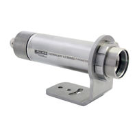
Fluke T40-LT-15-SF0-0 User Manual (97 pages)
Smart Integrated Infrared Sensors
Brand:
Fluke
| Category:
Accessories
| Size: 5.71 MB
Table of Contents
Table of Contents
1
Table of Contents
3
List of Tables
5
List of Figures
6
Compliance Statement
10
Safety Information
11
Contacts
13
1 Description
14
Figure 1-1: Available Models
15
2 Technical Data
16
Measurement Specification
16
Optical Specifications
18
Electrical Specifications
19
Model 2-Wire
19
Model 6-Wire
19
Model 12-Wire
19
Environmental Specifications
20
Dimensions
21
Model 2-Wire / 6-Wire
21
Model 12-Wire
21
Figure 2-1: Dimensions for the 2-Wire and 6-Wire Model
21
Figure 2-2: Dimensions for the 12-Wire Model
21
Scope of Delivery
22
3 Basics
23
Measurement of Infrared Temperature
23
Emissivity of Target Object
23
4 Environment
24
Ambient Temperature
24
Atmospheric Quality
24
Electrical Interference
24
Figure 4-1: One Earth Ground at the Sensor (Left) or at the Power Supply (Right)
24
Figure 4-2: Principle of the Galvanic Isolation for the 6-Wire Model
25
Figure 4-3: Principle of the Galvanic Isolation for the 12-Wire Model
25
5 Installation
26
Positioning
26
Distance to Object
26
Figure 5-1: Proper Sensor Placement
26
Viewing Angles
27
Model 2-Wire
27
Back Panel
27
Figure 5-2: Acceptable Sensor Viewing Angles
27
Figure 5-3: Rear Panel for 2-Wire Sensor
27
Cable Connection
28
Table 5-1: Terminal Connections
28
Ma Single Loop
31
Figure 5-4: Principle Circuit Diagram: Infrared Sensor with Multiple Loads
31
Table 5-2: Power Supply Requirements for Multiple Loads
32
Figure 5-5: Equivalent Circuit Diagram: Infrared Sensor with Multiple Loads
32
Ma Multiple Loops
33
Alarm Output al
33
Figure 5-6: Principle Circuit Diagram: Infrared Sensor with Multiple Loads
33
Figure 5-7: Exemplary Wiring the Alarm Output al for the 2-Wire Sensor
33
Model 6-Wire
34
Back Panel
34
Cable Connection
34
Terminal Strip
34
Analog out
34
Ma Output
34
Table 5-3: Pin Assignment for Terminal Strip
34
Figure 5-8: Rear Panel for 6-Wire Sensor
34
Output
35
TC Output
35
RS485 Communication
35
Model 12-Wire
35
Back Panel
35
Figure 5-9: Wiring Analog out as Current Output
35
Figure 5-10: Wiring Analog out as Voltage Output
35
Figure 5-11: DIN Connector Pin Layout (Pin Side)
35
RS485 Communication
36
FTC1 - Emissivity Setting
36
FTC2 - Background Temperature Compensation
36
Table 5-4: Pin Assignment for DIN Connector
36
Table 5-5: Ratio between Analog Input Voltage and Emissivity
36
Figure 5-12: Adjustment of Emissivity at FTC1 Input (Example)
36
Figure 5-13: Principle of Background Temperature Compensation
37
Trigger Input
38
Reset
38
Hold
38
Figure 5-14: Adjustment of Background Temperature Compensation at FTC2 Input (Example)
38
Figure 5-15: Wiring the Trigger Input
38
Figure 5-16: Resetting the Peak Hold Function
38
Laser
39
Relay Output
39
Analog out
39
Ma Output
39
Figure 5-17: Holding the Output Temperature
39
Figure 5-18: Spike Voltage Limitation for the Alarm Relay
39
Output
40
Figure 5-19: Wiring Analog out as Current Output
40
Figure 5-20: Wiring Analog out as Voltage Output
40
6 Rs485
41
Specification
41
Installation
41
Figure 6-1: Network in Linear Topology (Daisy Chain)
41
Wiring
42
Model 6-Wire
42
Model 12-Wire
42
Computer Interfacing
42
Figure 6-2: Wiring RS485 Communication for 6-Wire Model
42
Figure 6-3: Wiring RS485 Communication for 12-Wire Model
42
Multiple Sensors
43
Figure 6-4: Wiring the Sensor's RS485 Interface with USB/RS485 Converter in 2-Wire Mode
43
Figure 6-5: Wiring the Multiple Sensors Via RS485 Interface with USB/RS485 Converter in 2-Wire Mode
43
7 Operation
44
Laser
44
Post Processing
44
Averaging
44
Figure 7-1: Laser Indication
44
Peak Hold
45
Valley Hold
45
Figure 7-2: Averaging
45
Figure 7-3: Peak Hold
45
Advanced Peak Hold
46
Figure 7-4: Valley Hold
46
Figure 7-5: Advanced Peak Hold
46
Advanced Valley Hold
47
Advanced Peak Hold with Averaging
47
Advanced Valley Hold with Averaging
47
Figure 7-6: Advanced Peak Hold with Averaging
47
8 Accessories
48
Electrical Accessories
48
High Temp Cable 12-Wire (A-CB-HT-M16-W12-XX)
49
Table 8-6: Available Cable Lengths
49
Figure 8-1: High Temp Cable (12-Wire)
49
Low Temp Cable 12-Wire (A-CB-LT-M16-W12-XX)
51
Table 8-7: Available Cable Lengths
51
Figure 8-2: Low Temp Cable (12-Wire)
51
Terminal Block (A-T40-TB)
53
Figure 8-3: Terminal Block with Wire Color Assignment
53
Terminal Block with Enclosure (A-T40-TB-ENC)
54
Figure 8-4: Terminal Block in an Enclosure
54
Power Supply DIN Rail (A-PS-DIN-24V)
55
Figure 8-5: Industrial Power Supply
55
Power Supply with Terminal Box (A-PS-ENC-24V)
56
Figure 8-6: Power Supply with Terminal Box
56
USB/RS485 Converter (A-CONV-USB485)
57
Figure 8-7: USB/RS485 Converter
57
Mechanical Accessories
58
Figure 8-8: Overview to Mechanical Accessories
58
Figure 8-9: Mounting Nut
59
Mounting Nut (A-MN)
59
Figure 8-10: Fixed Bracket
60
Fixed Bracket (A-BR-F)
60
Adjustable Bracket (A-BR-A)
61
Figure 8-11: Adjustable Bracket
61
Figure 8-12: Swivel Bracket
62
Swivel Bracket (A-BR-S)
62
Figure 8-13: Installation of the Sighting Tube
63
Figure 8-14: Dimensions for the Sighting Tube
63
Figure 8-15: Available Sighting Tubes
63
Sighting Tube (A-ST-XX)
63
Figure 8-16: Pipe Adapter
65
Pipe Adapter (A-PA)
65
Figure 8-17: Protective Window
66
Protective Windows (A-T40-PW-XX)
66
Table 8-8: Protective Windows
66
Figure 8-18: Right Angle Mirror
67
Right Angle Mirror (A-MIR-RA)
67
Air Purge (A-AP)
68
Figure 8-19: Air Purge Collar
68
Air/Water-Cooled Housing (A-T40-WC)
69
Figure 8-20: Air/Water-Cooled Housing
69
Avoidance of Condensation
70
Table 8-9: Minimum Device Temperatures [°C/°F]
71
Figure 8-21: Thread Adapter
72
Thread Adapter (A-TA-M56)
72
Figure 8-22: Mounting Flange
73
Mounting Flange (A-MF-MOD)
73
9 Maintenance
74
Troubleshooting Minor Problems
74
Fail-Safe Operation
74
Cleaning the Lens
74
Table 9-10: Troubleshooting
74
Table 9-11: Error Codes for Analog Output
74
Table 9-12: Error Codes Via Field Bus
74
10 Programming Guide
76
Command Structure
76
Requesting a Parameter (Poll Mode)
76
Setting a Parameter (Poll Mode)
76
Sensor Response
76
Sensor Notification
76
Error Messages
76
Transfer Modes
77
Sensor Information
77
Sensor Setup
77
General Settings
77
Table 10-13: Sensor Information
77
Emissivity Setting
78
Background Temperature Compensation
78
Temperature Hold Functions
78
Table 10-14: Overview to Temperature Hold Functions
78
Sensor Control
79
Analog Output
79
Relay Output
79
RS485 Communication
79
Multidrop Mode
79
Command List
81
11 Appendix
85
Optical Diagrams
85
Models
85
Figure 11-1: Optical Diagrams LT-07 Models
85
Figure 11-2: Optical Diagrams LT-15 Models
85
Models
86
Figure 11-3: Optical Diagrams LT-30 Models
86
Models
87
Figure 11-4: Optical Diagrams LT-50 Models
87
Models
88
P7-30 Models
88
Figure 11-5: Optical Diagrams LT-70 Models
88
Figure 11-6: Optical Diagrams P7-30 Models
88
G7-70 Models
89
G5-30 Models
89
G5-70 Models
89
Figure 11-7: Optical Diagrams G7-70 Models
89
Figure 11-8: Optical Diagrams G5-30 Models
89
Figure 11-9: Optical Diagrams G5-70 Models
89
Models
90
Figure 11-10: Optical Diagrams MT-30 Models
90
Models
91
Figure 11-11: Optical Diagrams MT-70 Models
91
P3-20 Models
92
Figure 11-12: Optical Diagramsp3-20 Models
92
Models
93
Figure 11-13: Optical Diagrams HT-60 Models
93
Determination of Emissivity
94
Typical Emissivity Values
94
Advertisement
Advertisement
Related Products
Fluke T5-1000
Fluke T5-600
Fluke Thermalert 4.0 Series
Fluke TS22
Fluke TS 90
Fluke TiX620-30HZ
Fluke TB4950
Fluke TIP900
Fluke T120 VDE
Fluke TiX885
Fluke Categories
Measuring Instruments
Test Equipment
Multimeter
Thermometer
Laboratory Equipment
More Fluke Manuals
Login
Sign In
OR
Sign in with Facebook
Sign in with Google
Upload manual
Upload from disk
Upload from URL