Fluke 9040 User Manual
Phase rotation indicator
Hide thumbs
Also See for 9040:
- User manual (14 pages) ,
- User manual (16 pages) ,
- Supplement manual (9 pages)

Related Manuals for Fluke 9040


Summary of Contents for Fluke 9040
- Page 1 ® 9040/9040UK Phase Rotation Indicator Users Manual PN 2438546 April 2005 © 2005 Fluke Corporation. All rights reserved. Printed in China All product names are trademarks of their respective companies.
- Page 2 LIMITED WARRANTY AND LIMITATION OF LIABILITY This Fluke product will be free from defects in material and workmanship for one year from the date of purchase. This warranty does not cover fuses, disposable batteries, or damage from accident, neglect, misuse, alteration, contamination, or abnormal conditions of operation or handling.
-
Page 3: Table Of Contents
Table of Contents Title Page Introduction......................1 Contacting Fluke ....................1 Unpacking the 9040 .................... 2 Safety Information ....................3 Symbols....................... 5 Elements of the 9040 ..................6 Determine the Rotary Field Direction ..............7 Maintaining the 9040 ................... 8... -
Page 4: List Of Tables
List of Tables Table Title Page Symbols ....................... 5 List of Figures Figure Title Page The 9040/9040UK Phase Rotation Indicator..........6... -
Page 5: Introduction
9040/9040UK Introduction The Fluke 9040 Phase Rotation Indicator (hereafter referred to, “the 9040”) is a handheld instrument designed to detect the rotary field of three-phase systems. Contacting Fluke To contact Fluke, call one of the following telephone numbers: USA: 1-888-44-FLUKE (1-888-443-5853) -
Page 6: Unpacking The 9040
9040/9040UK Users Manual Unpacking the 9040 The 9040 ships with the following items: • 3 pieces self-retaining test probes (black) • Alligator clip • Users Manual If an item is damaged or missing, contact the place of purchase immediately. -
Page 7: Safety Information
Phase Rotation Indicator Safety Information Safety Information A WCaution identifies conditions and actions that may damage the 9040. A XWWarning identifies conditions and actions that pose hazard(s) to the user. XW Read First: Safety Information To avoid possible electric shock or fire, do the following: •... - Page 8 9040/9040UK Users Manual • When using the probes, keep fingers away from probe contacts. Keep fingers behind the finger guards on the probes. • Measurements can be adversely affected by impedances of additional operating circuits connected in parallel or by transient currents. •...
-
Page 9: Symbols
Phase Rotation Indicator Symbols Symbols The following symbols appear on the 9040 or in this manual. Table 1. Symbols Risk of electric shock Earth Risk of Danger. Important information. AC or DC See manual. Hazardous voltage. Conforms to EU directives. OVERVOLTAGE (Installation) CATEGORY III, Pollution Degree 2 per IEC1010-1 refers to the level... -
Page 10: Elements Of The 9040
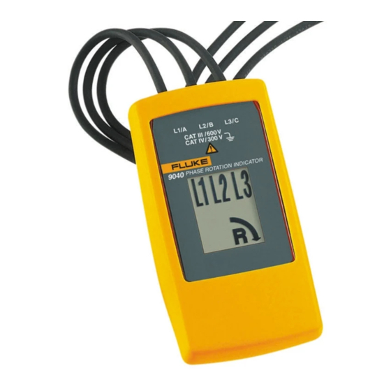
9040/9040UK Users Manual Elements of the 9040 Indicators, buttons, and jacks are shown in Figure 1. Test lead input jack L1, L2, L3 Indicators Clockwise Rotation LCD Indicator Counter-Clockwise RotationLCD Indicator Brief Instructions on instrument rear bbx02f.eps Figure 1. The 9040/9040UK Phase Rotation Indicator... -
Page 11: Determine The Rotary Field Direction
Phase Rotation Indicator Determine the Rotary Field Direction Determine the Rotary Field Direction To determine the rotary field direction: Connect the test probes to the end of the test leads. Connect the test probes to the three mains phases. The green ON indicator shows that the instrument is ready for testing. Either the clockwise or counter-clockwise rotary indicator illuminates showing the type of rotary field direction present. -
Page 12: Maintaining The 9040
9040/9040UK Users Manual Maintaining the 9040 W Caution To avoid damaging the 9040: • Do not attempt to repair or service the 9040 unless qualified to do so. • Make sure that the relevant calibration, performance test, and service information is being used. The only maintenance the 9040 requires is cleaning. -
Page 13: Specifications
Phase Rotation Indicator Specifications Protection Levels Specifications CAT III, 600 V to ground Environmental Electrical Specifications Operating Temperature 0 °C to +40 °C Power Supply From unit under test Pollution Degree Determine Rotary Field Direction Nominal Voltage Type of Protection 40 to 690 VAC IP 40 Frequency Range (f... - Page 14 9040/9040UK Users Manual...
Need help?
Do you have a question about the 9040 and is the answer not in the manual?
Questions and answers