Multitech MultiModem iCell User Manual
Hide thumbs
Also See for MultiModem iCell:
- User manual (45 pages) ,
- User manual (30 pages) ,
- Quick start manual (8 pages)
Table of Contents
Advertisement
Quick Links
Advertisement
Table of Contents

Subscribe to Our Youtube Channel
Related Manuals for Multitech MultiModem iCell


Summary of Contents for Multitech MultiModem iCell
- Page 1 ® MultiModem iCell MTCMR User Guide...
- Page 2 Legal Notices The MultiTech products are not designed, manufactured or intended for use, and should not be used, or sold or re-sold for use, in connection with applications requiring fail-safe performance or in applications where the failure of the products would reasonably be expected to result in personal injury or death, significant property damage, or serious physical or environmental damage.
-
Page 3: Table Of Contents
CONTENTS Contents Chapter 1 – Product Overview ..........................6 Overview ..................................6 Model Options ................................6 Related Documentation .............................. 6 Package Contents................................ 7 Chapter 2 – Safety Notices and Warnings ........................ 8 General Safety................................8 Radio Frequency (RF) Safety ............................8 Sécurité... - Page 4 CONTENTS MTCMR-C2 ................................29 MTCMR-C2-GP ................................30 MTCMR-E1 ................................30 MTCMR-E1-GP................................30 Powering Down Your Device (C2, H5, EV3)......................... 31 RF Specifications ................................. 31 Antenna Information..............................31 PTCRB Requirements ..............................31 HEPTA Antenna Information............................. 31 EV-DO and CDMA Antenna Information........................32 GSM/EGSM Antenna Requirements/Specifications ....................
- Page 5 CONTENTS Creating a Windows Dial-Up Connection........................45 Setting the Access Point Number (APN) in Modem's Properties ................45 Creating a Dial-up Connection in Linux........................45 Setting the Serial Baud Rate ............................45 Recovery ................................... 46 Chapter 6 – Regulatory Statements........................47 EMC, Safety, and R&TTE Directive Compliance ......................
-
Page 6: Chapter 1 - Product Overview
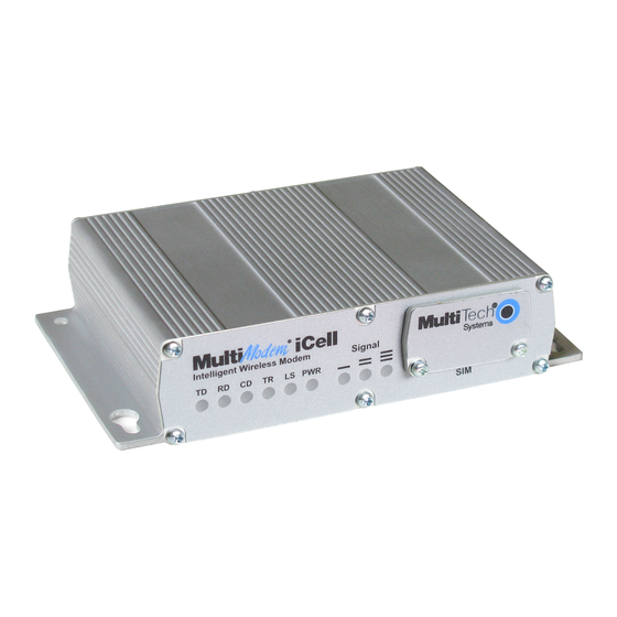
PRODUCT OVERVIEW Chapter 1 – Product Overview Overview MultiModem iCell modems provide wireless data communications and integrate seamlessly with other ® applications. MultiModem iCell includes Universal IP stack, which allows users to implement functions such as persistent connectivity and event monitoring. -
Page 7: Package Contents
PRODUCT OVERVIEW Package Contents Note: For HSPA+, EDGE, and GPRS devices, your wireless provider supplies the SIM card. Other models do not use SIM cards. Unbundled Package with No Accessories Bundled Package with Accessories 1 modem 1 modem Note: Package does not include 1 antenna (-GP builds have an additional GPS antenna) mounting screws, AC or DC power 1 RS-232 cable... -
Page 8: Chapter 2 - Safety Notices And Warnings
SAFETY NOTICES AND WARNINGS Chapter 2 – Safety Notices and Warnings General Safety The device is designed for and intended to be used in fixed and mobile applications. Fixed means the device is physically secured at one location and cannot be easily moved to another location. Mobile means the device is used in other than fixed locations. -
Page 9: Interference With Pacemakers And Other Medical Devices
SAFETY NOTICES AND WARNINGS Lors de l'installation de l'équipement dans un bâti, veillez à ce que la charge mécanique soit homogène de sorte à éviter toute situation potentiellement dangereuse. Le bâti doit supporter le poids de l'ensemble des équipements qu'il contient. Assurez-vous que le circuit d'alimentation principale est capable de gérer la charge de l'équipement. -
Page 10: User Responsibility
Do not place the device alongside computer discs, credit or travel cards, or other magnetic media. The information contained on discs or cards may be affected by the device. Using accessories, such as antennas, that MultiTech has not authorized or that are not compliant with MultiTech's accessory specifications may invalidate the warranty. -
Page 11: Chapter 3 - Leds, Connectors, And Specifications
LEDS, CONNECTORS, AND SPECIFICATIONS Chapter 3 – LEDs, Connectors, and Specifications Front MTCMR-E1, -G2, -H5 MTCMR-C1, -C2, -EV2, -EV3 LEDs Description Transmit Data: Lights when device transmits data. Not valid while in USB mode. Receive Data: Lights when device receives data. Not valid while in USB mode. Carrier Detect: Lights when there is a data connection. -
Page 12: Back
LEDS, CONNECTORS, AND SPECIFICATIONS Description OFF indicates device is OFF indicates device is turned Flashing at 75 ms on/ 75 ms off/75 turned off or not powered. off or in download mode. ms on/3 sec off indicates one or more GPRS contexts activated. -
Page 13: Mtcmr-H5 Specifications
LEDS, CONNECTORS, AND SPECIFICATIONS MTCMR-H5 Specifications Category Description General Performance HSPA+ Frequency Bands Penta band 850/900/1700/1900/2100 MHz Speed Packet Data HSDPA data service of up to 21.0 Mbps HSUPA data service of up to 5.76 Mbps Physical Description Weight 0.45 lbs. (200 g) Dimensions 3.1 in x 4.9 in x 1.1 in (7.9 cm x 12.4 cm x 2.8 cm) Connectors... -
Page 14: Mtcmr-Ev3 Specifications
LEDS, CONNECTORS, AND SPECIFICATIONS Category Description Radio Compliance FCC Part 22 FCC Part 24 RSS 132 RSS 133 EN 301 511 EN 301 489-1 EN 301 489-3 (GPS models only) EN 301 489-7 EN 301 489-24 EN 301 908 AS/ACIF S042.1, S042.3 Safety Compliance UL/cUL 60950-1 2nd Ed IEC60950-1 2nd Ed am.1... -
Page 15: Mtcmr-Ev2 Specifications
LEDS, CONNECTORS, AND SPECIFICATIONS Category Description Power 2.5mm miniature (screw-on) Type B Environment Operating Temperature -22° to 185° F (-30° to 85° C) Humidity 20%-90% relative humidity, non-condensing Power Requirements Voltage 9V to 32V DC Point-to-Point messaging Text and PDU Cell broadcast Certifications and Compliance EMC Compliance... - Page 16 LEDS, CONNECTORS, AND SPECIFICATIONS Category Description Dimensions 3.1 in x 4.9 in x 1.1 in (7.9 cm x 12.4 cm x 2.8 cm) Connectors Cellular 50 ohm SMA (female connector) RS-232 GPIO 6 pin 2x3 style Power 2.5mm miniature (screw-on) Type B Environment Operating Temperature -22°...
-
Page 17: Mtcmr-G2 Specifications
LEDS, CONNECTORS, AND SPECIFICATIONS MTCMR-G2 Specifications Category Description General Performance GPRS: Class 10 Frequency Bands Quad-band GSM/GPRS/EDGE: 850/900/1800/1900 MHz Speed Packet Data Up to 85.6K bps, coding schemes CS1 to CS4 Circuit Switched Data Up to 14.4 Kbps transparent and non-transparent Physical Description Weight 0.45 lbs. -
Page 18: Mtcmr-C1 Specifications
LEDS, CONNECTORS, AND SPECIFICATIONS Category Description Radio Compliance FCC Part 22 FCC Part 24 RSS 132 RSS 133 EN 301 511 EN 301 489-1 EN 301 489-3 (GPS models only) EN 301 489-7 EN 301 908 AS/ACIF S042.1, S042.3 Safety Compliance UL/cUL 60950-1 2nd Ed IEC60950-1 2nd Ed am.1 Network Compliance... -
Page 19: Mtcmr-C2 Specifications
LEDS, CONNECTORS, AND SPECIFICATIONS Category Description Power 2.5mm miniature (screw-on) Type B Environment Operating Temperature -40° to 185° F (-40° to 85° C) Humidity 20%-90% relative humidity, non-condensing Power Requirements Voltage 9V to 32V DC Point-to-Point messaging Text and PDU Cell broadcast Certifications and Compliance EMC Compliance... -
Page 20: Mtcmr-E1 Specifications
LEDS, CONNECTORS, AND SPECIFICATIONS Category Description Dimensions 3.1 in x 4.9 in x 1.1 in (7.9 cm x 12.4 cm x 2.8 cm) Connectors Cellular 50 ohm SMA (female connector) RS-232 GPIO 6 pin 2x3 style Power 2.5mm miniature (screw-on) Type B Environment Operating Temperature -22°... - Page 21 LEDS, CONNECTORS, AND SPECIFICATIONS Category Description Packet Data EDGE: E-GPRS Up to 240K bps, coding scheme MCS 1-9, mobile station Class B, LLC layer, 4 time slots. GPRS: Full PBCCH support, coding scheme 1-4, mobile station Class B Circuit Switched Data Up to 14.4K bps, non-transparent Physical Description Weight...
- Page 22 LEDS, CONNECTORS, AND SPECIFICATIONS Category Description Radio Compliance FCC Part 22 FCC Part 24 RSS 132 RSS 133 EN 301 511 EN 301 489-1 EN 301 489-3 (GPS models only) EN 301 489-7 EN 301 908 AS/ACIF S042.1, S042.3 Safety Compliance UL/cUL 60950-1 2nd Ed IEC60950-1 2nd Ed am.1 Network Compliance...
-
Page 23: Power Measurements
LEDS, CONNECTORS, AND SPECIFICATIONS Power Measurements Multi-Tech Systems, Inc. recommends that you incorporate a 10% buffer into your power source when determining product load. Note: Note the following: Maximum: The continuous current during maximum data rate with the radio transmitter at maximum power. -
Page 24: Mtcmr-H5-Gp
LEDS, CONNECTORS, AND SPECIFICATIONS MTCMR-H5-GP GSM 850 Idle Typical Maximum Peak TX In-rush Current 9 volts Current (AMPS) 0.097 0.125 0.225 1.32 1.63 Watts 0.895 1.150 2.070 20 volts Current (AMPS) 0.051 0.063 0.108 0.570 1.74 Watts 1.020 1.260 2.160 32 volts Current (AMPS) 0.035... -
Page 25: Mtcmr-Ev3-Gp
LEDS, CONNECTORS, AND SPECIFICATIONS Typical Maximum Peak TX In-rush Current Current (AMPS) 0.045 0.107 0.176 1.70 Watts 1.44 3.42 EV-DO Typical Maximum Peak TX In-rush Current 9 volts Current (AMPS) 0.118 0.275 0.360 2.55 Watts 1.06 2.48 20 volts Current (AMPS) 0.061 0.133 0.204... -
Page 26: Mtcmr-Ev2
LEDS, CONNECTORS, AND SPECIFICATIONS Typical Maximum Peak TX In-rush Current Current (AMPS) 0.084 0.158 0.232 1.86 Watts 1.68 3.16 32 volts Current (AMPS) 0.056 0.105 0.176 1.65 Watts 1.79 3.36 MTCMR-EV2 CDMA 2000 Sleep Typical Maximum 9 volts Current (AMPS) 0.061 0.160 0.485... -
Page 27: Mtcmr-Ev2
LEDS, CONNECTORS, AND SPECIFICATIONS MTCMR-EV2 CDMA 2000 Sleep Typical Maximum 9 volts Current (AMPS) 0.119 0.220 0.560 Watts 1.10 2.02 5.09 20 volts Current (AMPS) 0.062 0.110 0.265 Watts 1.24 2.20 5.30 32 volts Current (AMPS) 0.044 0.075 0.175 Watts 1.141 2.40 5.60... -
Page 28: Mtcmr-G2
LEDS, CONNECTORS, AND SPECIFICATIONS MTCMR-G2 Sleep Typical Maximum Peak TX 9 volts Current (AMPS) 0.069 0.109 0.194 1.53 Watts 0.640 1.010 1.790 20 volts Current (AMPS) 0.038 0.056 0.096 0.668 Watts 0.760 1.120 1.920 32 volts Current (AMPS) 0.030 0.041 0.065 0.453 Watts... -
Page 29: Mtcmr-C1-Gp
LEDS, CONNECTORS, AND SPECIFICATIONS Sleep Typical Maximum Watts 0.67 1.47 3.68 MTCMR-C1-GP Sleep Typical Maximum 9 volts Current (AMPS) 0.096 0.175 0.435 Watts 0.89 1.62 4.00 20 volts Current (AMPS) 0.052 0.092 0.205 Watts 1.04 1.84 4.10 32 volts Current (AMPS) 0.037 0.062 0.135... -
Page 30: Mtcmr-C2-Gp
LEDS, CONNECTORS, AND SPECIFICATIONS MTCMR-C2-GP Idle Typical Maximum Peak Inrush Curren 9 volts PCS (1900 MHz) Curren 0.119 0.158 0.448 0.488 2.09 (AMPS) Watts 1.10 1.46 4.10 20 volts PCS (1900 MHz) Curren 0.061 0.079 0.213 0.252 1.81 (AMPS) Watts 1.22 1.58 4.26... -
Page 31: Powering Down Your Device (C2, H5, Ev3)
LEDS, CONNECTORS, AND SPECIFICATIONS Sleep Typical Maximum Peak TX 20 volts Current (AMPS) 0.051 0.080 0.190 0.890 Watts 1.02 1.60 3.80 32 volts Current (AMPS) 0.035 0.056 0.122 0.609 Watts 1.125 1.79 3.90 Powering Down Your Device (C2, H5, EV3) CAUTION: Failing to properly shutdown the device before removing power may corrupt your device's file system. -
Page 32: Ev-Do And Cdma Antenna Information
LEDS, CONNECTORS, AND SPECIFICATIONS Multi-Tech Part Number: 45009735L MultiTech Ordering Information: Model Quantity ANHB-1HRA ANHB-10HRA ANHB-50HRA 3G Antenna Requirements/Specifications Category Description Frequency Range 824 – 960 MHz / 1710 – 1990 MHz / 1920 – 2170 MHz Impedance 50 Ohms VSWR VSWR should not exceed 2.0:1 at any point across the bands of operation... -
Page 33: Gsm/Egsm Antenna Requirements/Specifications
LEDS, CONNECTORS, AND SPECIFICATIONS EV-DO and CDMA Antenna Requirements Category Description Frequency Range 824 - 894 MHz / 1850 - 1990 MHz Impedance 50 Ohms VSWR VSWR should not exceed 2.0:1 at any point across the bands of operation Typical Radiated Gain 2 dBi on azimuth plane Radiation Omni-directional... -
Page 34: Connecting Direct Dc Power Accessories
LEDS, CONNECTORS, AND SPECIFICATIONS Category Description Accuracy Position 2.5m CEP Velocity 0.1m/sec Update Rate 1Hz standard Dynamics Open Sky TTFF Hot start 1 second Cold start 29 seconds average Reacquisition < 1s Operational Limits Altitude < 18,000m or Velocity < 515m/s Datum Default WGS-84 Interface... -
Page 35: Gpio
LEDS, CONNECTORS, AND SPECIFICATIONS GPIO GPIO Cable GPIO Connector Use Universal IP (UIP) AT Commands to configure GPIO pins. Refer to the Universal IP (UIP) AT Command Reference Guide for more information. Pin Number Description GPIO 6-pin Connector Pin 1 DIO 0 Pin 2 DIO 1... - Page 36 LEDS, CONNECTORS, AND SPECIFICATIONS Configure Pin 3 as either Digital Input (3.3V tolerant TTL/CMOS levels), Digital Output (3.3V High) or as an ADC input (0 to 3.3V rail) Configure Pin 4 as either Digital Input (3.3V tolerant TTL/CMOS levels), Digital Output (3.3V High) or as an ADC input (0 to 3.3V rail) Pin 5, ADC input (0 to 3.3V rail) Pin 6 is GND and must be connected to the ground of the attached device...
-
Page 37: Rs-232 9-Pin Female Connector
LEDS, CONNECTORS, AND SPECIFICATIONS RS-232 9-Pin Female Connector Abbreviation Description In/Out Carrier Detect Receive Transmit Data Terminal Ready Ground Data Set Ready Request to Send Clear to Send Ring Indicator ® MultiModem iCell MTCMR User Guide... -
Page 38: Chapter 4 - Device Activation And Installation
Account Activation for Cellular Devices Some MultiTech devices are pre-configured to operate on a specific cellular network. To use the device, you must set up a cellular data account with your service provider. Each service provider has its own process for adding devices to their network. -
Page 39: Removing A Sim Card
DEVICE ACTIVATION AND INSTALLATION Insert the SIM card into the card holder with the contact side facing down as shown. Verify that the SIM card fits into the holder properly and replace the cover. Removing a SIM Card To remove the SIM card: You need: Phillips screwdriver Needle-nose pliers... -
Page 40: Connecting Antennas, Cables, And Power
DEVICE ACTIVATION AND INSTALLATION Insert the latch on the blade into the notch on the power supply. Slide the lock down and hold it while you press the blade in place. Then, release it. 1 - Latch 2 - Notch 3 - Sliding lock Connecting Antennas, Cables, and Power To cable your device. -
Page 41: Installing Drivers
For Windows: The following installation procedure is compatible with 32 and 64-bit versions of Microsoft Windows 7, 8, Vista, XP, and Server 2003/2008. Note: If using Windows XP, you need Service Pack 3. Download the driver from multitech.com/support.go. Unzip the driver. For serial devices, skip to Step 5. For USB devices continue with Step 3. -
Page 42: Verifying That Modem Installed Successfully In Windows
DEVICE ACTIVATION AND INSTALLATION Select MTSMCIP_MTCMRIP.INF and click Open. Select your device from the list and click Next. Choose the COM Port your device is connected to and click Next. Click Finish to complete the install. Verifying that Modem Installed Successfully in Windows To verify that device installed correctly: In the Phone and Modem Options window, highlight your modem and click Properties. -
Page 43: Chapter 5 - Basic Operations
AT commands allow you to configure, operate, and query your device. To send AT commands, use terminal software such as HyperTerminal, TerraTerm, Kermit, or Putty. Download the AT Command Reference Guide for your model from multitech.com/support.go. Verifying Signal Strength To verify the device signal strength, enter:... -
Page 44: Example
BASIC OPERATIONS 6.4% to 12.8% More than 12.8% Not known or not detectable Note: Signal strength of 10 or higher is needed for successful packet data sessions. Example A example response to AT+CSQ: +CSQ: 15,1 Checking Network Registration Before establishing a packet data connection, verify the is device registered on the network. To do this enter the network registration report read command: AT+CREG? If the device returns:... -
Page 45: Creating A Windows Dial-Up Connection
BASIC OPERATIONS Note: For HSPA+, EDGE, and GPRS devices, setup your device's Access Point Number before creating the dial- up connections. Creating a Windows Dial-Up Connection Each version of the Windows operating system has different steps for creating dial-up Internet connections. Consult Windows Help for the specific steps for your version. -
Page 46: Recovery
BASIC OPERATIONS Open a terminal program with the following settings: 19200, 8, NONE, Hardware Flow Control When the modem boots there is a 500ms window to enter the following AT command sequence: Enter: Enter: M Response: MU Enter: D Response: M Enter: S Response: S<cr><if><OK<cr><if>... -
Page 47: Chapter 6 - Regulatory Statements
REGULATORY STATEMENTS Chapter 6 – Regulatory Statements EMC, Safety, and R&TTE Directive Compliance The CE mark is affixed to this product to confirm compliance with the following European Community Directives: Council Directive 2014/30/EU on the approximation of the laws of Member States relating to electromagnetic compatibility;... - Page 48 REGULATORY STATEMENTS Cet appareil numérique de la classe B respecte toutes les exigences du Reglement Canadien sur le matériel brouilleur. This device complies with Industry Canada license-exempt RSS standard(s). The operation is permitted for the following two conditions: the device may not cause interference, and this device must accept any interference, including interference that may cause undesired operation of the device.
-
Page 49: Chapter 7 - Environmental Notices
Substances) complements the WEEE Directive by banning the presence of specific hazardous substances in the products at the design phase. The WEEE Directive covers all MultiTech products imported into the EU as of August 13, 2005. EU-based manufacturers, distributors, retailers and importers are obliged to finance the costs of recovery from municipal collection points, reuse, and recycling of specified percentages per the WEEE requirements. -
Page 50: Restriction Of The Use Of Hazardous Substances (Rohs)
2011/65/EU of the European Parliament (Restriction of the use of certain Hazardous Substances in electrical and electronic equipment - RoHS). These MultiTech products do not contain the following banned chemicals Lead, [Pb] < 1000 PPM Mercury, [Hg] <... -
Page 51: Information On Hs/Ts Substances According To Chinese Standards
ENVIRONMENTAL NOTICES Information on HS/TS Substances According to Chinese Standards In accordance with China's Administrative Measures on the Control of Pollution Caused by Electronic Information Products (EIP) # 39, also known as China RoHS, the following information is provided regarding the names and concentration levels of Toxic Substances (TS) or Hazardous Substances (HS) which may be contained in Multi-Tech Systems Inc. -
Page 52: Information On Hs/Ts Substances According To Chinese Standards (In Chinese)
ENVIRONMENTAL NOTICES Information on HS/TS Substances According to Chinese Standards (in Chinese) 依 依 照 照 中 中 国 国 标 标 准 准 的 的 有 有 毒 毒 有 有 害 害 物 物 质 质 信 信 息 息 根据中华人民共和国信息产业部... -
Page 53: Index
INDEX Index Access Point Number ..........44 45 EGSM account activation............38 antenna requirements ..........33 activation cellular devices............38 specifications ............15 antenna .................33 CDMA ...............32 specifications ............14 19 connecting ...............40 EV-DO EV-DO...............32 antenna..............32 FCC ................33 HSPA+...............31 APN................44 45 antenna requirements ..........33 FCC Notice back panel ..............12 Class B ..............47 baud rate...............45... - Page 54 INDEX PTCRB ................31 LED ................11 Linux ................45 radio frequency interference..........8 remove SIM card ..............39 maintenance ..............10 RF specifications............31 maximum current ............23 RoHS................50 modem RS-232 ................37 safety .................8 connector..............12 MTCMR-C1 ...............18 28 MTCMR-C1-GP ..............29 MTCMR-E1 ...............20 30 MTCMR-E1-GP...............30 safety MTCMR-EV2 ............26 29 30 modem...............8 MTCMR-EV2-GP ............27 RF interference ............8...
- Page 55 INDEX USB cable ..............40 user responsibility............10 vehicle power............34 40 vehicle safety ..............9 verify device setup.............42 ® MultiModem iCell MTCMR User Guide...
Need help?
Do you have a question about the MultiModem iCell and is the answer not in the manual?
Questions and answers