Enwork Equilibrium Installation Instruction
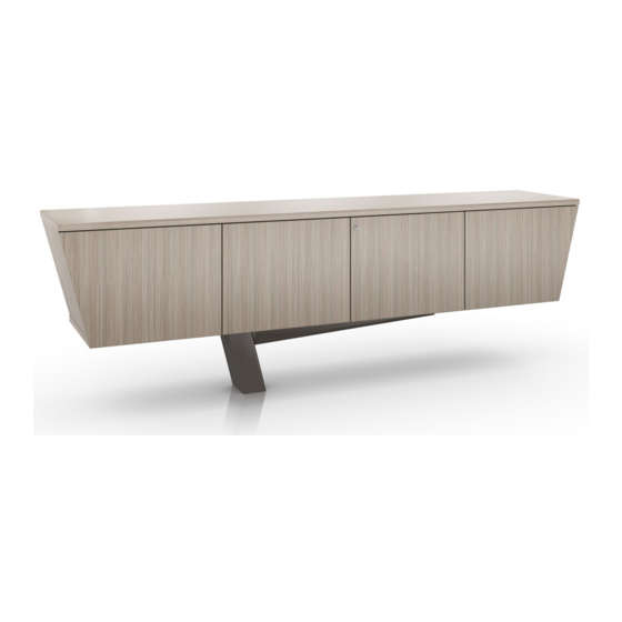
Cantilevered base & tapered credenza
Hide thumbs
Also See for Equilibrium:
- Installation instruction (19 pages) ,
- Installation manual (5 pages)

Related Manuals for Enwork Equilibrium


Summary of Contents for Enwork Equilibrium
- Page 1 Equilibrium Credenza Cantilevered base & Tapered Credenza Installation Instruction EI0006 – Revision A – 8/20/18...
- Page 2 0.167 square foot area. It is the responsibility of the dealer to verify that the location for Equilibrium is suitable and is properly installed. End user agrees that the installation shall not be modified and the location of the table base shall not be moved without assistance from an Enwork Dealer.
-
Page 3: Tools And Supplies Required
INSTALLATION GUIDE 1) Tools and Supplies Required ½” Diameter Drill / Hammer Drill Tape Measure 3/4” Socket Masonry Drill Bit Square Drive Marker Socket Wrench Adjustable Wrench Vacuum Utility Knife Roll of Tape Hammer or Mallet Level... - Page 4 INSTALLATION GUIDE 2) Parts and Fasteners Included ½” x 3 ¾” Concrete Stud Aluminum Shim (Pack) Screw 1 (Black)
- Page 5 INSTALLATION GUIDE 2) Parts and Fasteners Included Credenza Base Tapered Credenza EQM-2242 EQL-2099-xxxx Removable cover EQM-1599...
- Page 6 INSTALLATION GUIDE 3) Assembly: Installing the Base Fig. 3...
- Page 7 INSTALLATION GUIDE 3) Assembly: 3.1.1) Locate final location of base 3.1.2) Using credenza base, trace hole location for base placement and carpet removal Fig. 3.1 3.2.1) Set base over marked hole locations. Note: Check that base is oriented as desired 3.2.2) Using a utility knife, cut away any carpet around the base location 3.2.3) With carpet removed, double-check hole...
- Page 8 INSTALLATION GUIDE 3) Assembly: 3.4.1) Drill marked hole locations to 2 ¾” deep. 3.4.2) Vacuum out the drilled holes to remove dust that may prevent anchor from seating properly. Fig. 3.4 3.5.1) Place one washer and one hex nut onto provided concrete anchor so that the hex nut is flush with the top of the anchor.
- Page 9 INSTALLATION GUIDE 3) Assembly: Fig. 4...
- Page 10 INSTALLATION GUIDE Installing Credenza continued 3) Assembly: Fig. 4.2 Fig. 4.1 4.1.1) Place Credenza onto base 4.2.1) Center credenza on the base, measuring from the front, back, and sides of the credenza to the top mounting plate of base. Fig. 4.3 Fig.
- Page 11 INSTALLATION GUIDE Installing Credenza continued 3) Assembly: Fig. 5.1 Fig. 5.2 5.2.1) Install the base cover by attaching it to 5.1.1) If power routing is needed, refer to pre-installed magnets diagram above for routing through the base. 5.2.2) Fig. 5.2 shows power routing hole up for 5.1.2) Once power cord is routed through base, no power option secure credenza to base using screw 1...
- Page 12 12900 Christopher Drive Lowell, MI 49331 800.815.7251 www.enwork.com Specifications subject to change without notice.
Need help?
Do you have a question about the Equilibrium and is the answer not in the manual?
Questions and answers