
Related Manuals for Enwork Sliding Top Desk


Summary of Contents for Enwork Sliding Top Desk
- Page 1 Sliding Top Desk Sliding Top Desk AMI0004 - Installation Instruction Revision A 12/14/2017...
- Page 2 INSTALLATION GUIDE 1) Parts and Fasteners Included AMM-3030-xx QTY: (1) LVTER QTY: (2) EM-2162-3 QTY: (2) BOLTED FRAME ASSEMBLY LEG COLUMN ASSEMBLY FOOT WELDMENT AMM-1424-xx QTY: (1) AMM-1425-2 QTY: (1) AMM-1433-2 QTY: (4) TROUGH WIRE MANAGEMENT COVER SLIDING/STOP BRACKET AML-1355-xx QTY: (1) AML-1354-xx QTY: (1) FOOT ATTACHMENT QTY: (2) SPACER...
- Page 3 INSTALLATION GUIDE 1) Parts and Fasteners Included 3M BUMPON ADHESIVE M6 X 16mm SHCS #8-32 x .375” MACHINE SCREW BACKED RUBBER BUMPER QTY: (20) QTY: (11) QTY: (2) #10 x 2.25” WOOD SCREW #8 x 0.75” PAN HEAD WOOD SCREW #8x 0.75”...
-
Page 4: Tools And Supplies Required
INSTALLATION GUIDE 2) Tools and Supplies Required DRILL / DRIVER RIGHT ANGLE DRILL ADAPTER #2 PHILLIPS DRIVER BIT 5mm HEX BIT... -
Page 5: Assembly Overview
INSTALLATION GUIDE 3) Assembly Overview 1. Surface preparation 2. Bolted frame attachment 3. Leg column attachment 4. Slide-stop bracket attachment 5. Trough attachment FIGURE 3.1 WORKSURFACE 6. Foot attachment 7. Handset Attachment 8. Wire Management 9. Completed Table FIGURE 3.3 BOLTED FRAME ATTACHMENT FIGURE 3.6 LEG AND FOOT ATTACHMENT... -
Page 6: Exploded View
INSTALLATION GUIDE Exploded View 4) Assembly: FIGURE 4.0.1 EXPLODED ASSEMBLY VIEW... - Page 7 INSTALLATION GUIDE 4) Assembly: Bolted Frame Attachment Figure 4.2.1 FIGURE 4.1.1 Work-surface preparation Bolted frame attachment Place both work-surface pieces (AML-1354-xx Line up the predrills of the work-surface back and AML-1355-xx) down on a padded piece (AML-1354-xx) to the through holes of workbench or similar non-marring surface.
- Page 8 INSTALLATION GUIDE Bolted Frame Attachment Cont. 4) Assembly: Open the drawer slides (6500B 14) and line up the predrills to the circular holes in the drawer slide. Attach the drawer slides to the work-surface sliding piece (AML-1355-xx) using (8) #8 x 0.75” Pan head wood screws.
- Page 9 INSTALLATION GUIDE Leg Column Attachment 4) Assembly: Figure 4.3.1 To attach the leg columns to the bolted frame, insert (2) M6 x 16mm socket head cap screws into the threaded holes in the back of the leg column. Do not fully drive these screws in, simply get them started into the threaded holes.
- Page 10 INSTALLATION GUIDE Leg Column Attachment Cont. 4) Assembly: Detailed view of previous step shown. The bolts will rest in the open slot cuts of the Bolted Frame assembly. Figure 4.3.2 Line up the clearance holes in the bolted frame with the threaded holes in the side of the leg column.
- Page 11 INSTALLATION GUIDE Slide-Stop Bracket Attachment 4) Assembly: Locate the two slide stop brackets (AMM-1433-2) that do not have magnets attached to them. Locate (4) #8 x 0.75” flat head wood screws. Figure 4.4.1 Attach the slide stop bracket to the designated pockets routed into the front work surface using (2) #8 x 0.75”...
- Page 12 INSTALLATION GUIDE Slide-Stop Bracket Attachment Cont. 4) Assembly: Locate (2) Slide-stop brackets with the magnets attached and (4) #8 x 0.75” Pan head wood screws. Confirm that the sliding top is in the closed position. Figure 4.4.4 Place the Slide-stop bracket on the work surface and align the clearance slots with the pre-drilled holes in the work surface.
- Page 13 INSTALLATION GUIDE Trough Attachment 4) Assembly: Figure 4.5.1 Locate the wire management trough (AMM-1424-xx). Align the clearance holes in the trough with the threaded holes in the Bolted Frame assembly. The larger clearance holes will also align with the heads of the screws from Figure 4.2.2 Attach the Trough with (7) 8-32 x 0.375”...
- Page 14 INSTALLATION GUIDE Foot Weldment Attachment 4) Assembly: Figure 4.6.1 Locate the Foot Attachment Spacer. Place the Foot Attachment Spacer on the bottom of the Leg column. Align the 4 holes in the Foot Spacer with the tapped holes in the Leg column. Locate the Foot Weldment (EM-2162-3) Align the clearance holes in the Foot Weldment to the clearance holes in the Attachment Spacer.
- Page 15 INSTALLATION GUIDE Handset Attachment 4) Assembly: Locate the electronics included with the Leg columns (LVTER). Refer to the assembly instructions included in the Leg Column box for information on assembling the electronics of the base. Figure 4.7.1 Once the electronics are properly assembled, place the power supply block in between the crossbars of the Bolted Frame assembly.
- Page 16 INSTALLATION GUIDE Wire Management Cover Attachment 4) Assembly: Locate the Wire Management Cover (AMM-1424-x) and (4) 8-32 x 0.375” pan head machine screws. Figure 4.8.1 Align the clearance holes in the Wire Management Cover with the tapped holes in the Bolted Frame assembly Attach the Wire Management Cover with (4) 8-32 x 0.375”...
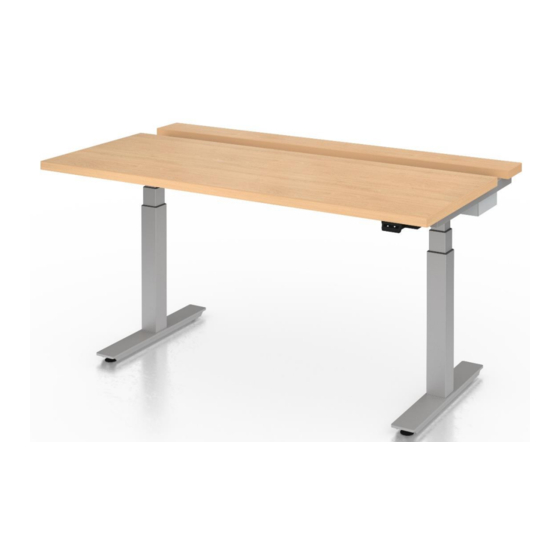
- Page 17 INSTALLATION GUIDE Completed Table 4) Assembly: FIGURE 4.9.1 Carefully flip the desk over onto the feet. Adjust the glides as needed to level the desk.
- Page 18 12900 Christopher Drive Lowell, MI 49331 800.815.7251 www.enwork.com Specifications subject to change without notice.
Need help?
Do you have a question about the Sliding Top Desk and is the answer not in the manual?
Questions and answers