Table of Contents
Advertisement
Quick Links
Advertisement
Table of Contents

Related Manuals for KanexPro SW-VDYWALL


Summary of Contents for KanexPro SW-VDYWALL
- Page 1 SW-VDYWA LL SW -VDYWA LL...
-
Page 2: Table Of Contents
SW-VDYWA LL Table of Contents Introduction ....................................4 Introduction to SW-VDYWALL ............................4 Package Contents ................................4 Specification ....................................4 Rear Panel and Connection ................................5 Rear panel introduction ..............................5 ... - Page 3 SW-VDYWA LL Diagram of Video Wall Displaying ........................... 24 Diagram of Multi-Viewer Displaying ..........................26 Diagram of Full Images Displaying ..........................27 Firmware Upgrade ..................................29 Troubleshooting & Maintenance ..............................30 ...
-
Page 4: Introduction
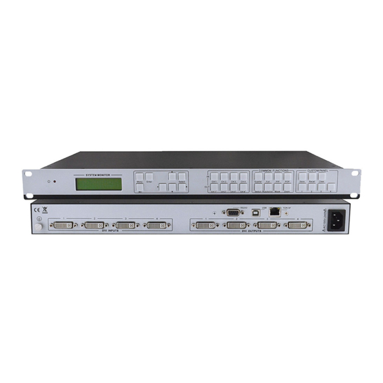
1.1 Introduction to SW-VDYWALL The KanexPro SW-VDYWALL is a Video Processor with 4 DVI input and 4 DVI output, which enables you to configure to either a 2x2 Video Wall or create a 4x1 Multi-viewer. This high-performance processor supports image overlapping and output scaling function to your specific needs. -
Page 5: Rear Panel And Connection
3.2 Connection with RS232 Communication Port With the RS232 port, the processing switchers can be control by the control software SW-VDYWALL. This RS232 communication port is a female 9-pin D connector. The definition of its pins is as the table below. - Page 6 SW-VDYWA LL 1) Use a RS232 cable to connect the COM port of the computer to the RS232 connector of SW-VDYWALL. Figure 3-3 Connecting to a PC 2) Run the control software and select RS232 connection. 3) If connection is OK, then we can control the SW-VDYWALL.
-
Page 7: Connection With Usb Interface
By connecting the USB interface between the switcher and the computer, user can control SW-VDYWALL through its USB interface. Before controlling, please install the USB driver and the control software SW-VDYWALL in the controlling computer, and check if it is well connected. Plug and play and hot plug function are supported by the USB interface of SW-VDYWALL. -
Page 8: Operations Of The Menu Buttons
SW-VDYWA LL of them, uses without selection confirmation. 3) The priority of the buttons of different menu levels is showed in 4.6 Menu Levels Introduction. Below are the detailed introductions for every button. 4.2 Operations of the Menu Buttons Buttons Operation Description Switch cyclically between the menu items in the same level. -
Page 9: Operations Of The Customized Buttons And The Numeric Keys
SW-VDYWA LL Picture outside picture (POP) displaying, 5 default modes in total. Select the input channels or the output channels, it is available together with the input channel buttons or Switch the output channel buttons when use. Resolution Set the output resolution, supports 1080P, 720P, WUXGA, UXGA, SXGA, and XGA. Adjust the position of the image, it is available together with the direction buttons (up, down, left and right) Move when use. - Page 10 SW-VDYWA LL First Level Second Level Third Level MENU Color MENU OUT 1 Brightness 0512 Contrast MENU FULL Channel Switch Type 1 IN 1 OUT 1 MENU Resolution 1 1920X1080 MENU Adjust windows Fine-tuning. MENU Channel MENU MENU Color MENU OUT 1 Brightness 0512 Contrast...
-
Page 11: Operations Of The Software
Ways for Software Control: SW-VDYWALL provides three ways for control, includes RS232 serial port, USB interface and TCP/IP network port. Software Activation: We can control SW-VDYWALL if any of connections is connected and it is the key point to activate the software. -
Page 12: Main Interface
SW-VDYWA LL l RS232 If connected successfully, the message window on the right corner of the main interface will show the message Connection Success. If not, a popup window will appear with the message can’t open com. l USB If not well connected, a popup window will appear with the message can’t Find USB. If connected, the message window will show the message Connection Success. -
Page 13: Connection Button
Factory Reset is to clear the system stored information and it will display in 4x full screen zoom-in mode. 5.3.4 Help Button Function: Check the version of the software and the firmware of SW-VDYWALL. Detailed operations: Click the sub menu About Soft Version to check the version of the software or the firmware. As shown in Figure 5-5. -
Page 14: Matrix Switching Function (Full Displaying)
5.4.4 Picture in Picture (PIP) Displaying Function: SW-VDYWALL is able to present all the input images of the four channels on a single screen. It means that while the screen is showing the main video, any of the other three input images (Had been compressed) also can be showed on this screen. - Page 15 SW-VDYWA LL Figure 5-7 The First PIP Display Effect From input 1, bottom layer. From input 2 From input 3 From input 4 Button Figure 5-8 The Second PIP Display Effect From input 2 From input 1, From input 3 bottom Layer From input 4 Button...
-
Page 16: Picture Outside Picture (Pop) Displaying
SW-VDYWA LL 5.4.5 Picture outside Picture (POP) Displaying Function: To show the output images of different channels on a single screen. It means that while the screen is showing the frame of the main video, any of the other three input images (Had been compressed) also can be showed on this screen, but locate beside the main image. -
Page 17: Additional Function Settings
SW-VDYWA LL 5.5 Additional Function Settings 5.5.1 Settings in the Auxiliary Function Area l The First Auxiliary Function Area In this area, users can set the contrast, the brightness, add or remove the border of the output images. As shown in Figure 5-15. Figure 5-15 The First Auxiliary Function Area Contrast/Brightness Setting: When you need to set the image contrast/brightness of a single channel or all channels, just select the corresponding radio button and drag the slider on the slider bar to an appropriate position. - Page 18 SW-VDYWA LL l The Second Auxiliary Function Area In this area, users can set the image position and zoom. As shown in Figure 5-16. Figure 5-16 The Second Auxiliary Function Area Image Position Setting: When you need to move the position of the output image of any single channel, just select the corresponding radio button and use the directional buttons Up, Down, Left and Right to an appropriate position.
- Page 19 SW-VDYWA LL Figure 5-17 The Third Auxiliary Function Area When in 3x zoom-in mode and 4x zoom-in mode, press the button Get to get the bezel information of the image. Enter into a new value and press the button Set to confirm. Figure 5-18 and Figure 5-19 will show you the difference between the original image and the image adjusted.
-
Page 20: Settings In The Function Area On The Main Panel
And then press the button Set to confirm. The default resolution is 1080P (1920*1080). l Input Channel Setting SW-VDYWALL supports to assign one input image to one output channel (not the physical output interface connected with the displayer). -
Page 21: Advanced Function Settings
Overlay Hierarchical Relationship Setting Overlay Hierarchical setting in SW-VDYWALL is applied for PIP display mode. In the following picture Figure 5-22, L1 (Level 1) is the bottom layer, and L4 (Level 4) is the top layer. The operation area is at the bottom of the main interface. The radio button All is for setting on all channels and Different is for setting on a single channel. - Page 22 SW-VDYWA LL Among them, the item Load mode is to load a saved or default display mode file (switch to another display mode). Save mode is to save the present mode as a new one, which is modified base on a default mode. Figure 5-26 will show you the page of Load mode. Figure 5-26 Page of Lode mode The corresponding display mode to each number is showed in following table.
-
Page 23: Shortcut Button Customization
5.6.2 Shortcut Button Customization With the shortcut buttons, SW-VDYWALL can switch quickly to a customized display mode. The operation area is showed in Figure 5-27. Figure 5-27 Shortcut Button on the Main Interface User can set this in Mode setting: select a saved mode and press the button Set Shortcut Button, it will pop up a window to set the shortcut button. -
Page 24: System Diagram
The system diagrams of the application occasions are showed as below. 6.1 Diagram of Video Wall Displaying 4x Zoom-in: It means SW-VDYWALL is able to zoom in the input image and spilt to 4 parts, and then full-screen display on the output displayers one to one. - Page 25 SW-VDYWA LL 3x Zoom-in: There will be no output image on the first output channel (the displayer just shows a blue screen), and the images on the second, third and fourth displayers (rotated 90 degrees) make up a whole image same as the input image. Figure 6-2 Diagram of 3x Zoom-in Displaying...
-
Page 26: Diagram Of Multi-Viewer Displaying
SW-VDYWA LL 6.2 Diagram of Multi-Viewer Displaying Multi-Viewer: It means SW-VDYWALL is able to display multi-channel output images on a single displayer. And it supports several displaying effects, such as PIP, POP etc. Figure 6-3 Diagram of Multi-Viewer Displaying... -
Page 27: Diagram Of Full Images Displaying
SW-VDYWA LL 6.3 Diagram of Full Images Displaying Matrix switching: With four input ports and four output ports, SW-VDYWALL is able to display any inputs to any outputs. Figure 6-4 Diagram of Matrix Switching... - Page 28 SW-VDYWA LL Distribution display: All output images are the same and also the same as the image of one input channel. Figure 6-5 Diagram of Distribution Displaying...
-
Page 29: Firmware Upgrade
7. Firmware Upgrade To meet with the request of different users or add function in future, the firmware of SW-VDYWALL can be upgraded via USB. When you need to upgrade it, first copy the update EXE file to the PC in controlled and double chick the program to execute the following operations. -
Page 30: Troubleshooting & Maintenance
SW-VDYWA LL 8. Troubleshooting & Maintenance 1) When images of terminal unit output with ghost, such as the projector output with ghost. Generally this is not an issue with the unit, an incorrect setting on the projector or a bad quality of cable may cause this. Please check the projector’s setting or try another high quality connection cable. -
Page 31: Warranty
KanexPro has been advised of the possibility of such damages.
Need help?
Do you have a question about the SW-VDYWALL and is the answer not in the manual?
Questions and answers