Advertisement
Available languages
Available languages
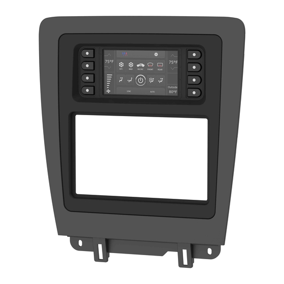
KIT COMPONENTS
• A) Radio/Display trim panel • B) Radio/Display sub-trim panel upper (a) • C) Radio/Display sub-trim panel lower (b) • D) Radio brackets upper (a)
• E) Radio brackets lower (b) • F) Pocket • G) (4) Panel clips • H) (12) #6 x 3/8" Phillips pan-head screws • I) (8) #8 x 3/8" Phillips truss-head screws
• J) Touchscreen display assembly and wiring harness • K) Antenna adapter (not shown)
A
B
The World's best kits.
®
Ford Mustang
KIT FEATURES
• ISO DIN radio provision with pocket
• ISO DDIN radio provision
• Painted charcoal with a matte black center
• Touchscreen interface for climate and
personalization features
C
D
H
metraonline.com
2010-2014
E
F
I
J
© COPYRIGHT 2018 METRA ELECTRONICS CORPORATION
99-5839CH
I N S TA L L AT I O N I N S T R U C T I O N S
TABLE OF CONTENTS
Dash Disassembly ..................................................2
Kit Preparation .......................................................3
-ISO DIN radio provision with pocket ..................4
-ISO DDIN radio provision .....................................5
Axxess Interface Installation .............................6-11
WIRING & ANTENNA CONNECTIONS
Wiring Harness: Axxess interface and wiring
harness included
Antenna Adapter: Included
TOOLS REQUIRED
G
• Panel removal tool • Phillips screwdriver
• 9/32" Socket wrench
CAUTION!
All accessories, switches, climate
controls panels, and especially air bag indicator
lights must be connected before cycling the
ignition. Also, do not remove the factory radio
with the key in the on position, or while the
vehicle is running.
REV. 5/4/18 INST99-5839CH
Advertisement
Chapters

Related Manuals for Metra Electronics 99-5839CH


Summary of Contents for Metra Electronics 99-5839CH
-
Page 1: Table Of Contents
Also, do not remove the factory radio with the key in the on position, or while the vehicle is running. The World’s best kits. metraonline.com ® © COPYRIGHT 2018 METRA ELECTRONICS CORPORATION REV. 5/4/18 INST99-5839CH... -
Page 2: Dash Disassembly
DASH DISASSEMBLY 1. Unclip and remove the trim panel surrounding the shifter including the cup holders. (Figure A) 2. Remove the (2) 9/32” screws from the bottom of the radio/climate control panel, and then unclip and remove the panel. (Figure B) 3. -
Page 3: Kit Preparation
KIT PREPARATION 1. There are two different radio/display 2. Attach the desired radio/display sub- sub-trim panels to choose from. One for trim panel to the radio/display panel mounting the radio in the upper portion using the (12) #6 x 3/8” pan-head of the kit, and another one for mounting screws provided. -
Page 4: Kit Assembly
KIT ASSEMBLY ISO DIN radio provision with pocket Attach the pocket to the appropriate radio brackets using the (4) #8 x 3/8” Phillips truss-head screws provided. (Figure A) Remove the metal DIN sleeve and trim ring from the aftermarket radio. Slide the radio into the bracket/pocket assembly, and then secure it using the screws supplied with the radio. -
Page 5: Iso Ddin Radio Provision
KIT ASSEMBLY ISO DDIN radio provision Attach the appropriate radio brackets to the radio using the screws supplied with the radio. (Figure A) Continue to Axxess Interface Installation (Figure A) REV. 5/4/2018 INST99-5839CH... -
Page 6: Axxess Interface Installation
AXXESS INTERFACE INSTALLATION CONNECTIONS TO BE MADE INTERFACE FEATURES From the 16-pin harness with stripped leads to the aftermarket radio: • Provides accessory power (12-volt 10-amp) • Connect the Red wire to the accessory wire. • Retains R.A.P. (retained accessory power) •... - Page 7 CONNECTIONS TO BE MADE (CONT.) From the 5839 harness to the aftermarket radio: 4-pin harness with yellow RCA jacks: This harness is to be used to add an aftermarket backup camera to the touchscreen display, • Connect the Black wire to the ground wire. if so desired.
- Page 8 CONNECTIONS TO BE MADE INSTALLING THE INTERFACE (CONT.) 3.5mm jack steering wheel control retention: With the key in the off position: • The 3.5mm jack is to be used to retain audio controls on the steering wheel control. 1. Connect the 16-pin harness with stripped leads into port “B” in the touchscreen display.
- Page 9 Attention! If the interface loses power for any reason, the following steps will need to be SYNC: performed again. If the vehicle is equipped with SYNC, the 99-5839CH can retain this feature. 1. Turn the key to the ignition position and wait until the radio comes on. 1. Change the source of the radio to AUX-IN.
- Page 10 TOUCHSCREEN DISPLAY OPERATION HVAC screen Heated/Cooled seats screen • This is the HVAC control screen which will be displayed on the touchscreen display. This is Auto Climate: The climate controls will function in the same manner that they did with the considered the main screen.
- Page 11 TOUCHSCREEN DISPLAY OPERATION (CONT.) Configuration Settings screen • Steering Wheel Controls • Remap Buttons – For remapping the steering wheel control buttons • Dual Assign – For dual assigning the steering wheel control buttons (long button press) • Select Radio – For auto detecting the radio, or changing the radio type •...
- Page 12 STEERING WHEEL CONTROL SETTINGS Select Radio screen * Note: If the interface shows an Alpine radio, and you do not have an Alpine radio, that means the interface does not detect a radio connected it, i.e., an open connection. Verify that the 3.5mm jack is connected to the correct steering wheel jack/wire in the radio.
- Page 13 STEERING WHEEL CONTROL SETTINGS (CONT.) Remap Button screen Dual Assign screen • The interface has the ability to change the button assignment for the steering wheel • The interface has the capability to assign two functions to a single button, except Volume- control audio buttons, except Volume-Up and Volume-Down.
- Page 14 1.800.221.0932 MetraOnline.com...
- Page 15 REV. 5/4/2018 INST99-5839CH...
- Page 16 Log onto www.installerinstitute.com or call 800-354-6782 for more information and take steps toward a better tomorrow. Metra recommends MECP certified technicians The World’s best kits. metraonline.com ® © COPYRIGHT 2018 METRA ELECTRONICS CORPORATION REV. 5/4/18 INST99-5839CH...
- Page 17 Además, no quite el radio de fábrica con la llave en la posición o de encendido ni con el vehículo funcionando. The World’s best kits. MetraOnline.com ® © COPYRIGHT 2018 METRA ELECTRONICS CORPORATION REV. 5/4/18 INST99-5839CH...
-
Page 18: Desmontaje Del Tablero
DESMONTAJE DEL TABLERO 1. Desenganche y retire el panel de moldura que rodea la palanca de velocidades, incluyendo los portavasos. (Figura A) 2. Quite los (2) tornillos de 9/32” de la parte inferior del panel del radio/control del clima, y luego desenganche y quite el panel. -
Page 19: Preparación Del Kit
PREPARACIÓN DEL KIT 1. Hay dos paneles de la sub moldura 2. Sujete el panel de la sub moldura del del radio/pantalla diferentes de dónde radio/pantalla deseado al panel del escoger. Uno para montar el radio en radio/pantalla, usando los (12) tornillos la porción superior del kit y otro para #6 de 3/8”... -
Page 20: Ensamble Del Kit
ENSAMBLE DEL KIT Provisión de radio ISO DIN con cavidad 1. Sujete la cavidad a los soportes del radio apropiados usando los (4) tornillos Phillips #8 de 3/8” de cabeza segmentada suministrados. (Figura A) 2. Quite la manga de metal DIN y el anillo de moldura del radio de mercado secundario. -
Page 21: Provisión De Radio Iso Ddin
ENSAMBLE DEL KIT Provisión de radio ISO DDIN Sujete los soportes al radio apropiados al radio usando los tornillos suministrados con el radio. (Figura A) Continúe con la instalación de la interfaz Axxess (Figura A) REV. 5/4/2018 INST99-5839CH... -
Page 22: Instalación De La Interfase Axxess
INSTALACIÓN DE LA INTERFASE AXXESS CONEXIONES QUE SE DEBEN HACER CARACTERÍSTICAS DE LA INTERFAZ Del arnés de 16 pins con conectores pelados al radio de mercado secundario: • Provee corriente de accesorio (12 voltios 10 amperes) • Conecte el cable rojo al cable de accesorios. •... - Page 23 CONEXIONES QUE SE DEBEN HACER (CONT.) Desde el arnés 5839 al radio de mercado secundario: Arnés de 4 pins con conectores RCA amarillos: • Conecte el cable negro al cable de tierra. Este arnés debe usarse para agregar una cámara de reversa de mercado secundario a la pantalla táctil, si así...
- Page 24 CONEXIONES QUE SE DEBEN HACER INSTALACIÓN DE LA INTERFAZ (CONT.) La retención del control en volante con conector de 3.5 mm Con la llave en la posición de apagado: • El conector de 3.5 mm se debe usar para retener los controles de audio en el control del volante. 1.
- Page 25 ¡Atención! Si la interfaz pierde la alimentación por cualquier motivo, deberá realizar los SYNC: siguientes pasos de nuevo. Además, si va a instalar un ASWC-1, conéctelo después de inicializar Si el vehículo está equipado con SYNC, el 99-5839CH puede conservar esta función. y probar la interfaz/radio con la llave en la posición de apagado. • Cambie la fuente del radio a AUX-IN. 1. Gire la llave a la posición de encendido y espere a que se encienda el radio.
- Page 26 OPERACIÓN DE LA PANTALLA TÁCTIL Pantalla de control HVAC Pantalla de asientos con calefacción/enfriamiento • Esta es la pantalla de control HVAC que se mostrará en la pantalla táctil. Esto se considera la Modelos automáticos de clima: Los controles del clima funcionarán del mismo modo que con los pantalla principal.
- Page 27 OPERACIÓN DE LA PANTALLA TÁCTIL (CONT.) Pantalla de Configuraciones • Controles en el volante • Botones de reubicación: para reubicar los botones del control en el volante • Doble asignación: para doble asignación de los botones de control en el volante (presionar el botón por largo tiempo) •...
- Page 28 CONFIGURACIÓN DEL CONTROL EN EL VOLANTE Seleccionar la pantalla del radio * Nota: Si la interfaz muestra un radio Alpine y no tiene un radio Alpine, eso significa que la interfaz no detecta un radio conectado a él; es decir, una conexión abierta. Verifique que el conector de 3.5 mm esté conectado al conector/cable correcto del volante en el radio. ** Nota: Se requiere el AX-SWC-PARROT (se vende por separado). Además, el radio Parrot debe estar actualizado a la versión de software 2.1.4 o posterior mediante www.parrot.com. † Nota: Si tiene un radio Clarion y los controles en el volante no funcionan, cambie el tipo de radio al otro tipo de radio Clarion; haga lo mismo con Eclipse. ‡ Nota: Si tiene un radio Kenwood y la pantalla táctil muestra un radio JVC, cambie el tipo de radio a Kenwood. • Para mostrar qué marca de radio se “detecta automáticamente” a la interfaz, oprima el Continua en la siguiente pagina botón “Autodetect”.
- Page 29 CONFIGURACIÓN DE CONTROL EN VOLANTE (CONT.) Pantalla para reubicar el botón Pantalla de doble asignación • La interfaz tiene la capacidad de cambiar la asignación de botón para los botones de audio del • La interfaz tiene la capacidad de asignar dos funciones a un solo botón, excepto Subir control en el volante, excepto para Subir volumen y Bajar volumen.
- Page 30 1.800.221.0932 MetraOnline.com...
- Page 31 REV. 5/4/2018 INST99-5839CH...
- Page 32 800-354-6782 for more information and take steps www.installerinstitute.com o llame al toward a better tomorrow. 800-354-6782 para obtener más información y avance hacia un futuro mejor. Metra recomienda MECP Técnicos certificados The World’s best kits. MetraOnline.com ® © COPYRIGHT 2018 METRA ELECTRONICS CORPORATION REV. 5/4/18 INST99-5839CH...
Need help?
Do you have a question about the 99-5839CH and is the answer not in the manual?
Questions and answers