Advertisement
Quick Links
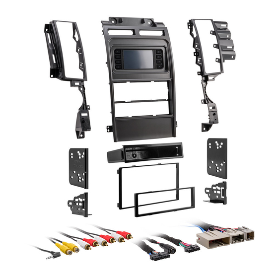
KIT COMPONENTS
• A) Radio trim panel with touchscreen display • B) A/C vent trim panels • C) ISO DDIN brackets • D) ISO DDIN trim plate • E) ISO DIN brackets
• F) ISO DIN trim plate • G) Pocket • H) (10) #8 x 3/8" Phillips screws
A
B
The World's best kits.
®
Ford Taurus*
* Only for models with a key start
KIT FEATURES
• DIN radio provision with pocket
• ISO DIN radio provision with pocket
• ISO DDIN radio provision
• Painted silver
• Touchscreen display for climate and personalization features
C
D
G
2010-2012
E
F
H
99-5722
I N S TA L L AT I O N I N S T R U C T I O N S
TABLE OF CONTENTS
Dash Disassembly ...............................................2-3
Kit Preparation .......................................................4
Kit Assembly
–DIN radio provision with pocket ........................5
–ISO DIN radio provision with pocket ..................6
–ISO DDIN radio provision .....................................7
Axxess Interface Installation ............................8-16
WIRING & ANTENNA CONNECTIONS (sold separately)
Wiring Harness: Axxess interface
and harness included
Antenna Adapter: 40-EU10 (sold separately)
TOOLS REQUIRED
• Panel removal tool • Phillips screwdriver
• 9/32" socket wrench • Cutting tool
CAUTION!
All accessories, switches, climate
controls panels, and especially air bag indicator
lights must be connected before cycling the
ignition. Also, do not remove the factory radio
with the key in the on position, or while the
vehicle is running.
Advertisement

Related Manuals for Metra Electronics 99-5722


Summary of Contents for Metra Electronics 99-5722
- Page 1 99-5722 I N S TA L L AT I O N I N S T R U C T I O N S Ford Taurus* 2010-2012 TABLE OF CONTENTS Dash Disassembly ..........2-3 * Only for models with a key start Kit Preparation ............4...
- Page 2 DASH DISASSEMBLY 1. Unclip and remove the (2) trim panels 5. Unclip and remove the trim panel on the left and right side of the center between the steering column and the console. (Figure A) key cylinder, and then remove the (1) 9/32”...
- Page 3 DASH DISASSEMBLY (CONT.) 9. Remove the (4) 9/32” screws securing 11. Remove the (10) 9/32” screws securing the shifter trim panel, and then slide it the radio/climate control panel, and backwards. (Figure F) then unclip and remove. (Figure H) Note: There is no need to remove this 12.
- Page 4 KIT PREPARATION From the factory radio/climate control To the 99-5722 radio/display trim panel: panel: 1. Secure the A/C vent trim panels to the 1. Unclip and remove the a/c vents and radio trim panel with touchscreen display using the (10) #8 x 3/8” Phillips chrome vent trim.
- Page 5 KIT ASSEMBLY DIN radio provision with pocket 1. Snap the pocket into the lower opening of the radio/display trim panel. (Figure A) 2. Remove the metal DIN sleeve from the aftermarket radio. 3. Slide the sleeve into the upper opening of the radio/display trim panel and secure by bending the metal locking tabs down.
- Page 6 KIT ASSEMBLY ISO DIN radio provision with pocket 1. Snap the pocket into the lower opening of the radio/display trim panel. (Figure A) 2. Remove the metal DIN sleeve and trim ring from the aftermarket radio. 3. Secure the ISO DIN brackets to the radio using the screws supplied with the radio.
- Page 7 KIT ASSEMBLY ISO DDIN radio provision 1. Cut and remove the center bar from the radio/display trim panel. (Figure A) 2. Attach the radio brackets to the inside edge of the radio/display trim panel. (Figure B) 3. Slide the radio into the bracket/panel assembly and secure it using the screws supplied with the radio.
-
Page 8: Table Of Contents
AXXESS INTERFACE INSTALLATION INTERFACE FEATURES TABLE OF CONTENTS • Provides accessory power (12-volt 10-amp) Connections to be made ......................9-12 • Retains R.A.P. (retained accessory power) Installing the interface ....................... 12 • Provides NAV outputs (parking brake, reverse, speed sense) Initializing the interface ......................13 •... -
Page 9: Connections To Be Made
CONNECTIONS TO BE MADE Attention! This interface will work with models that are either amplified or non-amplified. From the 5722 harness to the aftermarket radio: Please follow the instructions carefully for your model vehicle. Failure to do so will result in •... - Page 10 CONNECTIONS TO BE MADE (CONT.) 3.5mm jack steering wheel control retention: • Universal “2 or 3 wire” radio: Connect the steering wheel control wire, referred to as Key-A or SWC-1, to the Brown wire of the connector. Then connect the remaining •...
- Page 11 CONNECTIONS TO BE MADE (CONT.) The following (3) wires are only for multimedia/navigation radios that require these wires. Attention! This interface will work with models that are either amplified or non-amplified. Please follow the instructions carefully for your model vehicle. Failure to do so will result in • Connect the Blue/Pink wire to the VSS/speed sense wire. either no sound, or low sound.
-
Page 12: Installing The Interface
CONNECTIONS TO BE MADE INSTALLING THE INTERFACE (CONT.) 4-pin harness with yellow RCA jacks: With the key in the off position: This harness is to be used to add an aftermarket backup camera to the touchscreen display, if 1. Connect the 5722 harness into the touchscreen display, ports “A” and “B”, so desired. -
Page 13: Initializing The Interface
Settings screen. being the coldest, and “HI” being the SYNC: hottest: LO / 1-9 / HI If the vehicle is equipped with SYNC, the 99-5722 can retain this feature. Note: The “Info” button will only be 1. Change the source of the radio to AUX-IN. shown if SYNC is to be retained. - Page 14 TOUCHSCREEN DISPLAY OPERATION (CONT.) Configuration Settings screen • Steering Wheel Controls • Remap Buttons – For remapping the steering wheel control buttons • Dual Assign – For dual assigning the steering wheel control buttons (long button press) • Select Radio – For auto detecting the radio, or changing the radio type •...
-
Page 15: Steering Wheel Control Settings
STEERING WHEEL CONTROL SETTINGS Select Radio screen * Note: If the interface shows an Alpine radio, and you do not have an Alpine radio, that means the interface does not detect a radio connected it, i.e., an open connection. Verify that the 3.5mm jack is connected to the correct steering wheel jack/wire in the radio. ** Note: The AX-SWC-PARROT is required (sold separately). † Note: If you have a Clarion radio and the steering wheel controls do not work, change the radio type to the other Clarion radio type; same for Eclipse. ‡ Note: If you have a Kenwood radio and the touchscreen display shows a JVC radio, change the radio type to Kenwood. Continued on the next page • To show which brand radio is “auto detected” to the interface, press the “Autodetect” button. The radio detected will have a filled in circle. If the incorrect radio is shown, select the proper radio. - Page 16 STEERING WHEEL CONTROL SETTINGS (CONT.) Remap Button screen Dual Assign screen • The interface has the ability to change the button assignment for the steering wheel • The interface has the capability to assign two functions to a single button, except Volume- control audio buttons, except Volume-Up and Volume-Down.
Need help?
Do you have a question about the 99-5722 and is the answer not in the manual?
Questions and answers