
Related Manuals for AEMC 6255


Summary of Contents for AEMC 6255
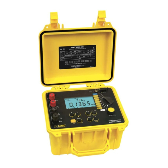
- Page 1 ■ 6255 MICRO-OHMMETER ENGLISH User Manual 1.800.561.8187 information@itm.com www. .com...
- Page 2 Statement of Compliance ® ® Chauvin Arnoux , Inc. d.b.a. AEMC Instruments certifies that this instrument has been calibrated using standards and instruments traceable to international standards. We guarantee that at the time of shipping your instrument has met its published specifications.
-
Page 3: Table Of Contents
9.1. Warning ..................... 46 9.2. Cleaning .................... 46 9.3. Charging/Recharging the Battery ............46 9.4. Battery and Fuse Replacement ............47 REPAIR AND CALIBRATION ................48 TECHNICAL AND SALES ASSISTANCE ............48 LIMITED WARRANTY ..................49 Micro-Ohmmeter Model 6255 1.800.561.8187 information@itm.com www. .com... -
Page 4: Introduction
1. INTRODUCTION Thank you for purchasing the AEMC Micro-Ohmmeter Model 6255. For best results from your instrument and for your safety, read the enclosed operating instructions carefully and comply with the precautions for use. These products must be only used by qualified and trained users. -
Page 5: Battery Handling
Example: distribution panel, circuit-breakers, machines or fixed industrial devices. CAT II Measurement category II corresponds to measurements taken on circuits directly connected to low-voltage installations. Example: power supply to domestic electrical appliances and portable tools. Micro-Ohmmeter Model 6255 1.800.561.8187 information@itm.com www. .com... -
Page 6: Receiving Your Shipment
Save the damaged packing container to substantiate your claim. 1.5. Ordering Information Micro-ohmmeter Model 6255 …..………......…..Cat. #2129.84 Includes extra-large tool bag, set of two 10 ft. (3m) Kelvin clips (10A - Hippo), set of two 10 ft. (3m) Kelvin probes (1A - Spring Loaded), one RS-232 DB9 F/F 6 ft. -
Page 7: Features
0.05% with a maximum resolution of 0.1μΩ over seven ranges from 5mΩ to 2.5kΩ. The Model 6255 is packaged in a sealed case. It provides a rating of IP64 with cover closed (IP53 with cover open) and locking metal measuring terminals. -
Page 8: Key Features
Direct display of the measurement with its units, range, measurement mode, and (if activated) temperature compensation. Measurement can be initiated from the front panel or remotely through the 9-pin communication port Rugged, sealed case Micro-Ohmmeter Model 6255 1.800.561.8187 information@itm.com www. .com... -
Page 9: Control Features
Figure 2-1 Kelvin input terminals AC line recharging receptacle Large multi-line backlit liquid crystal display RTD temperature input Communication / remote operation port Range selection switch Test, Start/Stop button Eight program / function buttons Micro-Ohmmeter Model 6255 1.800.561.8187 information@itm.com www. .com... -
Page 10: Button Functions
UP positions. Data is viewed using the ▲ and ► buttons. The R ( ), , and ALARM buttons can be used. Turns the display backlight ON or OFF. Activates or deactivates the buzzer and adjusts the sound level. Micro-Ohmmeter Model 6255 1.800.561.8187 information@itm.com www. .com... -
Page 11: Display Symbols
Temperature displayed in either degrees Centigrade or Fahrenheit PRINT Printing current test result or tests stored in memory Displayed measurement about to be stored in memory REMOTE Instrument under computer control Memory recall Micro-Ohmmeter Model 6255 1.800.561.8187 information@itm.com www. .com... - Page 12 2500 milliohm, 1 Amp test range selected 250mΩ 10A 250 milliohm, 10 Amp test range selected 25mΩ 10A 25 milliohm, 10 Amp test range selected 5mΩ 10A 5 milliohm, 10 Amp test range selected Micro-Ohmmeter Model 6255 1.800.561.8187 information@itm.com www. .com...
-
Page 13: Specifications
Rechargeable 6V, 8.5 Ah NiMH battery pack, built-in 90 to 256V (45 to 420Hz) charger Battery Life: 5000 10A tests (typical) Battery Charging: 120/240V ± 20% (45 to 400Hz) line voltage Auto-Power Off: when battery voltage <5.0V Micro-Ohmmeter Model 6255 1.800.561.8187 information@itm.com www. .com... -
Page 14: Mechanical
Conducted and radiated emission: EN 55022, class B EN 61000-3-2 EN 61000-3-3 Immunity: EN 61000-4-2 electrostatic discharges EN 61000-4-3 radiated fields EN 61000-4-5 shock EN 61000-4-6 conducted disturbances EN 61000-4-11 voltage drops EN 61000-4-4 bursts Micro-Ohmmeter Model 6255 1.800.561.8187 information@itm.com www. .com... -
Page 15: Operation
This will be needed for temperature compensation. Activate temperature compensation by pressing the R ( ) utton. The reference temperature will appear followed by the ambient temperature on the top line of the display. Micro-Ohmmeter Model 6255 1.800.561.8187 information@itm.com www. .com... - Page 16 All information from the measurement is available for review including metal type, ambient and reference temperatures, resistance at ambient and reference temperatures, test range and test current. Typical Operational Display Figure 4-1 Micro-Ohmmeter Model 6255 1.800.561.8187 information@itm.com www. .com...
-
Page 17: Instrument Configuration (Set-Up Mode)
The right arrow ► button selects the function displayed in the top level menu and moves the cursor one place to the right or validates the programming in the sub-menus. See Cables and Printer Used with the Interface Port (§5.3) for proper connections. Micro-Ohmmeter Model 6255 1.800.561.8187 information@itm.com www. .com... - Page 18 VT100: Activates an RS-232 link between a display terminal and the Model 6255. When activated, the icon will appear on the display. Print: Activates the RS-232 link between a printer and the Model 6255 for direct printing of test results. When activated, the icon will appear on the display.
- Page 19 Press the ► button to display the firmware version. Press the ► button again to return to the top level of the Software Version set-up menu. To proceed to the next programming variable, press the ▲ button. Micro-Ohmmeter Model 6255 1.800.561.8187 information@itm.com www.
- Page 20 The program limits for the reference temperature are 32.0 to 130.0°F and -10.0 to 130.0°C. Attempting to set values outside these limits will cause error message “Err23” (Entry Out of Range) to appear in the display. Micro-Ohmmeter Model 6255 1.800.561.8187 information@itm.com www.
- Page 21 The program limits for the reference temperature are 32.0 to 130.0°F and -10.0 to 130.0°C. Attempting to set values outside these limits will cause error message “Err23” (Entry Out of Range) to appear in the display. Micro-Ohmmeter Model 6255 1.800.561.8187 information@itm.com www.
- Page 22 Centigrade (dEgC). Press the ► button to validate the selection and return to the top level of the Temperature units set-up menu. To proceed to the next programming variable, press the ▲ button. Micro-Ohmmeter Model 6255 1.800.561.8187 information@itm.com www. .com...
- Page 23 12. When Alarm 2 is set press the ► button to return to the top level of the alarm programming menu. “ALAr” will again appear on the top line and the bottom line will be blank. 13. To proceed to the next programming variable, press the ▲ button. Micro-Ohmmeter Model 6255 1.800.561.8187 information@itm.com www.
- Page 24 As you press the ▲ button, the selected object will increment accordingly. Delete the selected object by first pressing the ► button and toggling between Yes “dEL. Y” or No “dEL. n” Micro-Ohmmeter Model 6255 1.800.561.8187 information@itm.com www.
- Page 25 Only objects with data stored in them can be accessed. To return to the beginning of the SET-UP menu, press the ▲ button when “nEn” is on the top line of the display. Micro-Ohmmeter Model 6255 1.800.561.8187 information@itm.com www.
-
Page 26: Operating Procedure
The range selection may be changed while the instrument is on. A diagram of the measurement system is shown in Figure 4-2. The Model 6255 generates a current (I) from the internal voltage source (V). A voltmeter... - Page 27 On very large samples such as utility transformers, 10 to 15 minutes charging time may be necessary. Micro-Ohmmeter Model 6255 1.800.561.8187 information@itm.com www.
-
Page 28: Selecting The Test Range
4.3.5. Stand-by (ST BY) State This is the position that the Model 6255 returns to at the end of a measurement cycle after: the operator presses the START/STOP button during a test any changes to the position of the rotary switch ... -
Page 29: Measurement Modes
) is measured and the measurement R = (V ) / I is displayed. All subsequent measurements comprise only a V measurement as V remains in memory. The timing sequence for measurement is shown in Figure 4-5. Micro-Ohmmeter Model 6255 1.800.561.8187 information@itm.com www. .com... - Page 30 After ending the measurement, with the current turned off, the Model 6255 will discharge the device under test as long as the test leads are connected to the device. Figure 4-5 C = connection check 0 = residual voltage measurement (stored) 1,2,3…n = successive voltage measurements across the resistor terminals...
- Page 31 ) / I is displayed or error message “Err 07” is displayed, if an over range condition occurs. The Model 6255 then returns to the Stand-by state at the end of the measurement. The instrument is ready to perform another measurement.
- Page 32 When the desired location has been selected, press the MEM button a second time to complete the data storage process. The test is stopped by pressing the START/STOP button. Micro-Ohmmeter Model 6255 1.800.561.8187 information@itm.com www.
-
Page 33: Ambient Temperature Compensation
The alpha values for copper and aluminum are pre-programmed into the Model 6255. Others may be programmed by selecting Other Metals and then programming in the alpha constant from the table or other sources. Micro-Ohmmeter Model 6255 1.800.561.8187... - Page 34 0.130 Table 2 100Ω platinum RTD can be connected to the front panel of the Model 6255 to perform compensated measurements. The temperature sensor and extension cable assembly, listed in the Accessories section, are recommended. The three pin temperature compensation port is located to the left of the interface port and...
- Page 35 Figure 4-9 Place the temperature sensor in contact with the specimen or in close proximity to it. Allow 2 minutes for the sensor to normalize to the specimen temperature before starting a temperature compensated measurement. Micro-Ohmmeter Model 6255 1.800.561.8187 information@itm.com www.
-
Page 36: Activating Alarms
Measured temperature is out of range (14 to 131°F [-10° to 55°C]) If the temperature is out of range or if the sensor leads are disconnected, the Model 6255 displays “Err 10”. Temperature compensation can be toggled ON or OFF after the measurement is completed, in resistive and inductive modes or at any time in AUTO mode. -
Page 37: Memory/Printing
If an occupied location is selected, the OCC message blinks to warn that this memory location is already taken. Storage action in this location requires pressing the MEM button again. The previous measurement in this location will be replaced by the new measurement. Micro-Ohmmeter Model 6255 1.800.561.8187 information@itm.com www. -
Page 38: Displaying And Printing Stored Measurements
Press the PRINT button to print the measurement results stored at the current memory location. An optional serial printer is required for this feature. Only memory locations with stored measurements are accessible. Micro-Ohmmeter Model 6255 1.800.561.8187 information@itm.com www. .com... - Page 39 Use the arrow buttons to select the object and test to be printed. A typical printed report using an optional printer is shown below. Figure 5-1 Blank report forms can be downloaded from the AEMC web site. Micro-Ohmmeter Model 6255 1.800.561.8187 information@itm.com www.
-
Page 40: Cables And Printers Used With The Interface Port
The main connection pins used are shown in Figures 5-3 and 5-4 respectively. Connection to a PC or Terminal: Male Connector Female Connector Printer end Printer end 6255 end Figure 5-3 Micro-Ohmmeter Model 6255 1.800.561.8187 information@itm.com www. .com... - Page 41 Direct Printer Connection: Male Connector Female Connector Printer end Printer end Figure 5-4 Micro-Ohmmeter Model 6255 1.800.561.8187 information@itm.com www. .com...
-
Page 42: Dataview
Open the DataView folder on your desktop. This displays a list of icons for the Control Panel(s) installed with DataView. Open the DataView Micro-Ohmmeter Control Panel by clicking the icon. For more information, consult the DataView Micro-Ohmmeter Control Panel Help. Micro-Ohmmeter Model 6255 1.800.561.8187 information@itm.com www. .com... -
Page 43: Troubleshooting
7. TROUBLESHOOTING The Model 6255 incorporates internal diagnostics and will inform the operator of any condition needing attention through the use of error messages. The available messages are described here. 7.1. Fault Indicators Err 1 Low battery level Err 2... -
Page 44: Application Examples
8. APPLICATION EXAMPLES The proper procedures for using the Model 6255 in some specific applications are described in this section. 8.1. Measuring Winding Resistance of Motors and Transformers WARNINGS: Prior to and after testing a transformer winding, the energy stored in the magnetic field must be dissipated by shorting the transformer terminals. -
Page 45: Measuring Resistance On Electric Motors
Each individual cell resistance should not exceed the average by more than 10%. See the manufacturer’s specifications for typical resistance values. Figure 8-3 Micro-Ohmmeter Model 6255 1.800.561.8187 information@itm.com www. -
Page 46: Maintenance
110V line cord, which provides the charging voltage for the rechargeable battery. CHARGING THE BATTERY The Model 6255 should be fully charged before using it for the first time. This may take up to 6 hours for a completely discharged battery. If the battery symbol is flashing, the battery needs to be recharged. -
Page 47: Battery And Fuse Replacement
Connect the Model 6255 to 120V using the power cord provided (charging starts automatically). Testing cannot be conducted while charging the batteries. Button presses are ignored when charging is in process. CHARGING INDICATORS bAt on the small display and CHrg on the main display, signifies fast charging in progress. -
Page 48: Repair And Calibration
TECHNICAL AND SALES ASSISTANCE If you are experiencing any technical problems, or require any assistance with the proper operation or application of your instrument, please call, fax, or e-mail our technical support team: Micro-Ohmmeter Model 6255 1.800.561.8187 information@itm.com www. .com... -
Page 49: Limited Warranty
Instruments, not by the distributor from whom it was purchased. This warranty is void if the unit has been tampered with, abused, or if the defect is ® related to service not performed by AEMC Instruments. Please print the online Warranty Coverage Information for your records. - Page 50 NOTES Micro-Ohmmeter Model 6255 1.800.561.8187 information@itm.com www. .com...
- Page 51 NOTES Micro-Ohmmeter Model 6255 1.800.561.8187 information@itm.com www. .com...
- Page 52 01/18 99-MAN 100458 v1 Chauvin Arnoux ® , Inc. d.b.a. AEMC ® Instruments 1.800.561.8187 information@itm.com www. .com...
Need help?
Do you have a question about the 6255 and is the answer not in the manual?
Questions and answers