
Related Manuals for AEMC 6240


Summary of Contents for AEMC 6240
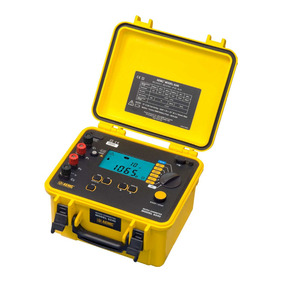
- Page 1 User Manual ENGLISH Micro-Ohmmeter Model 6240 NOTE: For instruments with a serial number lower than 116339SEDV, terminals C1 and P1 are red, and C2 and P2 are black. MICRO-OHMMETERS WITH AEMC INSTRUMENTS ®...
- Page 2 Copyright Chauvin Arnoux , Inc. d.b.a. AEMC Instruments. All rights reserved. © ® ® No part of this documentation may be reproduced in any form or by any means (including electronic storage and retrieval or translation into any other language) without prior agreement and written consent from Chauvin Arnoux , Inc., as governed by United States and International copyright laws.
- Page 3 Statement of Compliance Chauvin Arnoux , Inc. d.b.a. AEMC Instruments ® ® certifies that this instrument has been calibrated using standards and instruments traceable to international standards. We guarantee that at the time of shipping your instrument has met the instrument’s published specifications.
-
Page 4: Table Of Contents
TABLE OF CONTENTS 1. INTRODUCTION...............6 1.1 INTERNATIONAL ELECTRICAL SYMBOLS ......... 6 1.2 DEFINITION OF MEASUREMENT CATEGORIES (CAT) ... 6 1.3 PRECAUTIONS FOR USE ............6 1.4 BATTERY HANDLING ..............7 1.5 RECEIVING YOUR SHIPMENT ............. 8 1.6 ORDERING INFORMATION ............8 1.6.1 Accessories .................. - Page 5 4.9 ERASING MEASUREMENTS FROM MEMORY ......23 4.9.1 Erasing Selected Measurements ..........23 4.9.2 Erasing Selected Measurements ..........23 5. DATAVIEW SOFTWARE ............24 ® 5.1 INSTALLING DATAVIEW ............24 ® 5.2 MICRO-OHMMETER CONTROL PANEL ........25 6. TROUBLESHOOTING ............26 6.1 ERROR MESSAGES ..............26 6.1.1 Voltage Present ................
-
Page 6: Introduction
■ This instrument is protected from accidental voltages of not more than 50 V with respect to earth in measurement CAT III. ■ Do not attempt to perform any tests with this instrument until you have read the user manual. Micro-Ohmmeter Model 6240 - User Manual... -
Page 7: Battery Handling
■ Only charge your instrument at temperatures between (32 and 104) °F (0 and 40) °C. ■ Comply with the conditions of use defined in this user manual. ■ Comply with the storage conditions specified in this user manual. Micro-Ohmmeter Model 6240 - User Manual... -
Page 8: Receiving Your Shipment
WARNING: Charge the instrument fully before use. 1.6 ORDERING INFORMATION Micro-Ohmmeter Model 6240 ............Cat. #2129.80 Includes extra-large tool bag, set of two 10 ft Kelvin clips (10 A - Hippo), set of two 10 ft Kelvin Probes (1 A - Spring Loaded), optical USB cable, US 115 V power cord, two spare fuses (12.5 A), NiMH rechargeable battery... -
Page 9: Replacement Parts
Kelvin Probes 10 ft (3 m) 1 A Spring Loaded........Cat. #2118.73 Battery Pack - Replacement NiMH 6 V 9000 mAH for Models 6240, 6250 and 6255 ............Cat. #2129.91 Extra-large Classic Tool Bag .............Cat. #2133.73 Fuse, set of 5, 12.5 A/500 V (Fast Blow), 6.3 x 32 mm .....Cat. #2129.92 Cable - Optical USB Cable ..............Cat. -
Page 10: Features
0.25 %. A built-in circuit filters out AC signals. The Micro-ohmmeter Model 6240 is packaged in a sealed field case well suited for shop and field use. Power is supplied by a long-life NiMH battery pack with a built-in charger (110/220 V). -
Page 11: Key Features
AC line (110 to 230 V, 50/60 Hz) using a standard line cord ■ 4-Wire measurement with automatic compensation of undesirable voltages and lead resistance ■ Large multi-function backlit display ■ Direct display of the measurement with units, range and test current ■ Rugged, sealed case Micro-Ohmmeter Model 6240 - User Manual... -
Page 12: Control Features
Output fuse - 12.5 A, 500 V, 6 x 32 mm Large multi-line backlit liquid crystal display (see § 2.6) Optical interface connector for connection to a PC Range selection switch Start/Stop button Program/Function buttons (see § 2.5) Micro-Ohmmeter Model 6240 - User Manual... -
Page 13: Button Functions
Activates automatic recordings. Used in the SET-UP and memory mode, selects a function or ▲ increments a flashing parameter. Used in the SET-UP and memory mode, accesses the function ► to be modified. Erases the memory Micro-Ohmmeter Model 6240 - User Manual... -
Page 14: Display Symbols
First position locator for data stored in memory TEST Second position locator for data stored in memory ºC / ºF Not used Memory utilization indicator R (+I) + R (-I) Displays average Not used > Indicates an overrange Micro-Ohmmeter Model 6240 - User Manual... -
Page 15: Specifications
*Example: If the measured resistance is 1 mΩ and the measurement current is 10 A, an alternating voltage of 1 mV in series with the resistance to be measured will induce an error of not more than 2 % Micro-Ohmmeter Model 6240 - User Manual... -
Page 16: Mechanical
The instrument satisfies the CEM and DBT directives required for the CE marking and product standard EN 61326-1 Emissions in residential environment Immunity in industrial environment NOTE: Specifications are subject to change without notice Micro-Ohmmeter Model 6240 - User Manual... -
Page 17: Operation
® To configure the Model 6240 directly from the display, turn the rotary switch to the SET-UP position. The following screen will appear: ■ The display order of the parameters that can be modified is: –... -
Page 18: Resistance Measurements
6. To display the voltage on the terminals of the resistance instead of the measurement current, press the DISPLAY key. Current results are displayed Voltage results are displayed before pressing DISPLAY button after pressing DISPLAY button Micro-Ohmmeter Model 6240 - User Manual... -
Page 19: Measurement Readings
4.3.2 Connections and Readings The Model 6240 generates a current (I) from the internal voltage source (V). A voltmeter measures the voltage drop... -
Page 20: Repetitive Measurements
R(+I) + R(-I) 2. To display the values R(+I) and R(-I), press the DISPLAY button. HOLD HOLD R(+I) R(+I) R(-I) R(-I) µ Ω Press the DISPLAY button to cycle through the values Micro-Ohmmeter Model 6240 - User Manual... -
Page 21: Automatic Recording
2. Press the MEM button. 3. When the button is pressed, the MEM symbol flashes and the small display indicates the first free OBJ : TEST number (e.g. 01 : 01). The main display indicates Micro-Ohmmeter Model 6240 - User Manual... - Page 22 OBJ. TEST Indicates address is already occupied Over- Exits without writes the Recording Memory Display shown if memory is full: Display shown if memory is empty: +I +I +I +I OBJ. OBJ. TEST TEST Micro-Ohmmeter Model 6240 - User Manual...
-
Page 23: Recalling Results From Memory
1. Turn the rotary switch to Set-up. The default display appears: 2. Press for >2s. will blink. 3. Press again. will display. 4. Press again for >2s. All measurements are erased and the screen returns to the default display. Micro-Ohmmeter Model 6240 - User Manual... -
Page 24: Dataview ® Software
Click Exit to close. The DataView folder appears on your computer desktop. 7. Open the DataView folder on your desktop. This displays a list of icons for the Control Panel(s) installed with DataView. Micro-Ohmmeter Model 6240 - User Manual... -
Page 25: Micro-Ohmmeter Control Panel
Control Panel icon. For users who interact with micro-ohmmeter instruments, we recommend primarily using the Control Panel. However, there are situations where using the core DataView icon may be more convenient, such as when viewing multiple archived reports from different AEMC Instruments product ®... -
Page 26: Troubleshooting
The > symbol indicates an overrange condition. Switch to a higher measurement range and restart the measurement until the > symbol no longer appears. +I +I This symbol > indicates an overrange µ Ω Micro-Ohmmeter Model 6240 - User Manual... -
Page 27: Noisy Measurement
6.1.4 Overheating Internal overheating can occur if a measurement in the 10 A range last for several minutes. No measurement is possible until the temperature symbol and indication are no longer visible. +I +I ° Micro-Ohmmeter Model 6240 - User Manual... -
Page 28: Maintenance
110 V line cord, which provides the charging voltage for the rechargeable battery. CHARGING THE BATTERY ■ The Model 6240 should be charged to a full charge before using it for the first time. ■ Charging to full capacity may take up to 6 h for a completely discharged battery. - Page 29 ■ In the OFF mode, indication is as described in the charging indicator section below. Connect the Model 6240 to 110 V using the power cord provided (charging starts automatically if the instrument is in the OFF mode).
-
Page 30: Battery And Fuse Replacement
Fax: (603) 742-2346 E-mail: repair@aemc.com (Or contact your authorized distributor.) Contact us for the costs for repair, standard calibration, and calibration traceable to N.I.S.T. NOTE: You must obtain a CSA# before returning any instrument. Micro-Ohmmeter Model 6240 - User Manual... -
Page 31: Technical Assistance
Instruments, not by the distributor from whom it was purchased. This ® warranty is void if the unit has been tampered with, abused, or if the defect is related to service not performed by AEMC Instruments. ® Full warranty coverage and product registration is available on our www.aemc.com/warranty.html. - Page 32 99-MAN 100324 v30 AEMC Instruments ® 15 Faraday Drive • Dover, NH 03820 USA Phone: +1 (603) 749-6434 • +1 (800) 343-1391 • Fax: +1 (603) 742-2346 www.aemc.com © 2016 Chauvin Arnoux , Inc. d.b.a. AEMC Instruments. All Rights Reserved. ® ®...
Need help?
Do you have a question about the 6240 and is the answer not in the manual?
Questions and answers