Table of Contents
Advertisement
Quick Links
Download this manual
See also:
User Manual
Advertisement
Table of Contents

Related Manuals for AEMC 6240


Summary of Contents for AEMC 6240
- Page 1 6240 MICRO-OHMMETER NOTE: For instruments with serial numbers lower than 116339SEDV, terminals C1 and P1 are red, and C2 and P2 are black E N G L I S H User Manual...
- Page 3 The recommended calibration interval for this instrument is 12 months and begins on the date of receipt by the customer. For recalibration, please use our calibration services. Refer to our repair and calibration section at www.aemc.com. Serial #: ________________________________ Catalog #: 2129.80 Model #:...
-
Page 4: Table Of Contents
Table of Contents 1. INTRODUCTION ................. 4 1.1 International Electrical Symbols ..........5 1.2 Definition of Measurement Categories ........5 1.3 Receiving Your Shipment ............5 1.4 Ordering Information ..............6 1.4.1 Accessories and Replacement Parts ......6 2. PRODUCT FEATURES ................. 7 2.1 Description ................7 2.2 Applications ................8 2.3 Key Features ................8 2.4 Control Features ...............9 2.5 Button Functions ..............10 2.6 Display Symbols .............. - Page 5 6.1 Error Messages ..............27 6.1.1 Voltage Present ............27 6.1.2 Overrange ..............28 6.1.3 Noisy Measurement ............28 6.1.4 Overheating ..............28 7. MAINTENANCE ................29 7.1 Warning ..................29 7.2 Cleaning ..................29 7.3 Charging/Recharging the Battery ...........30 7.4 Battery and Fuse Replacement ..........31 Repair and Calibration ..............32 Technical and Sales Assistance ............32 Limited Warranty ................33 Warranty Repairs ................33 Micro-Ohmmeter Model 6240...
-
Page 6: Introduction
(50V CAT III). Use only accessories that comply with safety standards (IEC 61010-2- 031). • The test leads and measuring wires must be in good condition and should be replaced if there is any evidence of deterioration (insulation split, burnt, etc.). • Troubleshooting and metrological verification procedures must only be performed by qualified, approved personnel, or the factory. Micro-Ohmmeter Model 6240... -
Page 7: International Electrical Symbols
CAT II: For measurements performed on circuits directly connected to the electrical distribution system. Examples are measurements on household appliances or portable tools. Receiving Your Shipment Upon receiving your shipment, make sure that the contents are consistent with the packing list. Notify your distributor of any missing items. If the equip- ment appears to be damaged, file a claim immediately with the carrier and notify your distributor at once, giving a detailed description of any damage. Save the damaged packing container to substantiate your claim. NOTE: Charge the instrument fully before use. Micro-Ohmmeter Model 6240... -
Page 8: Ordering Information
Ordering Information Micro-ohmmeter Model 6240 ..........Cat. #2129.80 Includes extra large tool bag, set of two 10ft Kelvin clips (10A - Hippo), set of two 10ft Kelvin probes (1A - Spring Loaded), optical USB cable, US 115V power cord, two spare fuses (12.5A), NiMH rechargeable battery pack, and USB stick supplied with product user manual... -
Page 9: Product Features
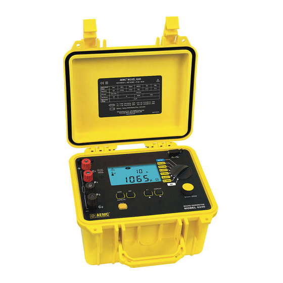
CHAPTER 2 PRODUCT FEATURES Description The Micro-ohmmeter Model 6240 is used to perform low resistance measurements from 5μΩ to 400Ω. There are six ranges with test currents from 10mA to 10A. The front end of the micro-ohmmeter employs a four-wire Kelvin configu- ration, which eliminates test lead resistance for a measurement accuracy of 0.25%. A built-in circuit filters out AC signals. The Micro-ohmmeter Model 6240 is packaged in a sealed field case well suited for shop and field use. Power is supplied by a long-life NiMH battery pack with a built-in recharger (110/220V). The large, easy-to-read liquid crystal display is 2.25 x 4.00". It displays the value of resistance, current or voltage test, polarity and battery charge. For operator safety and instrument protection, the micro-ohmmeter is fuse protected at the inputs. One fuse, accessible from the front panel, protects against stored energy in inductive loads. Enhanced internal circuitry protects against possible inductive kickback when the current is shut off. A built-in thermal switch protects the micro-ohmmeter against overheating on the 10A range when in continuous use. -
Page 10: Applications
Measures from 5µΩ to 400Ω • Test current selection from 10mA to 10A • Manual temperature compensation (with DataView software) ® • Front panel polarity reverse function • Stores up to 99 test results • Operator safety by automatic discharge of residual charge on the equipment under test • Instantaneous, continuous or multiple test operation • Auto store of multiple test results • Internal, rechargeable batteries conduct up to 850, 10A tests • A built-in battery pack recharger recharges the batteries by connecting to the AC line (110V-230V, 50/60Hz) using a standard line cord • 4-Wire measurement with automatic compensation of undesirable voltages and lead resistance • Large multi-function backlit display • Direct display of the measurement with units, range and test current • Rugged, sealed case Micro-Ohmmeter Model 6240... -
Page 11: Control Features
Control Features MEMMRCLR °C°F ° HOLD OBJ. TEST > < µmΩ Figure 2-1 1. Kelvin input terminals 2. AC line recharging receptacle 3. Output fuse - 12.5A, 500V, 6x32mm 4. Large multi-line backlit liquid crystal display (see § 2.6) 5. Optical interface connector for connection to a computer 6. Range selection switch 7. Start/Stop button 8. Program /function buttons (see § 2.5) Micro-Ohmmeter Model 6240... -
Page 12: Button Functions
Displays the current or voltage on the terminals. AUTO>2s Activates automatic recordings. Used in the SET-UP and memory mode, selects a function or incre- ments a flashing parameter. Used in the SET-UP and memory mode, accesses the function to be modified. Erases the memory Micro-Ohmmeter Model 6240... -
Page 13: Display Symbols
Indicates that a measurement has been stopped OBJ. First position locator for data stored in memory TEST Second position locator for data stored in memory °C / °F Not used Memory utilization indicator R (+I) + R (-I) Displays average Not used > Indicates an overrange Micro-Ohmmeter Model 6240... -
Page 14: Specifications
40.0 to 0.40 to 4.0 to Range 3.999mV 39.99mV 399.9mV 3.999V 4.70V Resolution 1µV 10µV 100µV 10mV CURRENT MEASUREMENT INDICATION Measurement 5.0 to 40.0 to 0.40 to 4.0 to Range 39.99mA 399.9mA 3.999A 11.00A Resolution 10µA 100µA 10mA Micro-Ohmmeter Model 6240... -
Page 15: Mechanical
Range Number of measurements* 3500 100mA 4500 10mA 5000 In Standby or Off battery life 4 to 6 months *Established for measurements lasting 5s, every 25s. Mechanical Dimensions: 10.70 x 9.76 x 7.17" (272 x 248 x 182mm) Weight: 10 lbs (4.5kg approx) Case Protection: ABS plastic polycarbonate: watertight to IP64 (cover closed), water resistant to IP53 (cover open). Color: Safety yellow case with gray faceplate Micro-Ohmmeter Model 6240... -
Page 16: Environmental
-4 to 86°F (-20 to 30°C); 85% RH, otherwise the battery will deteriorate. For short-term storage (1 month) the temperature can reach up to 122°F (50°C). Safety Electrical safety as per EN 61010-1 (Ed. 2 of 2001), EN 61557 (Ed. 97) parts 1 and 4. Degree of pollution: 2 Protection: Measurement CAT III, 50V with respect to earth, 500V differ- ential between terminals, and 300V CAT II on the charger input Electromagnetic Compatibility: The instrument satisfies the CEM and DBT directives required for the CE marking and product standard EN 61326-1 (Ed. 97) + A1 (Ed. 98) Emissions in residential environment Immunity in industrial environment *Specifications are subject to change without notice Micro-Ohmmeter Model 6240... -
Page 17: Operation
Never disconnect the connection wires before the • icon disappears from the display. Instrument Configuration (SET-UP mode) The SET-UP mode is used to modify the instrument’s configuration. This can also be performed by using the DataView software that came with ® the instrument. To configure the Model 6240 directly from the display, turn the rotary switch to the SET-UP position. The following screen will appear: • The display order of the parameters that can be modified is: Clear all memory (see § 4.9.2) Time Date Automatic Power Off Display of the Internal Parameters (e.g. serial number, software version, date of last calibration, lighting of all segments on display) Micro-Ohmmeter Model 6240... -
Page 18: Resistance Measurements
The range selection may be changed while the instrument is on. HOLD 5. Press the START/STOP button again to stop the measurement or disconnect one of the Kelvin clips. The last measurement made is displayed along with the symbol. Micro-Ohmmeter Model 6240... -
Page 19: Measurement Readings
4.3.2 Connections and Readings The Model 6240 generates a current (I) from the internal voltage source (V). A voltmeter measures the voltage drop at the Kelvin probe contact points to the resistance to be measured (R ) and... -
Page 20: Test Lead Connection
3. Connect the clips to the second object. The measurement restarts automatically. Repeat as necessary. 4. After the last measurement, press START/STOP again. NOTE: This operation is valid only if all of the objects to be measured have substantially the same value and all of the measurements are made in the same range. Micro-Ohmmeter Model 6240... -
Page 21: Measuring Very Low Resistance
Measuring Very Low Resistance When measuring very low resistive values in the µΩ range, the presence of stray DC currents may affect the accuracy of the measurements. These currents can be present due to a variety of reasons including chemical or thermal EMF in samples made of dissimilar metals. You can eliminate the effects of this by reversing the direction of current flow (see example below) and using the average of forward and reverse readings. The presence of AC interference in the sample under test may cause the measured value on the display to fluctuate. This interference may become more noticeable in the presence of strong electric fields. The effects of this interference may be reduced by twisting the leads around each other. 1. Reverse the direction of the current by pressing the ±I button and the instrument displays the average: R(+I) + R(-I) 2. To display the values R(+I) and R(-I), press the DISPLAY button. HOLD R(+I) R(+I) R(-I) R(-I) µ Ω Press the DISPLAY button to cycle through the values Micro-Ohmmeter Model 6240... -
Page 22: Automatic Recording
Use the arrow buttons to change the values of the OBJ and TEST OBJ. TEST > 2s When finished, press the MEM button for >2s 5. Press the START/STOP button to begin measuring. At each new measurement, the test number is incremented and the measurement is recorded. 6. Press the START/STOP button again to stop automatic recording. HOLD OBJ. TEST µ Ω Micro-Ohmmeter Model 6240... -
Page 23: Storing Results Into Memory
TEST option, then use the button to change the number of the test or object. 5. When finished, press the MEM button for >2s. The measurement is stored. Use the arrow buttons to change the values of the OBJ and TEST OBJ. TEST > 2s When finished, press the MEM button for >2s 6. If the user selects a memory address that is already occupied, appears on the main screen. To overwrite the location, press the MEM button for >2s. Micro-Ohmmeter Model 6240... -
Page 24: Recalling Results From Memory
Exits without Memory Recording Display shown if memory is full: Display shown If memory is empty: OBJ. OBJ. TEST TEST Recalling Results from Memory 1. Make sure there is no measurement in progress. 2. Press the MR button. 3. Use the buttons to select the desired OBJ and TEST. 4. Press the MR button again to exit the memory function. Use the arrow buttons to change the values of the OBJ and TEST Micro-Ohmmeter Model 6240... -
Page 25: Erasing Measurements From Memory
OBJ and TEST OBJ. TEST OBJ. TEST > 2s µ Ω When finished, press the CLR button for > 2s 4.9.2 Erasing All Measurements 1. Turn the rotary switch to Set-up. The default display appears: 2. Press for >2s. will blink. 3. Press will display. again. 4. Press again for >2s. All measurements are erased and the screen returns to the default display. Micro-Ohmmeter Model 6240... -
Page 26: Dataview ® Software
® DO NOT CONNECT THE INSTRUMENT TO THE PC BEFORE INSTALLING THE SOFTWARE AND DRIVERS. When you purchase an AEMC instrument supported by DataView, the software is included as part of the product package. DataView program files are stored on a USB stick. NOTE: When installing, the user must have Administrative access rights during the installation. The users access rights can be changed... - Page 27 French, or Spanish) then click Next. (By default, the language selected in step 3 is highlighted.) 5. You are now prompted to select the software you want to install. Each AEMC product family has its own specially designed Control Panel. If you are performing a Complete install, by default all available Control Panels are selected (a check mark next to the Control Panel indicates it is selected). Control Panels take up disk space on the computer; so unless you have other types of AEMC instruments, we recommend that you select MicroOhmmeter and deselect the rest. You should also check the option DataView Core, which is a requirement if you plan to create DataView reports. After you finish selecting and deselecting Control Panels and/or Data- View Core, click Next. 6. The Setup program now informs you that it is ready to install Data- View. If you want to review any of your previous selections, click the...
-
Page 28: Micro-Ohmmeter Control Panel
DataView icon or the Control Panel icon. For users who interact with micro-ohmmeter instruments, we recommend primarily using the Control Panel. However, there are situations where using the core DataView icon may be more convenient for some users, such as when viewing multiple archived reports from different AEMC product families. For further information about using the MicroOhmmeter Control Panel, consult the Help system that comes with the product. Access this Help by clicking the option Help in the Control Panel’s menu bar at the top of the screen.. Micro-Ohmmeter Model 6240... -
Page 29: Troubleshooting
CHAPTER 6 TROUBLESHOOTING Error Messages 6.1.1 Voltage Present An error message will appear when an external voltage is present on the device being measured. (e.g. C1C2 or C1P1). Before a measurement is possible the voltage must be removed from the test object. A voltage greater than 20V applied across the C1-C2 terminal will cause the Fuse on the front panel to blow. (See §7.4 for fuse replacement) Micro-Ohmmeter Model 6240... -
Page 30: Overrange
This symbol indicates noisy measurement µ Ω 6.1.4 Overheating Internal overheating can occur if a measurement in the 10A range last for several minutes. No measurement is possible until the temperature symbol and indication are no longer visible. ° Micro-Ohmmeter Model 6240... -
Page 31: Maintenance
CHAPTER 7 MAINTENANCE Use only factory specified replacement parts. AEMC will not be held ® responsible for any accident, incident, or malfunction following a repair done other than by its service center or by an approved repair center. Warning • To avoid electrical shock, do not attempt to perform any servicing unless you are qualified to do so. • Do not perform any service while the micro-ohmmeter is on any circuit. • To avoid electrical shock and/or damage to the instrument, do not get water or other foreign agents into the electronic module. • Make sure the internal battery is fully charged prior to testing. If the instrument has been left unused for several months, recharge the battery. -
Page 32: Charging/Recharging The Battery
OFF again. CHARGING INDICATORS OFF Mode: • bAtt on the small display and ### on the main display, signifies fast charging in progress. Where ### is the percent of battery charge (only in the OFF position). • bAtt on the small display and FULL on the main display, signifies that charging is complete. At this point a low charge current is applied to maintain the battery charge. Micro-Ohmmeter Model 6240... -
Page 33: Battery And Fuse Replacement
• The battery is accessible using a Phillips Head screwdriver to remove the four screws on the bottom side of the case and pulling the chassis out from the top. FUSE • The fuse is located on the front panel between the C1 and P1 input terminals. • Fuse F1, is a 6.3x32 mm, fast acting, 12.5A/500V, low internal resistance, protecting the current source from outside voltages on energized specimens. Micro-Ohmmeter Model 6240... -
Page 34: Repair And Calibration
NOTE: You must obtain a CSA# before returning any instrument. Technical and Sales Assistance If you are experiencing any technical problems, or require any assistance with the proper operation or application of your instrument, please call, mail, fax or e-mail our technical support team: Chauvin Arnoux , Inc. d.b.a. AEMC Instruments ® ® 200 Foxborough Boulevard Foxborough, MA 02035 USA Phone: (800) 343-1391 (508) 698-2115 Fax: (508) 698-2118 E-mail: techsupport@aemc.com www.aemc.com NOTE: Do not ship Instruments to our Foxborough, MA address. Micro-Ohmmeter Model 6240... -
Page 35: Limited Warranty
CSA Form. Please write the CSA# on the outside of the shipping container. Return the instrument, postage or shipment pre-paid to: Ship To: Chauvin Arnoux , Inc. d.b.a. AEMC Instruments ® ® 15 Faraday Drive • Dover, NH 03820 USA Phone: (800) 945-2362 (Ext. 360) (603) 749-6434 (Ext. 360) Fax: (603) 742-2346 or (603) 749-6309 E-mail: repair@aemc.com Caution: To protect yourself against in-transit loss, we recommend you insure your returned material. NOTE: You must obtain a CSA# before returning any instrument. Micro-Ohmmeter Model 6240... - Page 36 10/19 99-MAN 100324 v24 Chauvin Arnoux , Inc. d.b.a. AEMC Instruments ® ® 15 Faraday Drive • Dover, NH 03820 USA • Phone: (603) 749-6434 • Fax: (603) 742-2346 www.aemc.com...
Need help?
Do you have a question about the 6240 and is the answer not in the manual?
Questions and answers