Table of Contents
Advertisement
Quick Links
Advertisement
Table of Contents

Related Manuals for Supermicro SuperServer E100-9S


Summary of Contents for Supermicro SuperServer E100-9S
- Page 1 ® UpER ERvER E100-9S/-9S-E/-9S-L USER’S MANUAL Revision 1.0...
- Page 2 State of California, USA. The State of California, County of Santa Clara shall be the exclusive venue for the resolution of any such disputes. Supermicro's total liability for all claims will not exceed the price paid for the hardware product.
- Page 3 If you have any questions, please contact our support team at: support@supermicro.com This manual may be periodically updated without notice. Please check the Supermicro website for possible updates to the manual revision level. Warnings Special attention should be given to the following symbols used in this manual.
-
Page 4: Table Of Contents
SuperServer E100-9S/-9S-E/-9S-L User's Manual Contents Chapter 1 Introduction 1.1 Overview ..........................7 1.2 System Features ........................8 1.3 I/O Features .........................9 Front I/O Features .......................9 Rear I/O Features ......................10 1.4 Motherboard Layout ......................11 Quick Reference Table ......................12 System Block Diagram ......................13 1.5 System Installation ......................14 Unpacking the System ......................14... - Page 5 Preface Chapter 4 Software Installation 4.1 Driver Installation ........................30 4.2 SuperDoctor 5 ........................31 ® Chapter 5 BIOS 5.1 Introduction .........................32 Starting the Setup Utility ....................32 5.2 Main Page ..........................33 5.3 Advanced Page ........................34 5.4 Security ..........................56 5.5 Boot ............................61 5.6 Save & Exit .........................64 Appendix A BIOS Error Codes Appendix B Standardized Warning Statements for DC Systems Appendix C System Specifications...
- Page 6 SuperServer E100-9S/-9S-E/-9S-L User's Manual Contacting Supermicro Headquarters Address: Super Micro Computer, Inc. 980 Rock Ave. San Jose, CA 95131 U.S.A. Tel: +1 (408) 503-8000 Fax: +1 (408) 503-8008 Email: marketing@supermicro.com (General Information) support@supermicro.com (Technical Support) Website: www.supermicro.com Europe Address: Super Micro Computer B.V.
-
Page 7: Chapter 1 Introduction
Product drivers and utilities: ftp://ftp.supermicro.com • Product safety info: http://www.supermicro.com/about/policies/safety_information.cfm • If you have any questions, please contact our support team at: support@supermicro.com This manual may be periodically updated without notice. Check the Supermicro website for possible updates to the manual revision level. -
Page 8: System Features
SuperServer E100-9S/-9S-E/-9S-L User's Manual 1.2 System Features The following table provides an overview of the main features of the E100-9S/-9S-E/-9S-L. Refer to Appendix C for additional specifications. System Features Motherboard E100-9S: X11SSN-H-WOHS E100-9S-E: X11SSN-E-WOHS E100-9S-L: X11SSN-L-WOHS Chassis SCE-101-01 E100-9S: 7th Generation Intel Core i7-7600U Processor (System on Chip) Socket FCBGA 1356 ®... -
Page 9: I/O Features
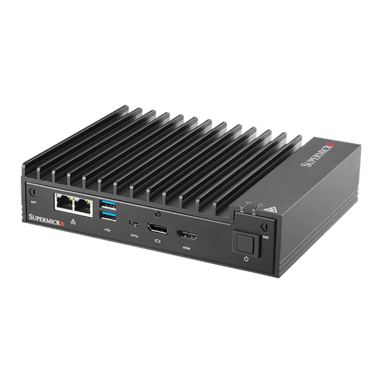
Chapter 1: Introduction 1.3 I/O Features Front I/O Features See the illustration below for the features included on the front of the chassis. Front I/O Features Item Features Description Antenna Port Two antenna ports LAN Ports Two 1Gbe LAN ports USB Ports Two USB 3.0 ports USB 3.1c Port... -
Page 10: Rear I/O Features
SuperServer E100-9S/-9S-E/-9S-L User's Manual Rear I/O Features The illustration below shows the features included on the rear of the chassis. Rear Chassis Features Item Features Description Power Input Port Port used for the 40W DC power input DIO Port A rear mounted digital I/O port USB Ports Four rear USB 2.0 ports... -
Page 11: Motherboard Layout
Chapter 1: Introduction 1.4 Motherboard Layout Below is a layout of the X11SSN-H-WOHS/-E-WOHS/-L-WOHS with jumper, connector, and LED locations shown. See the table on the following page for descriptions. For detailed descriptions, pinout information, and jumper settings, refer to Chapter 3. SRW1 FAN1 USB4/5 (3.0) -
Page 12: Quick Reference Table
SuperServer E100-9S/-9S-E/-9S-L User's Manual Quick Reference Table Jumper Description Jumper Setting Pin 1-3* (3.3V) JLCDPWR1 LVDS Panel VCC power source selection Pin 3-5 (5V) Pin 3-4 (12V) Pin 1-2* (FORCE POWER ON) JPF1 FORCE POWER ON Pin 2-3 (POWER BUTTON ON) -
Page 13: System Block Diagram
Chapter 1: Introduction System Block Diagram MAX. 16G SO-DIMM SUPPORTED per DIMM Non-ECC-SODIMM DUAL CHANNEL DDR4 2133 MHz PS175 DDI1 HDMI connector DP to HDMI2.0 DDI2 Intel DP connector PTN3460 LVDS Connector DP to LVDSBridge FLASH SPI 256Mb REALTEK High Definition Audio FRONT AUDIO Header ALC888S-VD2-GR... -
Page 14: System Installation
SuperServer E100-9S/-9S-E/-9S-L User's Manual 1.5 System Installation This section provides advice and instructions for mounting your system. The system is shipped with the onboard processor and the motherboard installed in the chassis. Unpacking the System Inspect the box in which the system was shipped and note if it was damaged. If the system itself shows damage, file a damage claim with the carrier. -
Page 15: Chapter 2 Maintenance And Component Installation
Chapter 2: Maintenance and Component Installation Chapter 2 Maintenance and Component Installation This chapter provides instructions on installing and replacing main system components. To prevent compatibility issues, only use components that match the specifications and/or part numbers given. Installation or replacement of most components require that power first be removed from the system. -
Page 16: Accessing The System
SuperServer E100-9S/-9S-E/-9S-L User's Manual 2.2 Accessing the System The E100-9S/-9S-E/-9S-L features a removable bottom cover to access to the inside of the chassis. Figure 2-1. Removing the Chassis Cover Removing the Bottom Cover 1. Power down the system as described in section 2.1. -
Page 17: Motherboard Components
Memory Support The X11SSN-H-WOHS/-E-WOHS/-L-WOHS series motherboard supports up to 32GB of DDR4 Non-ECC SODIMM memory with speeds up to 2133 MHz in two memory slots. Note: Check the Supermicro website for recommended memory modules. ® Installing Memory Caution: Exercise extreme care when installing or removing DIMM modules to prevent damage. -
Page 18: Solid State Storage
SuperServer E100-9S/-9S-E/-9S-L User's Manual 1. The side clips will automatically secure the SODIMM module, locking it into place. Locking clip SODIMM Removal 1. Push the side clips at the end of slot to release the SO-DIMM module. 2. Pull the SO-DIMM module up to remove it from the slot. -
Page 19: Installing Mounting Brackets
Chapter 2: Maintenance and Component Installation Installing Mounting Brackets The chassis includes mounting brackets that allow it to be mounted in any convenient space. 1. Install the brackets to the chassis with two screws in each bracket. 2. Secure the brackets to the surface where you want the server to be mounted. Figure 2-3. -
Page 20: Chapter 3 Motherboard Connections
SuperServer E100-9S/-9S-E/-9S-L User's Manual Chapter 3 Motherboard Connections This section describes the connections on the motherboard and provides pinout definitions. Depending on how the system is configured, not all connections are required. The LEDs on the motherboard are also described here. A motherboard layout indicating component locations can be found in Chapter 1. -
Page 21: Led Indicators
Chapter 3: Motherboard Connections HDMI Port The HDMI (High-Definition Multimedia Interface) port is used to display both high definition video and digital sound through an HDMI-capable display, using the same cable. Universal Serial Bus (USB) Ports There are two USB 3.0 ports (USB4/5) and one USB 3.0 Type C port (USB6) on the I/O back panel. -
Page 22: Headers And Connectors
SuperServer E100-9S/-9S-E/-9S-L User's Manual 3.3 Headers and Connectors SATA Power Connector The 4-pin SATA power connector JPH1 provides power to onboard HDD devices. Refer to the table below for pin definitions. 4-pin HDD Power Pin Definitions Pin# Definition Ground 12V Vertical Type Power Connector JPW2 is the 12V DC power source for the X11SSN-H-WOHS/-E-WOHS/-L-WOHS motherboard. - Page 23 Chapter 3: Motherboard Connections Front Panel Audio Header A 10-pin front panel audio header located on the motherboard allows you to use the onboard sound for audio playback. Connect an audio cable to the this header to use this feature. Refer to the table below for pin definitions.
- Page 24 SuperServer E100-9S/-9S-E/-9S-L User's Manual General Purpose I/O Header The JGP1 (General Purpose Input/Output) header is an 8-bit general purpose I/O expander on a pin header via the SMBus. Refer to the table below for pin definitions. GPIO Header Pin Definitions...
- Page 25 Chapter 3: Motherboard Connections Mini PCI-E Slot The Mini PCI-E slot, located at JMP1 on the bottom side of the motherboard, is used to install compatible Mini PCI-E and mSATA devices. The Mini PCI-E slot supports USB, one PCI-E, SATA devices, mSATA SSD, and wireless devices such as GNSS and Bluetooth modules. See the table below for pin definitions.
-
Page 26: Control Panel
JF1 contains header pins for various buttons and indicators that are normally located on a control panel at the front of the chassis. These connectors are designed specifically for use with Supermicro chassis. Refer to the figure below for the descriptions of the front control panel buttons and LED indicators. - Page 27 Chapter 3: Motherboard Connections Reset Button The Reset Button connection is located on pins 3 and 4 of JF1. Attach it to a hardware reset switch on the computer case to reset the system. Refer to the table below for pin definitions. Reset Button Pin Definition (JF1) Pin#...
-
Page 28: Jumper Settings
SuperServer E100-9S/-9S-E/-9S-L User's Manual 3.4 Jumper Settings How Jumpers Work To modify the operation of the motherboard, jumpers can be used to choose between optional settings. Jumpers create shorts between two pins to change the function of the connector. Pin 1 is identified with a square solder pad on the printed circuit board. See the diagram below for an example of jumping pins 1 and 2. - Page 29 Chapter 3: Motherboard Connections Manufacturing Mode Select Close JPME2 to bypass SPI flash security and force the system to use the Manufacturing Mode, which will allow you to flash the system firmware from a host server to modify system settings. Refer to the table below for jumper settings. Manufacturing Mode Jumper Settings Jumper Setting...
-
Page 30: Chapter 4 Software Installation
This section describes the installation of drivers and management programs for the system. 4.1 Driver Installation The Supermicro FTP site contains drivers and utilities for your system at ftp://ftp.supermicro. com. Some of these must be installed, such as the chipset driver. -
Page 31: Superdoctor ® 5
The bottom icon with a CD on it allows you to view the entire contents. 4.2 SuperDoctor ® The Supermicro SuperDoctor 5 is a hardware monitoring program that functions in a command-line or web-based interface in Windows and Linux operating systems. The program monitors system health information such as CPU temperature, system voltages, system power consumption, fan speed, and provides alerts via email or Simple Network Management Protocol (SNMP). -
Page 32: Chapter 5 Bios
SuperServer E100-9S/-9S-E/-9S-L User's Manual Chapter 5 BIOS 5.1 Introduction This chapter describes the AMI BIOS setup utility for the X11SSN-H-WOHS/-E-WOHS/-L-WOHS motherboard. It also provides the instructions on how to navigate the AMI BIOS setup utility screens. The AMI ROM BIOS is stored in a Flash EEPROM and can be easily updated. -
Page 33: Main Page
The date must be entered in Day MM/DD/YYYY format. The time is entered in HH:MM:SS format. Note: The time is in the 24-hour format. For example, 5:30 P.M. appears as 17:30:00. Supermicro X11SSN-H-WOHS/-E-WOHS/-L-WOHS BIOS Version; Build Date and Time Memory Information Total Memory: This displays the total size of memory available in the system. -
Page 34: Advanced Page
SuperServer E100-9S/-9S-E/-9S-L User's Manual 5.3 Advanced Page Use this tab page to set some boot, power, CPU, SATA, server ME, and input/output settings. Warning: Take caution when changing the Advanced settings. An incorrect value, a very high DRAM frequency or an incorrect BIOS timing setting may cause the system to malfunction. - Page 35 Chapter 5: BIOS Wait For "F1" If Error This feature forces the system to wait until the F1 key is pressed if an error occurs. The options are Disabled and Enabled. Re-try Boot If this feature is enabled, the BIOS will automatically reboot the system from a specified boot device after its initial boot failure.
- Page 36 SuperServer E100-9S/-9S-E/-9S-L User's Manual CPU Configuration The following CPU information will display: • Displays the CPU model • • Speed • L1 Data Cache • L1 Instruction Cache • L2 Cache • L3 Cache • L4 Cache • • SMX/TXT SW Guard Extentions (SGX) Use this feature to enable or disable Intel Software Guard Extensions (SGX).
- Page 37 Chapter 5: BIOS Adjacent Cache Line Prefetch Select Enabled for the CPU to prefetch both cache lines for 128 bytes as comprised. Select Disable for the CPU to prefetch both cache lines for 64 bytes. The options are Disabled and Enabled.
- Page 38 SuperServer E100-9S/-9S-E/-9S-L User's Manual Chipset Warning: Setting the wrong values in the following sections may cause the system to malfunc- tion. System Agent (SA) Configuration • SA PCIe Code Version • VT-d Memory Configuration • Memory RC Version •...
- Page 39 Chapter 5: BIOS Panel Channel Type Use this feature to select the Panel Channel Type. The options are Disabled, Odd Channel, Even Channel, and Both Channel. Dual LVDS Mode Use this feature to select a single or dual mode bus for the LVDS display. The options are Disabled, Single LVDS Bus Mode, and Dual LVDS Bus Mode, Panel Color Depth Use this feature to select the panel color depth.
- Page 40 SuperServer E100-9S/-9S-E/-9S-L User's Manual Panel Color Depth Use this feature to select the LCD panel color depth. The options are 18 Bit and 24 Bit. PCH-IO Configuration PCH-IO Configuration • USB Module Version • USB Controllers • USB Devices Legacy USB Support Select Enabled to support onboard legacy USB devices.
- Page 41 Chapter 5: BIOS Mass Storage Devices: Sony Storage Media 0100 Enable this feature for mass storage device emulation support. Select Auto to enumerate devices according to their media format. The options are Auto, Floppy, Forced FDD, Hard Disk, and CD-ROM. xDCI Support Use this feature to enable or disable the Extensible Device Controller Interface.
- Page 42 SuperServer E100-9S/-9S-E/-9S-L User's Manual PCIe/PCI/PnP Configuration Option ROM execution Video Use this feature to select which firmware type to be loaded for the add-on card in this slot. The options are Do not launch, EFI, and Legacy. Above 4G MMIO BIOS assignment Use this feature to enable or disable the above 4GB Memory Mapped IO BIOS assignment.
- Page 43 Chapter 5: BIOS NCT6106D Super IO Configuration NCT6106D Super IO Configuration Super IO Chip NCT6106D Serial Port 1 Configuration Serial Port Select Enabled to enable the onboard serial port specified by the user. The options are Disabled and Enabled. Device Settings This feature displays the base I/O port address and the Interrupt Request address of a serial port specified by the user.
- Page 44 SuperServer E100-9S/-9S-E/-9S-L User's Manual COM2 Port Mode Use this feature to select the COM port mode. The options are RS232 Mode, RS422 Mode, and RS485 Mode. Serial Port 3 Configuration Serial Port Select Enabled to enable the onboard serial port specified by the user. The options are...
- Page 45 Chapter 5: BIOS • ME Firmware SKU • ME File System Intergrity Value • ME Firmware Status 1 • ME Firmware Status 2 • NFC Support Firmware Update Configuration Me FW Image Re-Flash Use this feature to update the Management Engine firmware. The options are Disabled and Enabled.
- Page 46 SuperServer E100-9S/-9S-E/-9S-L User's Manual Bits per second Use this feature to set the transmission speed for a serial port used in Console Redirection. Make sure that the same speed is used in the host computer and the client computer. A lower transmission speed may be required for long and busy lines.
- Page 47 Chapter 5: BIOS COM2 Console Redirection Select Enabled to use the SOL port for Console Redirection. The options are Disabled and Enabled. *If the feature above is enabled, the following items are available for configuration: Console Redirection Settings Use this feature to specify how the host computer will exchange data with the client computer, which is the remote computer used by the user.
- Page 48 SuperServer E100-9S/-9S-E/-9S-L User's Manual Flow Control Use this feature to set the flow control for Console Redirection to prevent data loss caused by buffer overflow. Send a "Stop" signal to stop sending data when the receiving buffer is full. Send a "Start" signal to start sending data when the receiving buffer is empty. The options are None and Hardware RTS/CTS.
- Page 49 Chapter 5: BIOS Bits per second Use this feature to set the transmission speed for a serial port used in Console Redirection. Make sure that the same speed is used in the host computer and the client computer. A lower transmission speed may be required for long and busy lines. The options are 9600, 19200, 38400, 57600, and 115200 (bits per second).
- Page 50 SuperServer E100-9S/-9S-E/-9S-L User's Manual COM4 Console Redirection Select Enabled to use the SOL port for Console Redirection. The options are Disabled and Enabled. *If the feature above is enabled, the following items are available for configuration: Console Redirection Settings Use this feature to specify how the host computer will exchange data with the client computer, which is the remote computer used by the user.
- Page 51 Chapter 5: BIOS Flow Control Use this feature to set the flow control for Console Redirection to prevent data loss caused by buffer overflow. Send a "Stop" signal to stop sending data when the receiving buffer is full. Send a "Start" signal to start sending data when the receiving buffer is empty. The options are None and Hardware RTS/CTS.
- Page 52 SuperServer E100-9S/-9S-E/-9S-L User's Manual Serial Port for Out-of-Band Management/Windows Emergency Management Services (EMS) The submenu allows the user to configure Console Redirection settings to support Out-of- Band Serial Port management. Console Redirection Select Enabled to use a COM port selected by the user for EMS Console Redirection. The options are Enabled and Disabled.
- Page 53 Chapter 5: BIOS NCT6106D HW Monitor The following PC Health Status information will display: • System temperature • CPU temperature Fan Speed Control Mode Use this feature to select the fan speed mode. The options are Standard and Full Speed. •...
- Page 54 SuperServer E100-9S/-9S-E/-9S-L User's Manual Trusted Computing The following TPM information is displayed: TPM2.0 Device Found Vendor: IFX Firmware Version: 5.51 Security Device Support If this feature and the TPM jumper on the motherboard are both set to Enabled, onboard security devices will be enabled for TPM (Trusted Platform Module) support to enhance data integrity and network security.
- Page 55 Chapter 5: BIOS TPM2.0 UEFI Spec Version Use this feature to select the Trusted Computing Group (TCG) specification version. Version TCG_1_2 is compatible with Windows 8 and 10. Version TCG_2 is compatible with Windows 10 or later. The options are TCG_1_2 and TCG_2. Physical Presence Spec Version Use this feature to select the Physical Presence Interface version.
-
Page 56: Security
SuperServer E100-9S/-9S-E/-9S-L User's Manual 5.4 Security Use this menu to configure Security settings. Administrator Password Use this feature to set the administrator password which is required to enter the BIOS setup utility. The length of the password should be from 3 to 20 characters long. - Page 57 Chapter 5: BIOS Secure Boot Secure Boot Enable Select Enable for secure boot support to ensure system security at bootup. The options are Enabled and Disabled. Secure Boot Mode This feature allows the user to select the desired secure boot mode for the system. The options are Standard and Custom.
- Page 58 SuperServer E100-9S/-9S-E/-9S-L User's Manual Restore DB defaults Select Yes to restore DB variables to facotry default. The options are Yes and No. Secure Boot variable l Size l Keys l Key Source Platform Key (PK) Use this feature to configure the setting for platform keys.
- Page 59 Chapter 5: BIOS Export Select this feature to export the db from a file system. Update Select Yes to load the db from factory default or No to load from a file or external media. Append Select Yes to load the db from factory default or No to load from a file or external media. Delete Select Yes to delete the variable or No to delete a ceritifcate from the key database.
- Page 60 SuperServer E100-9S/-9S-E/-9S-L User's Manual Delete Select Yes to delete the variable or No to delete a ceritifcate from the key database. OsRecovery Signature Use this feature to configure the setting for dbr keys. Details Select this feature to view authorized time stamp information.
-
Page 61: Boot
Chapter 5: BIOS 5.5 Boot Use this menu to configure Boot settings: Boot Configuration New Boot Option Policy Use this feature to select the boot order for a newly detected device. The options are Default, Place First, and Place Last. Fast Boot Enable this feature to reduce the time the computer takes to boot up. - Page 62 SuperServer E100-9S/-9S-E/-9S-L User's Manual USB Support Select Disabled for all USB devices to be unavailable until after the operating system boots, Parital Initial for all USB devices to be unavailable before the operating system boots, and Full Initial for all USB ports to be enabled during the POST. The options are Disabled, Full Initial, and Partial Initial.
- Page 63 Chapter 5: BIOS • Boot Option #11 • Boot Option #12 • Boot Option #13 • Boot Option #14 • Boot Option #15 Add New Driver Option Use this feature to add a new EFI driver option from the driver order. ...
-
Page 64: Save & Exit
SuperServer E100-9S/-9S-E/-9S-L User's Manual 5.6 Save & Exit Select the Exit tab from the BIOS setup utility screen to enter the Exit BIOS Setup screen. Save Options Discard Changes and Exit Select this feature to exit the BIOS without saving any changes. - Page 65 Chapter 5: BIOS Default Options Restore Defaults To set this feature, select Restore Defaults from the Exit menu and press <Enter>. These are factory settings designed for maximum system performance but not for maximum stability. Save as User Defaults To set this feature, select Save as User Defaults from the Exit menu and press <Enter>. This enables the user to save any changes to the BIOS setup for future use.
-
Page 66: Appendix A Bios Error Codes
When BIOS performs the Power-On Self-Test, it writes checkpoint codes to I/O port 0080h. If the computer cannot complete the boot process, a diagnostic card can be attached to the computer to read I/O port 0080h (Supermicro p/n AOC-LPC80-20). For information on AMI updates, please refer to http://www.ami.com/products/. -
Page 67: Appendix B Standardized Warning Statements For Dc Systems
Supermicro's Technical Support department for assistance. Only certified technicians should attempt to install or configure components. Read this appendix in its entirety before installing or configuring components in the Supermicro chassis. These warnings may also be found on our website at http://www.supermicro.com/about/... - Page 68 Appendix B: Standardized Warning Statements Warnung WICHTIGE SICHERHEITSHINWEISE Dieses Warnsymbol bedeutet Gefahr. Sie befinden sich in einer Situation, die zu Verletzungen führen kann. Machen Sie sich vor der Arbeit mit Geräten mit den Gefahren elektrischer Schaltungen und den üblichen Verfahren zur Vorbeugung vor Unfällen vertraut. Suchen Sie mit der am Ende jeder Warnung angegebenen Anweisungsnummer nach der jeweiligen Übersetzung in den übersetzten Sicherheitshinweisen, die zusammen mit diesem Gerät ausgeliefert wurden.
- Page 69 SuperServer E100-9S/-9S-E/-9S-L User's Manual . ٌ ا ك ً ف حالة و ٌ يك أى تتسبب ف اصابة جسذ ة ٌ هذا الزهز ع ٌ خطز !تحذ ز قبل أى تعول عىل أي هعذات،يك عىل علن بالوخاطز ال ا ٌجوة عي الذوائز...
- Page 70 Appendix B: Standardized Warning Statements Warnung Vor dem Anschließen des Systems an die Stromquelle die Installationsanweisungen lesen. ¡Advertencia! Lea las instrucciones de instalación antes de conectar el sistema a la red de alimentación. Attention Avant de brancher le système sur la source d'alimentation, consulter les directives d'installation. .יש...
- Page 71 SuperServer E100-9S/-9S-E/-9S-L User's Manual Warnung Dieses Produkt ist darauf angewiesen, dass im Gebäude ein Kurzschluss- bzw. Überstromschutz installiert ist. Stellen Sie sicher, dass der Nennwert der Schutzvorrichtung nicht mehr als: 12VDC, 5A beträgt. ¡Advertencia! Este equipo utiliza el sistema de protección contra cortocircuitos (o sobrecorrientes) del edificio.
- Page 72 Appendix B: Standardized Warning Statements Power Disconnection Warning Warning! The system must be disconnected from all sources of power and the power cord removed from the power supply module(s) before accessing the chassis interior to install or remove system components. 電源切断の警告...
- Page 73 SuperServer E100-9S/-9S-E/-9S-L User's Manual يجب فصم اننظاو من جميع مصادر انطاقت وإ ز انت سهك انكهرباء من وحدة امداد انطاقت قبم انىصىل إىن امنناطق انداخهيت نههيكم نتثبيج أو إ ز انت مكىناث الجهاز 경고! 시스템에 부품들을 장착하거나 제거하기 위해서는 섀시 내부에 접근하기 전에 반드시 전원...
- Page 74 Appendix B: Standardized Warning Statements Attention Il est vivement recommandé de confier l'installation, le remplacement et la maintenance de ces équipements à des personnels qualifiés et expérimentés. !אזהרה .צוות מוסמך בלבד רשאי להתקין, להחליף את הציוד או לתת שירות עבור הציוד واملدربيه...
- Page 75 SuperServer E100-9S/-9S-E/-9S-L User's Manual Warnung Diese Einheit ist zur Installation in Bereichen mit beschränktem Zutritt vorgesehen. Der Zutritt zu derartigen Bereichen ist nur mit einem Spezialwerkzeug, Schloss und Schlüssel oder einer sonstigen Sicherheitsvorkehrung möglich. ¡Advertencia! Esta unidad ha sido diseñada para instalación en áreas de acceso restringido. Sólo puede obtenerse acceso a una de estas áreas mediante la utilización de una herramienta especial,...
- Page 76 Appendix B: Standardized Warning Statements Battery Handling Warning! There is the danger of explosion if the battery is replaced incorrectly. Replace the battery only with the same or equivalent type recommended by the manufacturer. Dispose of used batteries according to the manufacturer's instructions 電池の取り扱い...
- Page 77 SuperServer E100-9S/-9S-E/-9S-L User's Manual هناك خطر من انفجار يف حالة اسحبذال البطارية بطريقة غري صحيحة فعليل اسحبذال البطارية فقط بنفس النىع أو ما يعادلها مام أوصث به الرشمة املصنعة جخلص من البطاريات املسحعملة وفقا لحعليامت الرشمة الصانعة 경고! 배터리가 올바르게 교체되지 않으면 폭발의 위험이 있습니다. 기존 배터리와 동일하거나 제...
- Page 78 Appendix B: Standardized Warning Statements ¡Advertencia! Puede que esta unidad tenga más de una conexión para fuentes de alimentación. Para cortar por completo el suministro de energía, deben desconectarse todas las conexiones. Attention Cette unité peut avoir plus d'une connexion d'alimentation. Pour supprimer toute tension et tout courant électrique de l'unité, toutes les connexions d'alimentation doivent être débranchées.
- Page 79 SuperServer E100-9S/-9S-E/-9S-L User's Manual Backplane Voltage Warning! Hazardous voltage or energy is present on the backplane when the system is operating. Use caution when servicing. バックプレーンの電圧 システムの稼働中は危険な電圧または電力が、 バックプレーン上にかかっています。 修理する際には注意く ださい。 警告 当系统正在进行时,背板上有很危险的电压或能量,进行维修时务必小心。 警告 當系統正在進行時,背板上有危險的電壓或能量,進行維修時務必小心。 Warnung Wenn das System in Betrieb ist, treten auf der Rückwandplatine gefährliche Spannungen oder Energien auf.
- Page 80 Appendix B: Standardized Warning Statements هناك خطز مه التيار الكهزبايئ أوالطاقة املىجىدة عىل اللىحة عندما يكىن النظام يعمل كه حذ ر ا عند خدمة هذا الجهاس 경고! 시스템이 동작 중일 때 후면판 (Backplane)에는 위험한 전압이나 에너지가 발생 합니다. 서비스 작업 시 주의하십시오. Waarschuwing Een gevaarlijke spanning of energie is aanwezig op de backplane wanneer het systeem in gebruik is.
- Page 81 SuperServer E100-9S/-9S-E/-9S-L User's Manual תיאום חוקי החשמל הארצי !אזהרה .התקנת הציוד חייבת להיות תואמת לחוקי החשמל המקומיים והארציים تركيب املعدات الكهربائية يجب أن ميتثل للقىاويه املحلية والىطىية املتعلقة بالكهرباء 경고! 현 지역 및 국가의 전기 규정에 따라 장비를 설치해야 합니다.
- Page 82 Appendix B: Standardized Warning Statements Attention La mise au rebut ou le recyclage de ce produit sont généralement soumis à des lois et/ou directives de respect de l'environnement. Renseignez-vous auprès de l'organisme compétent. סילוק המוצר !אזהרה .סילוק סופי של מוצר זה חייב להיות בהתאם להנחיות וחוקי המדינה التخلص...
- Page 83 SuperServer E100-9S/-9S-E/-9S-L User's Manual Warnung Gefährlich Bewegende Teile. Von den bewegenden Lüfterblätter fern halten. Die Lüfter drehen sich u. U. noch, wenn die Lüfterbaugruppe aus dem Chassis genommen wird. Halten Sie Finger, Schraubendreher und andere Gegenstände von den Öffnungen des Lüftergehäuses entfernt.
- Page 84 Appendix B: Standardized Warning Statements DC Power Supply Warning! When stranded wiring is required, use approved wiring terminations, such as closedloop or spade-type with upturned lugs. These terminations should be the appropriate size for the wires and should clamp both the insulation and conductor. 警告...
- Page 85 SuperServer E100-9S/-9S-E/-9S-L User's Manual وأ ةقلغم ةقلح لثم ،اهيلع ةقفاوملا ءاهنإ كالسألا مادختساو ،لبسلا مهب تعطقت نيذلا كالسألا ابولطم نوكي امدنع بجيو كالسألل بسانملا مجحلا نوكي تاءاهنإلا هذهل يغبنيو .ةبولقم تاورعلا عم عونلا ةيقيقحلا اهئامسأب ءايشألا .لصومو لزعلا نم لك حبك...
- Page 86 Appendix B: Standardized Warning Statements Warnung Vor Ausführung der folgenden Vorgänge ist sicherzustellen, daß die Gleichstromschaltung keinen Strom erhält. ¡Advertencia! Antes de proceder con los siguientes pasos, comprobar que la alimentación del circuito de corriente continua (CC) esté cortada (OFF). Attention Avant de pratiquer l'une quelconque des procédures ci-dessous, vérifier que le circuit en courant continu n'est plus sous tension.
- Page 87 SuperServer E100-9S/-9S-E/-9S-L User's Manual Hazardous Voltage or Energy Present on DC Power Terminals Warning! Hazardous voltage or energy may be present on DC power terminals. Always replace cover when terminals are not in service. Be sure uninsulated conductors are not accessible when cover is in place.
- Page 88 Appendix B: Standardized Warning Statements امدنع امئاد ءاطغ لادبتسا .ةمصاعلا ةقاطلا تاطحم ىلع ةدوجوم نوكت ةقاطلا وأ ةرطخلا دهجلا دق ءاطغلا امدنع اهيلإ لوصولا نكمي ال لوزعم ريغ تالصوملا هيف كش ال امم .ةمدخلا يف تسيل تاطحملا .هناكم يف 주의! DC전원...
-
Page 89: Appendix C System Specifications
Appendix C: System Specifications Appendix C System Specifications Processors E100-9S: 7th Generation Intel Core i7-7600U Processor (System on Chip) Socket FCBGA 1356 ® E100-9S-E: 7th Generation Intel Core i5-7300U Processor (System on Chip) Socket FCBGA 1356 ® E100-9S-L: 7th Generation Intel Core i3-7100U Processor (System on Chip) Socket FCBGA 1356 ®... -
Page 90: Appendix D Traditional Chinese Version Safety Warnings
SuperServer E100-9S/-9S-E/-9S-L User's Manual Traditional Chinese Version Appendix D Safety Warnings Traditional Chinese Version Safety Warnings Additional Traditional Chinese Version warning statements are included here in this appendix. 安全警告 (注意這些警告標誌) 以下的警告標誌對於安全使用本設備非常重要,可以避免操作人員遭遇危險,以及財產 受到任何損失。 錯誤使用本機器或忽視這本手冊,所引起的傷害或損失等級分類如下: Warning! (警告) 此注意標誌提醒未能依照正確指示使用機器,可能導致生 命危險 或造成嚴重傷害。 Caution ( 注意... - Page 91 Appendix C: System Specifications Traditional Chinese Version Safety Warnings 1. 勿使用多孔插座或延長線,否則可能造成溫度過高而引起火災。 2. 勿在電源線放置重物,否則可能引起火災或受到電擊。 3. 勿踏在電源線上,及勿損傷或任意處理電源線, 否則可能引起火災或 受到電擊。 4. 勿綁住或紮緊電源線,否則可能引起火災或受到電擊。 5. 勿將花瓶、花盆或盛水容器放在機器上,如果水滴濺出,可能引起火 災或受 到電擊 1. 機器如果產生怪味或不正常聲響,必需立即關閉機器電源開關,然後 從插座 取下插頭 2. 絕對不可以沾濕的手插拔插頭,否則可能受到電擊。 3. 插頭必須確實插妥在插座上,如果未能妥善插好,可能會引起火災。 4. 僅可使用機器所附電源插頭。 拔取電源線時,確實抓住插頭部位,否則導致插頭破裂可能引起火 災或受到電 擊。 不可企圖拆解或擅自修改機器,否則可能引起火災或受到電擊。 不可將機器安裝在下列場所: 1. 濕氣高及多灰塵的地方。 2.
- Page 92 SuperServer E100-9S/-9S-E/-9S-L User's Manual 乙 Table C-1. Declaration of the Presence Condition of the Restricted Substances Marking ( 限用物質含有情況標示聲明書 Declaration of the Presence Condition of the Restricted Substances Marking 型號(型式):適用於 E100-9S/-9S-E/-9S-L 及其所有系列機種 Type designation 設備名稱:伺服器, Equipment name: Server (Type): E100-9S/-9S-E/-9S-L and all its series models 限用物質及其化學符號...
-
Page 93: Appendix E Uefi Bios Recovery
Warning: Do not upgrade the BIOS unless your system has a BIOS-related issue. Flashing the wrong BIOS can cause irreparable damage to the system. In no event shall Supermicro be liable for direct, indirect, special, incidental, or consequential damages arising from a BIOS update. - Page 94 SuperServer E100-9S-E/L User's Manual The file system supported by UEFI is FAT (including FAT12, FAT16, and FAT32) which is installed on a bootable or non-bootable USB-attached device. However, the BIOS might need several minutes to locate the SUPER.ROM file if the media size becomes too large due to the huge volumes of folders and files stored in the device.
- Page 95 Appendix D: UEFI BIOS Recovery 4. After locating the new BIOS binary image, the system will enter the BIOS Recovery menu as shown below. Note: At this point, you may decide if you want to start the BIOS recovery. If you decide to proceed with BIOS recovery, follow the procedures below.
- Page 96 SuperServer E100-9S-E/L User's Manual Note: Do not interrupt the BIOS flashing process until it has completed. 6. After the BIOS recovery process is completed, press any key to reboot the system. 7. Using a different system, extract the BIOS package into a USB flash drive.
- Page 97 Appendix D: UEFI BIOS Recovery 9. When the UEFI Shell prompt appears, type fs# to change the device directory path. Go to the directory that contains the BIOS package you extracted earlier from Step 7. Enter flash.nsh BIOSname.### at the prompt to start the BIOS update process. Note: Do not interrupt this process until the BIOS flashing is complete.
Need help?
Do you have a question about the SuperServer E100-9S and is the answer not in the manual?
Questions and answers