Table of Contents
Advertisement
Quick Links
Advertisement
Table of Contents
Troubleshooting

Related Manuals for Supermicro SuperWorkstation SYS-751GE-TNRT


Summary of Contents for Supermicro SuperWorkstation SYS-751GE-TNRT
- Page 1 SuperWorkstation SYS-751GE-TNRT USER’S MANUAL Revision 1.0...
- Page 2 State of California, USA. The State of California, County of Santa Clara shall be the exclusive venue for the resolution of any such disputes. Supermicro's total liability for all claims will not exceed the price paid for the hardware product.
-
Page 3: About This Manual
If you have any questions, please contact our support team at: support@supermicro.com This manual may be periodically updated without notice. Please check the Supermicro website for possible updates to the manual revision level. Secure Data Deletion A secure data deletion tool designed to fully erase all data from storage devices can be found on our website: https://www.supermicro.com/about/policies/disclaimer.cfm?url=/wdl/utility/... -
Page 4: Table Of Contents
Contents Contents Chapter 1 Introduction 1.1 Overview ..........................9 1.2 System Features .......................10 Front View .........................10 Control Panel .........................12 Drive Carrier Indicators ....................13 Rear View ..........................14 Rear Input/Output Panel ....................15 Liquid Cooling Ports ......................16 LAN Speed Indicator .....................16 Power Supply Indicator ....................16 Side View, Right ........................17 1.3 Motherboard Layout ......................18 Quick Reference .......................19... - Page 5 Contents Mechanical Loading .......................28 Circuit Overloading ......................28 Reliable Ground ......................28 2.4 Installing the Rails ......................29 Preparing the Chassis .......................29 Installing the Inner Rails onto the Chassis ...............31 Installing the Outer Rails onto the Rack ................33 2.5 Installing the System into a Rack..................34 Removing the System from the Rack ................35 Chapter 3 Maintenance and Component Installation 3.1 Removing Power .......................36...
- Page 6 Contents Chapter 6 Optional Components 6.1 Storage Protocols Supported .....................65 6.2 TPM Security Module ......................65 6.3 Intel Virtual RAID on CPU (VROC) ..................66 Requirements and Restrictions ..................66 Supported SSDs and Operating Sytems ................66 Additional Information .......................67 Hardware Key ........................67 Configuring Intel VMD .......................68 Configuring VMD Manually ....................68 Creating NVMe RAID Configurations ................73 Status Indications ......................74...
- Page 7 7.8 Where to Get Replacement Components ................87 7.9 Reporting an Issue ......................87 Technical Support Procedures ..................87 Returning Merchandise for Service ...................87 Vendor Support Filing System ..................88 7.10 Feedback .........................88 7.11 Contacting Supermicro ......................89 Appendix A Standardized Warning Statements for AC Systems Appendix B System Specifications...
- Page 8 San Jose, CA 95131 U.S.A. Tel: +1 (408) 503-8000 Fax: +1 (408) 503-8008 Email: marketing@supermicro.com (General Information) Sales-USA@supermicro.com (Sales Inquiries) Government_Sales-USA@supermicro.com (Gov. Sales Inquiries) support@supermicro.com (Technical Support) RMA@supermicro.com (RMA Support) Webmaster@supermicro.com (Webmaster) Website: www.supermicro.com Europe Address: Super Micro Computer B.V.
-
Page 9: Chapter 1 Introduction
Supports up to 2 TB of RDIMM DDR5 ECC memory with speeds of up to 4800 MT/ s in 16 DIMM slots Memory Note: Memory DIMM capacities larger than 16 GB are supported under certain conditions, please contact Supermicro Technical Support for additional information about specialized system optimization Eight 2.5” hot-swap front drive bays, NVMe/SATA Storage Two M.2 PCIe 5.0 x4 NVMe 2280/22110... -
Page 10: System Features
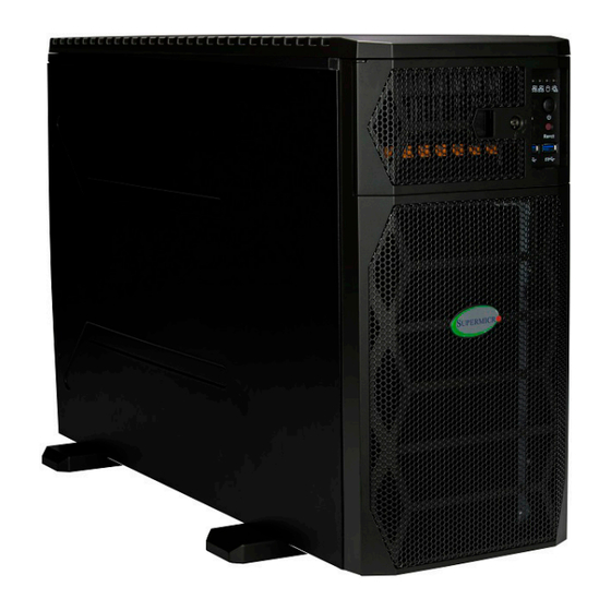
Chapter 1: Introduction 1.2 System Features The following views of the system display the main features. Refer to Appendix B for additional specifications. Front View Top Bezel/ Drive Bays Lower Bezel Covers Liquid Cooling Radiator Figure 1-1. System Front View... - Page 11 Chapter 1: Introduction Control Panel Service/Asset Tag with BMC Password Figure 1-2. Front Storage Drive Logical Numbers Front View Features Item Description Control Panel See the following page for details. Drive Bays Eight 2.5" NVMe/SATA hot-swap storage drive bays Service/Asset Tag Pulls out to reveal a sticker with the unique BMC password...
-
Page 12: Control Panel
Chapter 1: Introduction Control Panel NIC1 NIC2 Drive LED Info LED Power Fail LED Power Button Audio Out Mic In System Reset Figure 1-3. Control Panel Control Panel Features Features Description The main power switch applies or removes primary power from the power supply to the Power Button server but maintains standby power. -
Page 13: Drive Carrier Indicators
Chapter 1: Introduction Information LED Color, Status Description Red, solid An overheating condition has occurred Red, blinking at 1Hz Fan failure, check for an inoperative fan Power failure, check for a non-operational Red, blinking at 0.25Hz power supply Red, blinking at 10Hz CPLD recovery mode error Blue, solid Unit ID has been activated locally... -
Page 14: Rear View
Chapter 1: Introduction Rear View Coolant Level Window Coolant Fill Valve Coolant Drain Valve I/O Panel Power Supplies/ Fans Figure 1-4. System Rear View System Features: Rear Feature Description I/O Panel See the following subsection for details Coolant Level Window Glass window to visually confirm liquid coolant level Coolant Fill/Drain Valves These valves are used to fill or drain the liquid coolant from the system... -
Page 15: Rear Input/Output Panel
Chapter 1: Introduction Expansion Slot Locations Item Description GPU, PCIe 5.0 x16 full-height, 10.5", double width slot (CPU1) GPU, PCIe 5.0 x16 full-height, 10.5", single width slot (CPU1) Not accessible due to DIMM liquid cooling module GPU, PCIe 5.0 x16 full-height, 10.5", single width slot (CPU2) GPU, PCIe 5.0 x16 full-height, 10.5", double width slot (CPU2) PCIe 5.0 x16 full-height, 10.5"... -
Page 16: Liquid Cooling Ports
Indicates that the power supply has a warning condition and continues to operate. Indicates that the power supply is plugged in, and is in an abnormal state. The Amber, Steady system might need service. Please contact Supermicro technical support. No AC power to modules... -
Page 17: Side View, Right
Chapter 1: Introduction Side View, Right Drive Bays Processors and Coldplates Liquid Cooling Radiator DIMM Module GPUs Figure 1-6. System: Right Side View, with Liquid Cooling System Features: Right Side Feature Description Drive Bays Eight bays for storage drives Processors and Dual liquid cooled CPUs Coldplates Liquid Cooling... -
Page 18: Motherboard Layout
Chapter 1: Introduction 1.3 Motherboard Layout Below is a layout of the X13DEG-QT motherboard with jumper, connector and LED locations shown. See the following page for descriptions. For detailed descriptions, pinout information and jumper settings, refer to Chapter 4 or the Motherboard Manual. -
Page 19: Quick Reference
Chapter 1: Introduction Quick Reference Jumper Description Default Setting JBT1 CMOS Clear Open (Normal) JPAC1 Audio Enable Pins 1-2 (Enabled) JPME2 ME Manufacturing Recovery Pins 1-2 (Normal) JVRM1 VRM SMB Clock (to BMC or PCH) Pins 1-2 (BMC, Normal) JVRM2 VRM SMB Data (to BMC or PCH) Pins 1-2 (BMC, Normal) Connector... -
Page 20: Motherboard Block Diagram
Chapter 1: Introduction Connector Description UID-SW Unit Identifier (UID) Switch / BMC Reset Button USB0–USB3 (3.0) Rear I/O USB Ports (USB 3.0) USB4/5 (3.0) Front-accessible USB 3.0 Header with support of two USB 3.0 connections USB6 (3.0) Internal USB 3.0 Vertical Type-A Connector Rear I/O VGA Port Description State: Status... -
Page 21: Processor And Heatsink
Chapter 1: Introduction 1.4 Processor and Heatsink Processor Overview The motherboard supports three versions of the Intel 4th Gen Xeon Scalable processors. They differ in the number of cores, and each requires a different CPU carrier. The XCC version supports up to 60 cores, the MCC version supports up to 32 cores, and the HBM (Xeon Max series) version supports up to 56 cores. -
Page 22: Memory
Product Resources page. Note: Memory DIMM capacities larger than 16 GB are supported under certain conditions, please contact Supermicro Technical Support for additional information about specialized system optimization. DDR5 Memory Support for the Intel 4th Gen Xeon Scalable Processors-SP Speed (MT/s) -
Page 23: Memory Population Guidelines
Chapter 1: Introduction Memory Population Guidelines Use the DIMM slots listed below for memory modules. This memory population table is based on guidelines provided by Intel to support Supermicro motherboards. Memory Population, 16 DIMM Slots, for XCC and MCC CPUs CPUs/DIMMs Memory Population Sequence 2 CPUs &... - Page 24 Chapter 1: Introduction JPAUX1:WOL of onboard LAN 1-2:ENABLE 2-3:DISABLE JPTG1:10Gb LAN 1-2:ENABLE 2-3:DISABLE UID-LED UID-SW COM1 FAN8 USB2/3 (3.0) FANB FAN6 CTRL COM2 BMC_LAN LAN1 LAN2 FAN7 LEDBMC USB0/1 (3.0) JNCSI1 CPU2 JIPMB1 JPFR1 JSTBY1 JRK1 X13DEG-QT REV:1.10 DESIGNED IN USA BIOS LICENSE BAR CODE IPMI CODE...
-
Page 25: Hbm Cpus
Chapter 1: Introduction HBM CPUs The system supports Intel Xeon Max Series CPUs, designed for high bandwidth memory (HBM). Memory Population 16 DIMM Slots, for HBM CPUs CPUs/DIMMs Slots CPU1: A1; CPU2: A1 or 2 CPUs & 2 DIMMs CPU1: E1; CPU2: E1 CPU1: A1, G1;... -
Page 26: Chapter 2 Server Installation
Chapter 2: Server Installation Chapter 2 Server Installation 2.1 Overview Although the CSE-759 chassis is designed to stand vertically by itself, it can be installed optionally in a server rack horizontally. This chapter provides advice and instructions for mounting your system in a server rack. If your system is not already fully integrated with processors, system memory etc., refer to Chapter 3 for details on installing those specific... -
Page 27: Rack Precautions
Chapter 2: Server Installation • This product is not suitable for use with visual display workplace devices according to §2 of the German Ordinance for Work with Visual Display Units. Rack Precautions • Ensure that the leveling jacks on the bottom of the rack are extended to the floor so that the full weight of the rack rests on them. -
Page 28: Airflow
Chapter 2: Server Installation Airflow Equipment should be mounted into a rack so that the amount of airflow required for safe operation is not compromised. Mechanical Loading Equipment should be mounted into a rack so that a hazardous condition does not arise due to uneven mechanical loading. -
Page 29: Installing The Rails
Chapter 2: Server Installation 2.4 Installing the Rails The CSE-759 chassis can be installed in a server rack horizontally. There are a variety of rack units on the market, which may require a slightly different assembly procedure. This rail set fits a rack between 25.6" and 33" deep. The following is a basic guideline for installing the system into a rack with the rack mounting hardware (if provided). - Page 30 Chapter 2: Server Installation Removing the Bottom Stabilizers 1. Remove two screws from the bottom of each stabilizer as shown. Figure 2-2. Bottom Stabilizer Screws Screw Latch (not actually red) Figure 2-3. Bottom Stabilizer Latch and Screw 2. Find the two plastic spring latches on the bottom of the each stabilizer and pull them outward.
-
Page 31: Installing The Inner Rails Onto The Chassis
Chapter 2: Server Installation Installing the Inner Rails onto the Chassis There are two sets of rack rails, one set for the right side of the chassis and one for the left. Each set consists of an inner rail that attaches to the chassis, and an outer rail that attaches to the rack. - Page 32 Chapter 2: Server Installation Handle Handle Figure 2-4. Attaching the Handles 3. Place the inner rail firmly against the side of the chassis, aligning the hooks on the side of the chassis with the holes in the inner rail. 4. Slide the inner rail forward toward the front of the chassis until the quick release bracket snaps into place, securing the rail to the chassis.
-
Page 33: Installing The Outer Rails Onto The Rack
Chapter 2: Server Installation Installing the Outer Rails onto the Rack Installing the Outer Rails 1. Press upward on the locking tab at the rear end of the middle rail. 2. Push the middle rail back into the outer rail. 3. -
Page 34: Installing The System Into A Rack
Chapter 2: Server Installation 2.5 Installing the System into a Rack Once rails are attached to the chassis and the rack, you can install the server. Installing the Chassis into a Rack 1. Extend the outer rails as illustrated above. 2. -
Page 35: Removing The System From The Rack
Chapter 2: Server Installation Removing the System from the Rack Caution! It is dangerous for a single person to off-load the heavy chassis from the rack without assistance. Be sure to have sufficient assistance supporting the chassis when removing it from the rack. -
Page 36: Chapter 3 Maintenance And Component Installation
Chapter 3: Maintenance and Component Installation Chapter 3 Maintenance and Component Installation This chapter provides instructions on installing and replacing main system components. To prevent compatibility issues, only use components that match the specifications and/or part numbers given. Installation or replacement of most components require that power first be removed from the system. -
Page 37: Accessing The System
Chapter 3: Maintenance and Component Installation 3.2 Accessing the System Except for short periods of time, do not operate the workstation without the cover in place. The allows for proper airflow and prevents overheating. Removing the Right Side Chassis Cover 1. -
Page 38: Front Bezel
Chapter 3: Maintenance and Component Installation Removing the Left Side Chassis Cover 1. Remove the three screws at the rear of the cover. 2. Slide the cover back to remove it from the chassis. Front Bezel The front bezel must be removed to change the dust filter. 1. -
Page 39: Motherboard Battery
Chapter 3: Maintenance and Component Installation 3.3 Motherboard Battery The motherboard uses non-volatile memory to retain system information when system power is removed. This memory is powered by a lithium battery residing on the motherboard. Replacing the Battery Begin by removing power from the system. -
Page 40: Storage Drives
Chapter 3: Maintenance and Component Installation 3.4 Storage Drives The system supports up to eight hot-swap 2.5" NVMe or SATA storage drives. Drives are mounted in tool-less carriers that simplify their removal from the chassis. These carriers also help promote proper airflow. For compatible storage drives, see the SYS-751GE-TNRT product page. - Page 41 Chapter 3: Maintenance and Component Installation Removing a Drive Carrier from the Chassis 1. Press the release button on the storage drive carrier, which will extend the handle. 2. Use the carrier handle to pull the drive out of the chassis. Carrier handle Figure 3-6.
-
Page 42: Installing A Drive
Chapter 3: Maintenance and Component Installation Installing a Drive 1. Remove the dummy drive, which comes pre-installed in the drive carrier. Pull out the two locking clasps on the left outside of the carrier and lift out the dummy drive. 2. -
Page 43: Checking The Temperature Of An Nvme Drive
Chapter 3: Maintenance and Component Installation Checking the Temperature of an NVMe Drive There are two ways to check using the BMC Dashboard. Checking a Drive • BMC Dashboard > Server Health > NVMe SSD – Shows the temperatures of all NVMe drives. -
Page 44: System Cooling
Chapter 3: Maintenance and Component Installation 3.5 System Cooling Radiator and Fans Ths SC759 features a closed loop liquid cooling system that includes a storage tank for the liquid coolant, a radiator and two heavy duty fans. This cooling system works by drawing heat from the CPUs, GPUs, and memory using the liquid coolant, pumps, and tubes. -
Page 45: Filling/Draining Liquid Coolant
Chapter 3: Maintenance and Component Installation Filling/Draining Liquid Coolant Over time, the coolant level can decrease. There is a small window to monitor the level. Coolant can be added through the fill valve located on the rear of the chassis. Use the manufacturer qualified coolant irrigation equipment to fill or drain the coolant. -
Page 46: Changing The Dust Filter
Chapter 3: Maintenance and Component Installation Changing the Dust Filter 1. Remove the left side chassis cover. 2. Remove the front bezel. 3. Pop out the dust filter by lifting the plastic latch at the bottom. 4. Snap the new filter into place. 5. -
Page 47: Power Supply
3.6 Power Supply The system features redundant power supplies. The power modules can be changed without powering down the system. New units can be ordered directly from Supermicro or authorized distributors. These power supplies are auto-switching capable. This feature enables them to automatically sense the input voltage and operate at a 100-120v or 180-240v. - Page 48 Chapter 3: Maintenance and Component Installation Push to Release Locking Lever Figure 3-11. Removing the Power Supply...
-
Page 49: Chapter 4 Motherboard Connections
Chapter 4: Motherboard Connections Chapter 4 Motherboard Connections This section describes the jumpers, connections and LEDs on the motherboard and provides pinout definitions. Some connections might not be used in this system. A motherboard layout indicating component locations may be found in Chapter 1. -
Page 50: Power Connections
The JTPM1 header is used to connect a Trusted Platform Module (TPM)/Port 80, which is an option available from Supermicro. A TPM/Port 80 connector is a security device that supports encryption and authentication in hard drives. It allows the motherboard to deny access if the TPM associated with the storage drive is not installed in the system. - Page 51 Note: For detailed instructions on how to configure NIC settings, refer to the Network Interface Card Configuration User's Guide posted on the web page under the link: http://www. supermicro.com/support/manuals/. T-SGPIO Header The Serial General Purpose Input/Output header (T-SGPIO1) is used to communicate with the enclosure management chip on the backplane.
-
Page 52: Standby Power Header
Definition Intrusion Input Ground Inlet Sensor Header This header (JSEN1) allows BMC to monitor thermal inlet temperature. A special module is required. Please contact Supermicro at www.supermicro.com to purchase the module for this header. Inlet Sensor Header Pin Definitions Pin#... -
Page 53: Sata Connectors
Intel PCH C741 chipset. S-SATA0 and S-SATA1 can be used with Supermicro SuperDOMs, which are orange SATA DOM connectors with power pins built in, and do not require external power cables. S-SATA0 and S-SATA1 are compatible with regular... - Page 54 Chapter 4: Motherboard Connections RAID Key Header An Intel VROC RAID Key header is located at JRK1. It supports VMD used in creating optional advanced NVMe RAID configurations. RAID Key Header Pin Definitions Pin# Definition Ground RAID_KEY_PU Ground PCH_RAID_KEY VROC Key Note: This drawing is for illustration only.
-
Page 55: Control Panel
Chapter 4: Motherboard Connections Control Panel JF1 contains header pins for the front control panel connections. All JF1 wires have been bundled into a single cable to simplify this connection. Make sure the red wire plugs into pin 1 as marked on the motherboard. The other end connects to the control panel PCB board. Front Control Panel (JF1) LED Indicators HDD (LED2) LAN Pwr Fail... -
Page 56: Power Button
Chapter 4: Motherboard Connections Power Button The Power On and BMC/BIOS Status LED button is located on Pin 1 and Pin 2 of JF1. Momentarily contacting both pins will power on/off the system or display BMC/BIOS status. Power Button LED Indicator Status Status Event Green: solid on... -
Page 57: Jumpers
Chapter 4: Motherboard Connections 4.4 Jumpers Explanation of Jumpers To modify the operation of the motherboard, jumpers are used to choose between optional settings. Jumpers create shorts between two pins to change the function associated with it. Pin 1 is identified with a square solder pad on the printed circuit board. See the motherboard layout page for jumper locations. - Page 58 Chapter 4: Motherboard Connections ME Recovery JPME2 is used for ME Firmware Recovery mode, which will limit system resource for essential function use only without putting restrictions on power use. In the single operation mode, online upgrade will be available via Recovery mode. ME Recovery Jumper Settings Jumper Setting...
-
Page 59: Led Indicators
Chapter 4: Motherboard Connections 4.5 LED Indicators Network LAN LEDs The Ethernet ports each have two LEDs. One LED indicates activity when flashing green. The other may be solid green, amber or off to indicate the speed of the connection. LAN Link LED Color Definition... -
Page 60: Chapter 5 Software
1. Create a method to access the MS Windows installation ISO file. That can be a USB flash or media drive. 2. Retrieve the proper RST/RSTe driver. Go to the Supermicro web page for your motherboard and click on "Download the Latest Drivers and Utilities", select the proper driver, and copy it to a USB flash drive. - Page 61 Chapter 5: Software 4. During Windows Setup, continue to the dialog where you select the drives on which to install Windows. If the disk you want to use is not listed, click on “Load driver” link at the bottom left corner. Figure 5-2.
-
Page 62: Driver Installation
The Supermicro website contains drivers and utilities for your system at https://www. supermicro.com/wdl/driver. Some of these must be installed, such as the chipset driver. After accessing the website, go into the CDR_Images (in the parent directory of the above link) and locate the ISO file for your motherboard. Download this file to to a USB flash or media drive. -
Page 63: Superdoctor ® 5
5.3 SuperDoctor ® The Supermicro SuperDoctor 5 is a program that functions in a command-line or web-based interface for Windows and Linux operating systems. The program monitors such system health information as CPU temperature, system voltages, system power consumption, fan speed, and provides alerts via email or Simple Network Management Protocol (SNMP). -
Page 64: Bmc
This can be found on a sticker on the chassis and a sticker on the motherboard. The sticker also displays the BMC MAC address. If necessary, the password can be reset using the Supermicro IPMICFG tool. Figure 5-5. BMC Password Label... -
Page 65: Chapter 6 Optional Components
It enables the motherboard to deny access if the TPM associated with the hard drive is not installed in the system. Details and installation procedures are at: http://www.supermicro.com/manuals/other/TPM.pdf. • AOM-TPM-9670V •... -
Page 66: Intel Virtual Raid On Cpu (Vroc)
Chapter 6: Optional Components 6.3 Intel Virtual RAID on CPU (VROC) Intel Virtual RAID on CPU (Intel VROC) is an enterprise RAID solution for NVMe SSDs directly attached to Intel Xeon Scalable processors. Intel Volume Management Device (VMD) is an integrated controller inside the CPU PCIe root complex. -
Page 67: Additional Information
Chapter 6: Optional Components Additional Information Additional information is available on the product page for the Supermicro add-on card and the linked manuals. www.supermicro.com/products/accessories/addon/AOC-VROCxxxMOD.cfm Hardware Key The Intel VROC hardware key is a license key that detects the Intel VROC SKU and activates the function accordingly. -
Page 68: Configuring Intel Vmd
Chapter 6: Optional Components Configuring Intel VMD VMD must be enabled on PCIe ports which have NVMe drives attached to them in order for those drives to be added to a VROC RAID configuration. The default BIOS setting for the NVMe Mode Switch is Auto which automatically enables VMD on all installed NVMe drives. - Page 69 Chapter 6: Optional Components Caution: VMD must only be enabled on NVMe port resources. If VMD is enabled on other PCIe ports, the functionality of those ports will be impacted. See the table below. This table identifies the NVMe Port Resources. Enable VMD on the NVMe drive’s corresponding hardware stack according to the VMD BIOS Settings table.
- Page 70 Chapter 6: Optional Components 4. Select “Intel VMD for Volume Management Device on” on CPU1 or CPU2 to enable VMD for devices under the respective CPU. . Figure 6-3. Intel VMD for Volume Management Device on CPU1 and CPU2 5. Choose Enable for “Enable/Disable VMD” for IOU 0 to list the available devices under IOU 0.
- Page 71 Chapter 6: Optional Components Figure 6-5. BIOS, Enabling VMD on CPU 2 (Example) 6. Enable the NVMe port resource according to table above for the NVMe drives that will be used in a RAID configuration. Figure 6-6. BIOS, Enabling CPU2 (Example) 7.
- Page 72 Chapter 6: Optional Components Figure 6-7. BIOS, Enabling CPU2 Completed (Example) 9. Press [F4] to save the configuration and reboot the system. Note: If there is an existing RAID configuration, delete the RAID volume associated with the VMD controller before disabling the controller. Failure to do so may lead to unexpected behavior.
-
Page 73: Creating Nvme Raid Configurations
Chapter 6: Optional Components Creating NVMe RAID Configurations 1. Open Advanced > Intel(R) Virtual RAID on CPU > All Intel VMD Controllers > Create RAID Volume. Figure 6-8. Created Volume without Figure 6-9. Created Volume with enabling RAID spanned over VMD enabling RAID spanned over VMD controller controller... -
Page 74: Status Indications
Chapter 6: Optional Components Status Indications An LED indicator on the drive carrier shows the RAID status of the drive. Drive Carrier Status LED Indicator Status State (red) Normal function Locating 4 Hz blinking Fault Solid on Rebuilding 1 Hz blinking IBPI SFF 8489 Defined Status LED States Hot Swap Drives Intel VMD enables hot-plug and hot-unplug for NVMe SSDs, whether from Intel or other... -
Page 75: Chapter 7 Troubleshooting And Support
Chapter 7 Troubleshooting and Support 7.1 Information Resources Website A great deal of information is available on the Supermicro website, supermicro.com. Figure 7-1. Supermicro Website • Specifications for servers and other hardware are available by clicking the Products option. •... -
Page 76: Bmc Interface
Security Center for recent security notices Supermicro Phone and Addresses 7.2 BMC Interface The system supports a Baseboard Management Controller (BMC) interface. It provides remote access, monitoring and management. There are several BIOS settings related to the BMC. -
Page 77: Troubleshooting Procedures
Chapter 7: Troubleshooting and Support 7.3 Troubleshooting Procedures JPAUX1:WOL of onboard LAN 1-2:ENABLE 2-3:DISABLE JPTG1:10Gb LAN Use the following procedures to troubleshoot your system. If you have followed all of the 1-2:ENABLE 2-3:DISABLE procedures below and still need assistance, refer to the Technical Support Procedures Returning Merchandise for Service sections in this chapter. -
Page 78: System Boot Failure
• Memory: Make sure that the memory modules are supported. Refer to the product page on our website at www.supermicro.com. Test the modules using memtest86 or a similar utility. • Storage drives: Make sure that all drives work properly. Replace if necessary. - Page 79 Chapter 7: Troubleshooting and Support • Adequate power supply: Make sure that the power supply provides adequate power to the system. Make sure that all power connectors are connected. Refer to the Supermicro website for the minimum power requirements. •...
-
Page 80: Post Codes
7.4 POST Codes The AMI UEFI BIOS supplies checkpoint codes, which are documented online at http://www. supermicro.com/support/manuals/ ("AMI BIOS POST Codes User's Guide"). When BIOS performs the Power On Self Test, it writes checkpoint codes to I/O port 0080h. If the computer cannot complete the boot process, the POST codes can be viewed from the BMC using the Post Snooping function. -
Page 81: Uefi Bios Recovery
Warning: Do not upgrade the BIOS unless your system has a BIOS-related issue. Flashing the wrong BIOS can cause irreparable damage to the system. In no event shall Supermicro be liable for direct, indirect, special, incidental, or consequential damages arising from a BIOS update. - Page 82 USB device or a writable CD/DVD. Note 1: If you cannot locate the "Super.ROM" file in your drive disk, visit our website at www.supermicro.com to download the BIOS package. Extract the BIOS binary image into a USB flash device and rename it "Super.ROM" for the BIOS recovery use.
- Page 83 Chapter 7: Troubleshooting and Support Note: At this point, you may decide if you want to start the BIOS recovery. If you decide to proceed with BIOS recovery, follow the procedures below. 4. When the screen as shown above displays, use the arrow keys to select the item "Proceed with flash update"...
- Page 84 Chapter 7: Troubleshooting and Support 7. Press <Del> continuously during system boot to enter the BIOS Setup utility. From the top of the tool bar, select Boot to enter the submenu. From the submenu list, select Boot Option #1 as shown below. Then, set Boot Option #1 to [UEFI AP:UEFI: Built-in EFI Shell]. Press <F4>...
- Page 85 Chapter 7: Troubleshooting and Support Note: Do not interrupt this process until the BIOS flashing is complete. 9. The screen above indicates that the BIOS update process is complete. When you see the screen above, unplug the AC power cable from the power supply, clear CMOS, and plug the AC power cable in the power supply again to power on the system.
-
Page 86: Cmos Clear
Chapter 7: Troubleshooting and Support 7.7 CMOS Clear JBT1 is used to clear CMOS, which will also clear any passwords. Instead of pins, this jumper consists of contact pads to prevent accidentally clearing the contents of CMOS. To Clear CMOS 1. -
Page 87: Where To Get Replacement Components
7.8 Where to Get Replacement Components If you need replacement parts for your system, to ensure the highest level of professional service and technical support, purchase exclusively from our Supermicro Authorized Distributors/System Integrators/Resellers. A list can be found at: http://www.supermicro.com. -
Page 88: Vendor Support Filing System
For issues related to Red Hat Enterprise Linux, since it is a subscription based OS, contact your account representative. 7.10 Feedback Supermicro values your feedback as we strive to improve our customer experience in all facets of our business. To provide feedback on our manuals, please email us at techwriterteam@... -
Page 89: Contacting Supermicro
San Jose, CA 95131 U.S.A. Tel: +1 (408) 503-8000 Fax: +1 (408) 503-8008 Email: marketing@supermicro.com (General Information) Sales-USA@supermicro.com (Sales Inquiries) Government_Sales-USA@supermicro.com (Gov. Sales Inquiries) support@supermicro.com (Technical Support) RMA@supermicro.com (RMA Support) Webmaster@supermicro.com (Webmaster) Website: www.supermicro.com Europe Address: Super Micro Computer B.V. -
Page 90: Appendix A Standardized Warning Statements For Ac Systems
Supermicro's Technical Support department for assistance. Only certified technicians should attempt to install or configure components. Read this appendix in its entirety before installing or configuring components in the Supermicro chassis. These warnings may also be found on our website at http://www.supermicro.com/about/... - Page 91 Appendix A: Warning Statements Warnung WICHTIGE SICHERHEITSHINWEISE Dieses Warnsymbol bedeutet Gefahr. Sie befinden sich in einer Situation, die zu Verletzungen führen kann. Machen Sie sich vor der Arbeit mit Geräten mit den Gefahren elektrischer Schaltungen und den üblichen Verfahren zur Vorbeugung vor Unfällen vertraut. Suchen Sie mit der am Ende jeder Warnung angegebenen Anweisungsnummer nach der jeweiligen Übersetzung in den übersetzten Sicherheitshinweisen, die zusammen mit diesem Gerät ausgeliefert wurden.
-
Page 92: Installation Instructions
Appendix A: Warning Statements . ٌ ا ك ً ف حالة و ٌ يك أى تتسبب ف اصابة جسذ ة ٌ هذا الزهز ع ٌ خطز !تحذ ز قبل أى تعول عىل أي هعذات،يك عىل علن بالوخاطز ال ا ٌجوة عي الذوائز ٍ... -
Page 93: Circuit Breaker
Appendix A: Warning Statements Warnung Vor dem Anschließen des Systems an die Stromquelle die Installationsanweisungen lesen. ¡Advertencia! Lea las instrucciones de instalación antes de conectar el sistema a la red de alimentación. Attention Avant de brancher le système sur la source d'alimentation, consulter les directives d'installation. .יש... - Page 94 Appendix A: Warning Statements Warnung Dieses Produkt ist darauf angewiesen, dass im Gebäude ein Kurzschluss- bzw. Überstromschutz installiert ist. Stellen Sie sicher, dass der Nennwert der Schutzvorrichtung nicht mehr als: 250 V, 20 A beträgt. ¡Advertencia! Este equipo utiliza el sistema de protección contra cortocircuitos (o sobrecorrientes) del edificio.
-
Page 95: Power Disconnection Warning
Appendix A: Warning Statements Power Disconnection Warning Warning! The system must be disconnected from all sources of power and the power cord removed from the power supply module(s) before accessing the chassis interior to install or remove system components. 電源切断の警告 システムコンポーネントの取り付けまたは取り外しのために、... -
Page 96: Equipment Installation
Appendix A: Warning Statements אזהרה מפני ניתוק חשמלי !אזהרה יש לנתק את המערכת מכל מקורות החשמל ויש להסיר את כבל החשמלי מהספק .לפני גישה לחלק הפנימי של המארז לצורך התקנת או הסרת רכיבים يجب فصم اننظاو من جميع مصادر انطاقت وإ ز انت سهك انكهرباء من وحدة امداد انطاقت... -
Page 97: Restricted Area
Appendix A: Warning Statements ¡Advertencia! Solamente el personal calificado debe instalar, reemplazar o utilizar este equipo. Attention Il est vivement recommandé de confier l'installation, le remplacement et la maintenance de ces équipements à des personnels qualifiés et expérimentés. !אזהרה .צוות מוסמך בלבד רשאי להתקין, להחליף את הציוד או לתת שירות עבור הציוד واملدربيه... - Page 98 Appendix A: Warning Statements Warnung Diese Einheit ist zur Installation in Bereichen mit beschränktem Zutritt vorgesehen. Der Zutritt zu derartigen Bereichen ist nur mit einem Spezialwerkzeug, Schloss und Schlüssel oder einer sonstigen Sicherheitsvorkehrung möglich. ¡Advertencia! Esta unidad ha sido diseñada para instalación en áreas de acceso restringido. Sólo puede obtenerse acceso a una de estas áreas mediante la utilización de una herramienta especial, cerradura con llave u otro medio de seguridad.
-
Page 99: Battery Handling
Appendix A: Warning Statements Battery Handling Warning! There is the danger of explosion if the battery is replaced incorrectly. Replace the battery only with the same or equivalent type recommended by the manufacturer. Dispose of used batteries according to the manufacturer's instructions 電池の取り扱い... -
Page 100: Redundant Power Supplies
Appendix A: Warning Statements هناك خطر من انفجار يف حالة اسحبذال البطارية بطريقة غري صحيحة فعليل اسحبذال البطارية فقط بنفس النىع أو ما يعادلها مام أوصث به الرشمة املصنعة جخلص من البطاريات املسحعملة وفقا لحعليامت الرشمة الصانعة 경고! 배터리가 올바르게 교체되지 않으면 폭발의 위험이 있습니다. 기존 배터리와 동일하거나 제 조사에서... - Page 101 Appendix A: Warning Statements ¡Advertencia! Puede que esta unidad tenga más de una conexión para fuentes de alimentación. Para cortar por completo el suministro de energía, deben desconectarse todas las conexiones. Attention Cette unité peut avoir plus d'une connexion d'alimentation. Pour supprimer toute tension et tout courant électrique de l'unité, toutes les connexions d'alimentation doivent être débranchées.
-
Page 102: Backplane Voltage
Appendix A: Warning Statements Backplane Voltage Warning! Hazardous voltage or energy is present on the backplane when the system is operating. Use caution when servicing. バックプレーンの電圧 システムの稼働中は危険な電圧または電力が、 バックプレーン上にかかっています。 修理する際には注意く ださい。 警告 当系统正在进行时,背板上有很危险的电压或能量,进行维修时务必小心。 警告 當系統正在進行時,背板上有危險的電壓或能量,進行維修時務必小心。 Warnung Wenn das System in Betrieb ist, treten auf der Rückwandplatine gefährliche Spannungen oder Energien auf. -
Page 103: Comply With Local And National Electrical Codes
Appendix A: Warning Statements هناك خطز مه التيار الكهزبايئ أوالطاقة املىجىدة عىل اللىحة عندما يكىن النظام يعمل كه حذ ر ا عند خدمة هذا الجهاس 경고! 시스템이 동작 중일 때 후면판 (Backplane)에는 위험한 전압이나 에너지가 발생 합니다. 서비스 작업 시 주의하십시오. Waarschuwing Een gevaarlijke spanning of energie is aanwezig op de backplane wanneer het systeem in gebruik is. -
Page 104: Product Disposal
Appendix A: Warning Statements תיאום חוקי החשמל הארצי !אזהרה .התקנת הציוד חייבת להיות תואמת לחוקי החשמל המקומיים והארציים تركيب املعدات الكهربائية يجب أن ميتثل للقىاويه املحلية والىطىية املتعلقة بالكهرباء 경고! 현 지역 및 국가의 전기 규정에 따라 장비를 설치해야 합니다. Waarschuwing Bij installatie van de apparatuur moet worden voldaan aan de lokale en nationale elektriciteitsvoorschriften. -
Page 105: Hot Swap Fan Warning
Appendix A: Warning Statements Attention La mise au rebut ou le recyclage de ce produit sont généralement soumis à des lois et/ou directives de respect de l'environnement. Renseignez-vous auprès de l'organisme compétent. סילוק המוצר !אזהרה .סילוק סופי של מוצר זה חייב להיות בהתאם להנחיות וחוקי המדינה التخلص... - Page 106 Appendix A: Warning Statements Warnung Gefährlich Bewegende Teile. Von den bewegenden Lüfterblätter fern halten. Die Lüfter drehen sich u. U. noch, wenn die Lüfterbaugruppe aus dem Chassis genommen wird. Halten Sie Finger, Schraubendreher und andere Gegenstände von den Öffnungen des Lüftergehäuses entfernt.
-
Page 107: Power Cable And Ac Adapter
Verbindungskabeln, Stromkabeln und/oder Adapater, die Ihre örtlichen Sicherheitsstandards einhalten. Der Gebrauch von anderen Kabeln und Adapter können Fehlfunktionen oder Feuer verursachen. Die Richtlinien untersagen das Nutzen von UL oder CAS zertifizierten Kabeln (mit UL/CSA gekennzeichnet), an Geräten oder Produkten die nicht mit Supermicro gekennzeichnet sind. - Page 108 .قيرح وأ لطع يف ببستي دق ىرخأ تالوحمو تالباك يأ مادختسا .ميلسلا سباقلاو لصوملا مجح لبق نم ةدمتعملا تالباكلا مادختسا تادعملاو ةيئابرهكلا ةزهجألل ةمالسلا نوناق رظحيUL وأCSA ( ةمالع لمحت يتلاوUL/CSA) لبق نم ةددحملاو ةينعملا تاجتنملا ريغ ىرخأ تادعم يأ عمSupermicro.
- Page 109 사항을 준수하여 제공되거나 지정된 연결 혹은 구매 케이블, 전원 케이블 및 AC 어댑터를 사용하십시오. 다른 케이블이나 어댑터를 사용하면 오작동이나 화재가 발생할 수 있습니다. 전기 용품 안전법은 UL 또는 CSA 인증 케이블 (코드에 UL / CSA가 표시된 케이블)을 Supermicro 가 지정한 제품 이외의 전기 장치에 사용하는 것을 금지합니다. Stroomkabel en AC-Adapter...
-
Page 110: Appendix B System Specifications
Appendix B: System Specifications Appendix B System Specifications Processors Dual Intel 4th Gen Xeon Scalable processors in Socket E (LGA-4677) with four UPIs (16GT/s max.) with up to 60 CPU cores and TDP up to 270 W Chipset Intel PCH C741 BIOS 256 Mb SPI Flash ROM Memory... - Page 111 Appendix B: System Specifications Operating Environment Operating Temperature: 10º to 25º C (50º to 77º F) Non-operating Temperature: -40º to 60º C (-40º to 140º F) Operating Relative Humidity: 8% to 90% (non-condensing) Non-operating Relative Humidity: 5% to 95% (non-condensing) Note: High TDP CPUs and specific components may be supported under specific conditions.
Need help?
Do you have a question about the SuperWorkstation SYS-751GE-TNRT and is the answer not in the manual?
Questions and answers