Table of Contents
Advertisement
Quick Links
Advertisement
Table of Contents

Subscribe to Our Youtube Channel
Related Manuals for Supermicro SuperWorkstation 7049A-T


Summary of Contents for Supermicro SuperWorkstation 7049A-T
- Page 1 SuperWorkstation ® 7049A-T USER’S MANUAL Revision 2.0a...
- Page 2 State of California, USA. The State of California, County of Santa Clara shall be the exclusive venue for the resolution of any such disputes. Supermicro's total liability for all claims will not exceed the price paid for the hardware product.
- Page 3 About this Manual This manual is written for professional system integrators and PC technicians. It provides information for the installation and use of the SuperWorkstation 7049A-T. Installation and maintenance should be performed by experienced technicians only. Please refer to the 7049A-T server specifications page on our website for updates on supported memory, processors and operating systems (http://www.supermicro.com).
-
Page 4: Table Of Contents
Preface Contents Chapter 1 Introduction 1.1 Overview ..........................8 1.2 Unpacking the System ......................8 1.3 System Features ........................9 1.4 Server Chassis Features ....................10 Control Panel ........................10 Front Features ........................11 Rear Features ........................12 1.5 Motherboard Layout ......................13 Quick Reference Table ......................14 Chapter 2 Server Installation 2.1 Overview ..........................17 2.2 Preparing for Setup ......................17 Choosing a Setup Location ....................17... - Page 5 SuperWorkstation 7049A-T User's Manual The Xeon Scalable Processor ..................26 Assembling the Processor Package ................26 Assembling the Processor Heatsink Module (PHM) .............28 Removing the Dust Cover from the CPU Socket ............29 Installing the Processor Heatsink Module (PHM) ............29 Removing the Processor Heatsink Module from the Motherboard .......30 Memory Support ........................31...
- Page 6 Preface Explanation of Jumpers ....................52 4.5 LED Indicators ........................54 Chapter 5 Software 5.1 Microsoft Windows OS Installation ..................56 5.2 Driver Installation ........................58 5.3 SuperDoctor 5 ........................59 ® 5.4 IPMI ............................59 Chapter 6 BIOS 6.1 Introduction .........................60 6.2 Main Setup .........................61 6.3 Advanced Setup Configurations ..................63 6.5 IPMI ...........................
- Page 7 SuperWorkstation 7049A-T User's Manual Contacting Supermicro Headquarters Address: Super Micro Computer, Inc. 980 Rock Ave. San Jose, CA 95131 U.S.A. Tel: +1 (408) 503-8000 Fax: +1 (408) 503-8008 Email: marketing@supermicro.com (General Information) support@supermicro.com (Technical Support) Website: www.supermicro.com Europe Address: Super Micro Computer B.V.
-
Page 8: Overview
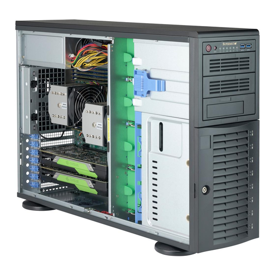
SuperWorkstation 7049A-T User's Manual Chapter 1 Introduction 1.1 Overview This chapter provides a brief outline of the functions and features of the 7049A-T SuperWorkstation. The 7049A-T is based on the X11DAi-N motherboard and the SC743TS-1200BP-SQ chassis. In addition to the motherboard and chassis, several important parts that are included with the system are listed below. -
Page 9: System Features
Chapter 1: Introduction 1.3 System Features The following table provides you with an overview of the main features of the 7049A-T. Please refer to Appendix C for additional specifications. System Features Motherboard X11DAi-N Chassis SC743TS-1200BP-SQ Dual Intel Xeon 81xx/61xx/51xx/41xx/31xx Series processors Socket Type Memory Up to 2048 GB of 3DS RDIMM/3DS LRDIMM/LRDIMM/RDIMM DDR4 ECC 2666/2400/2133 MHz memory in 16... -
Page 10: Server Chassis Features
SuperWorkstation 7049A-T User's Manual 1.4 Server Chassis Features Control Panel The switches and LEDs located on the control panel are described below. See Chapter 4 for details on the control panel connections. Figure 1-1. Control Panel View Control Panel Features... -
Page 11: Front Features
Chapter 1: Introduction Front Features The SC743TS-1200BP-SQ is a 4U chassis See the illustration below for the features included on the front of the chassis. Figure 1-2. Chassis Front View Front Chassis Features Item Feature Description Control Panel See previous page for details 5.25"... -
Page 12: Rear Features
SuperWorkstation 7049A-T User's Manual Rear Features The illustration below shows the features included on the rear of the chassis. Figure 1-3. Chassis Rear View Rear Chassis Features Item Feature Description Power Supply Single 1200W power supply (p/n PWS-1K25P-PQ) 9-cm Super Quiet exhaust fan Rear I/O Ports See section 4.3 for details... -
Page 13: Motherboard Layout
Chapter 1: Introduction 1.5 Motherboard Layout Below is a layout of the X11DAi-N with jumper, connector and LED locations shown. See the table on the following page for descriptions. For detailed descriptions, pinout information and jumper settings, refer to Chapter 4. USB8/9 (3.1) AUDIO... -
Page 14: Quick Reference Table
SuperWorkstation 7049A-T User's Manual Quick Reference Table Jumper Description Default Setting JBT1 CMOS Clear Open (Normal) JPG1 VGA Enable/Disable Pins 1-2 (Enabled) JPME1 ME Recovery Pins 1-2 (Normal) JPME2 Manufacturing Mode Select Pins 1-2 (Normal) JVRM1 VRM SMB Clock to BMC... - Page 15 Chapter 1: Introduction Connector Description General Purpose Serial I/O ports 1/2/3 (T-SGPIO1: SATA1~4, T-SGPIO2: SATA5~8, T-SGPIO3: T-SGPIO1/2/3 S-SATA1/2) USB1/2/3/4 (3.0) Backpanel USB 3.0 ports 1/2/3/4 USB7 (3.0) Front Accessible USB 3.0 Type A connector (USB 7) USB5/6 (3.0) USB 3.0 connections 5/6 for front access USB8/9 (3.1) Back panel USB 3.1 ports 8/9 VGA port on the I/O back panel...
- Page 16 SuperWorkstation 7049A-T User's Manual X11DAI-N Block Diagram #1-8 #2-8 #1-7 #2-7 #1-6 #2-6 #1-5 #2-5 #1-4 #2-4 #1-3 #2-3 #1-2 #2-2 #1-1 #2-1 SNB CORE SNB CORE : I C DDR4 DDR4 #3AB DMI3 DMI2 PCI-E X16 G3 PCI-E X16 G3...
-
Page 17: Chapter 2 Server Installation
Chapter 2: Server Installation Chapter 2 Server Installation 2.1 Overview This chapter provides advice and instructions for mounting your system in a server rack. If your system is not already fully integrated with processors, system memory etc., refer to Chapter 4 for details on installing those specific components. Caution: Electrostatic Discharge (ESD) can damage electronic components. -
Page 18: Server Precautions
SuperWorkstation 7049A-T User's Manual • In single rack installations, stabilizers should be attached to the rack. In multiple rack in- stallations, the racks should be coupled together. • Always make sure the rack is stable before extending a server or other component from the rack. -
Page 19: Circuit Overloading
Chapter 2: Server Installation Circuit Overloading Consideration should be given to the connection of the equipment to the power supply circuitry and the effect that any possible overloading of circuits might have on overcurrent protection and power supply wiring. Appropriate consideration of equipment nameplate ratings should be used when addressing this concern. -
Page 20: Installing The System Into A Rack
SuperWorkstation 7049A-T User's Manual 2.3 Installing the System into a Rack This section provides information on installing the system into a rack unit. Rack installation requires the use of the optional rackmount kit. There are a variety of rack units on the market, which may mean the assembly procedure will differ slightly. -
Page 21: Installing The Rack Rails
Figure 2-1. Preparing to Install the Chassis Rails Installing the Rack Rails Determine where you want to place the SuperWorkstation 7049A-T in the rack. (See Rack and Server Precautions in Section 2-3.) Position the fixed rack rail/sliding rail guide assemblies at the desired location in the rack, keeping the sliding rail guide facing the inside of the rack. - Page 22 SuperWorkstation 7049A-T User's Manual Figure 2-2. Installing the Rails to the Chassis Warning: Stability hazard. The rack stabilizing mechanism must be in place, or the rack must be bolted to the floor before you slide the unit out for servicing. Failure to...
-
Page 23: Installing The System Into The Rack
Chapter 2: Server Installation Installing the System into the Rack You should now have rails attached to both the chassis and the rack unit. The next step is to install the system into the rack. You should have two brackets in the rack mount kit. Install these first keeping in mind that they are left/right specific (marked with "L"... -
Page 24: Chapter 3 Maintenance And Component Installation
SuperWorkstation 7049A-T User's Manual Chapter 3 Maintenance and Component Installation This chapter provides instructions on installing and replacing main system components. To prevent compatibility issues, only use components that match the specifications and/or part numbers given. Installation or replacement of most components require that power first be removed from the system. -
Page 25: Motherboard Components
Check that the plastic socket dust cover is in place and none of the socket pins are bent— otherwise, contact your retailer. • Refer to the Supermicro website for updates on CPU support. • Graphics in this manual are for illustration. Your components may look slightly different. -
Page 26: The Xeon Scalable Processor
SuperWorkstation 7049A-T User's Manual The Xeon Scalable Processor Non-F model Processor F model Processor Figure 3-1. Xeon Scalable Processors Assembling the Processor Package Attach the processor to the thin processor clip to create the processor package. 1. On the top corner of the CPU, locate pin 1 (A), marked by a triangle. Also, locate notch B and notch C (and notch D for F models) on the CPU as shown below. - Page 27 Chapter 3: Maintenance and Component Installation CPU (Upside Down) Align Notch C of the CPU w/CPU LGA Lands up and Notch C of the Processor Clip Pin 1 Allow Notch C to latch on to CPU Align Notch B of the CPU and Notch B of the Processor Clip CPU/Heatsink Package (Upside Down)
-
Page 28: Assembling The Processor Heatsink Module (Phm)
SuperWorkstation 7049A-T User's Manual Assembling the Processor Heatsink Module (PHM) After creating the processor package assembly, mount it onto the heatsink to create the processor heatsink module (PHM). 1. On the heatsink label, locate "1" and the corner next to it. Turn the heatsink upside down with the thermal grease side facing up, keeping track of the "1"... -
Page 29: Removing The Dust Cover From The Cpu Socket
Chapter 3: Maintenance and Component Installation Non-Fabric CPU and Processor Clip (Upside Down) Triangle on the CPU Triangle on the Processor Clip Heatsink (Upside Down) On Locations of (C, D), the notches snap onto the heat sink’s Removing the Dust Cover from the CPU Socket mounting holes Remove the dust cover from the CPU socket, exposing the socket pins as shown below. -
Page 30: Removing The Processor Heatsink Module From The Motherboard
SuperWorkstation 7049A-T User's Manual 3. Align the two holes at diagonal corners of the PHM onto the two guide posts on the socket bracket and carefully lower the PHM onto the socket. 4. Use a T30 Torx-bit screwdriver to install four screws into the mounting holes on the socket to securely attach the PHM onto the motherboard in the sequence of 1, 2, 3, and 4, as marked on the heatsink label. -
Page 31: Memory Support
Chapter 3: Maintenance and Component Installation Removing the screws in the sequence of 4, 3, 2, 1 CPU Socket After removing the screws, lift the Processor Heatsink Printed Triangle on Motherboard Module off the CPU socket. Figure 3-7. Removing the Processor Heatsink Module Memory Support The X11DAi-N supports up to 2048 GB of 3DS RDIMM/3DS LRDIMM/LRDIMM/RDIMM DDR4 ECC 2666/2400/2133 MHz memory in 16 memory slots. - Page 32 2666 DRx4 16 GB 32 GB 2666 QRX4 2H-64GB 2666 RDIMM 3Ds 8RX4 4H-128GB 2666 LRDIMM QRx4 32 GB 64 GB 2666 QRX4 2H-64GB 2666 LRDIMM 8Rx4 4H-128 GB 2666 Check the Supermicro website for possible updates to memory support.
-
Page 33: Memory Population Guidelines
Then, if using two DIMMs per channel, install the second DIMM in the black slot. The following memory population sequence table was created based on guidelines provided by Intel to support Supermicro motherboards. The diagram is for illustrative purposes; your motherboard may look different. - Page 34 SuperWorkstation 7049A-T User's Manual Memory Population for X11 DP Motherboard, 16 DIMM Slots When 1 CPU is used: Memory Population Sequence 1 CPU & 1 DIMM CPU1: P1-DIMMA1 1 CPU & 2 DIMMs CPU1: P1-DIMMA1/P1-DIMMD1 1 CPU & 3 DIMMs CPU1: P1-DIMMC1/P1-DIMMB1/P1-DIMMA1 1 CPU &...
- Page 35 Chapter 3: Maintenance and Component Installation CPU2 CPU1...
-
Page 36: Installing Memory
SuperWorkstation 7049A-T User's Manual Installing Memory Insert DIMM modules in the following order: For CPU1, begin with P1-DIMMA1, P1-DIMMD1, then P1-DIMMB1, P1-DIMME1. For CPU2, begin with P2-DIMMA1, P2-DIMMD1, then P2- DIMMB1, P2-DIMME1 For the system to work properly, please use memory modules of the same type and speed. -
Page 37: Pci Expansion Card Installation
Chapter 3: Maintenance and Component Installation PCI Expansion Card Installation The 7049A-T can accommodate standard size add-on cards populated in all slots on the X11DAi-N serverboard. Installing PCI Expansion Cards Begin by removing power from the system as described in section 3.1. 1. -
Page 38: Chassis Components
SuperWorkstation 7049A-T User's Manual 3.4 Chassis Components Hard Drives A total of eight SATA drives may be housed in the SC743TS-1200BP-SQ chassis. The drive IDs are preconfigured as 0 through 7 in order from bottom to top (or from left to right if rackmounted). -
Page 39: Sata Backplane
Chapter 3: Maintenance and Component Installation Figure 3-11. Mounting a Drive in a Carrier Note: Enterprise level hard disk drives are recommended for use in Supermicro chassis and servers. For information on recommended HDDs, visit the Supermicro website at http://www. -
Page 40: System Fans
Installing a New Fan 1. Replace the failed fan with an identical one (available from Supermicro) 2. Install it in the same position and orientation as the one you removed; it should click into place when fully inserted. - Page 41 Chapter 3: Maintenance and Component Installation Figure 3-12. Removing/Replacing a System Fan...
-
Page 42: Power Supply
SuperWorkstation 7049A-T User's Manual Power Supply The SuperWorkstation 7049A-T has a single 1200 watt power supply. This power unit is equipped with low-noise technology, making the system ideal for workstation environments. The power supply has an auto-switching capability that enable it to automatically sense and operate with 100 or 240 volt inputs. -
Page 43: Chapter 4 Motherboard Connections
Chapter 4: Motherboard Connections Chapter 4 Motherboard Connections This section describes the connections on the motherboard and provides pinout definitions. Note that depending on how the system is configured, not all connections are required. The LEDs on the motherboard are also described here. A serverboard layout indicating component locations may be found in Chapter 1. -
Page 44: Headers And Connectors
SuperWorkstation 7049A-T User's Manual 12V 8-pin CPU Power Connectors JPWR1 and JPWR2 are the 8-pin 12V DC power input for the CPU or alternative single power source for a special enclosure when the 24-pin ATX power is not in use. Refer to the table below for pin definitions. - Page 45 Chapter 4: Motherboard Connections SPDIF_In/ SPDIF_Out Headers The SPDIF_In (JSPDIF_In) and SPDIF_Out (JSPDIF_Out) headers are located next to PCI-E Slot 5 on the motherboard. Place a cap on each header for audio support. You will also need to have a cable to use each connection. SPDIF_In SPDIF_Out Pin Definitions...
- Page 46 SuperWorkstation 7049A-T User's Manual Power SMB (I C) Header The Power System Management Bus (I C) connector (JPI C1) monitors the power supply, fan, and system temperatures. Refer to the table below for pin definitions. Power SMB Header Pin Definitions...
-
Page 47: Control Panel
Chapter 4: Motherboard Connections NVMe I C 1/2 Headers Connector JNVI C1/2 are management headers for the Supermicro AOC NVMe PCI-E peripheral cards. Please connect the I C cables to these connectors for system management support. NVMe Slots Use these two NVMe slots (JNVME1 and JNVME2) for high-speed PCI-E storage device support. - Page 48 SuperWorkstation 7049A-T User's Manual Reset Button The Reset Button connection is located on pins 3 and 4 of JF1. Attach it to a hardware reset switch on the computer case to reset the system. Reset Button Pin Definitions (JF1) Pins...
-
Page 49: Ports
The X11DAi-N has eight SATA 3.0 ports (SATA1-4, 5-8) supported by the Intel PCHC620 and two S-SATA (S-SATA1/2) supported by the Intel SCU. S-SATA1/2 can be used with Supermicro SuperDOMs, which are yellow SATA DOM connectors with power pins built in, and do not require external power cables. -
Page 50: Rear I/O Ports
SuperWorkstation 7049A-T User's Manual Front Accessible Audio Header A 10-pin audio header, located next to PCI-E Slot 1, allows you to use the onboard sound for audio playback. Connect an audio cable to the audio header to use this feature. - Page 51 Chapter 4: Motherboard Connections 7.1 HD (High-Definition) Audio This motherboard features a 7.1 Channel High-Definition Audio (HDA) codec that provides 8 DAC channels. The HD audio supports multiple-streaming 7.1 sound playback through the front_panel stereo output via the subwoofer speakers. Download the appropriate software from our website to enable this function.
-
Page 52: Jumpers
SuperWorkstation 7049A-T User's Manual 4.4 Jumpers Explanation of Jumpers To modify the operation of the motherboard, jumpers are used to choose between optional settings. Jumpers create shorts between two pins to change the function associated with it. Pin 1 is identified with a square solder pad on the printed circuit board. See the motherboard layout page for jumper locations. - Page 53 Chapter 4: Motherboard Connections VGA Enable/Disable JPG1 allows you to enable or disable the VGA port using the onboard graphics controller. The default setting is Enabled. VGA Enable/Disable Jumper Settings Jumper Setting Definition Pins 1-2 Enabled Pins 2-3 Disabled Management Engine (ME) Recovery Use jumper JPME1 to select ME Firmware Recovery mode, which will limit resource allocation for essential system operation only in order to maintain normal power operation and management.
-
Page 54: Led Indicators
SuperWorkstation 7049A-T User's Manual C Bus for VRM Jumpers JVRM1 and JVRM2 allow the VRM SMB Clock and Data to access the Baseboard Management Controller (BMC). JVRM1 (VRM SMB Clock to BMC) Jumper Settings Jumper Setting Definition Pins 1-2 Enable... - Page 55 Chapter 4: Motherboard Connections BMC Heartbeat LED LEDM1 is the BMC heartbeat LED. When the LED is blinking green, BMC is functioning normally. Onboard Power LED Indicator LED Color Definition Green: BMC Normal Blinking Onboard Power LED The Onboard Power LED is located at LE2 on the motherboard. When this LED is on, the system is on.
-
Page 56: Chapter 5 Software
USB/SATA DVD drive, or a USB flash drive, or the IPMI KVM console. 2. Retrieve the proper RST/RSTe driver. Go to the Supermicro web page for your motherboard and click on "Download the Latest Drivers and Utilities", select the proper driver, and copy it to a USB flash drive. - Page 57 Chapter 5: Software 4. During Windows Setup, continue to the dialog where you select the drives on which to install Windows. If the disk you want to use is not listed, click on “Load driver” link at the bottom left corner. Figure 5-2.
-
Page 58: Driver Installation
The Supermicro website contains drivers and utilities for your system at https://www. supermicro.com/wftp/driver. Some of these must be installed, such as the chipset driver. After accessing the website, go into the CDR_Images (in the parent directory of the above link) and locate the ISO file for your motherboard. Download this file to create a DVD of the drivers and utilities it contains. -
Page 59: Superdoctor ® 5
5.3 SuperDoctor ® The Supermicro SuperDoctor 5 is a program that functions in a command-line or web-based interface for Windows and Linux operating systems. The program monitors such system health information as CPU temperature, system voltages, system power consumption, fan speed, and provides alerts via email or Simple Network Management Protocol (SNMP). -
Page 60: Chapter 6 Bios
SuperWorkstation 7049A-T User's Manual Chapter 6 BIOS 6.1 Introduction This chapter describes the AMIBIOS™ Setup utility for the motherboard. The BIOS is stored on a chip and can be easily upgraded using a flash program. Note: Due to periodic changes to the BIOS, some settings may have been added or deleted and might not yet be recorded in this manual. -
Page 61: Main Setup
Note: The time is in the 24-hour format. For example, 5:30 P.M. appears as 17:30:00. The date's default value is 01/01/2015 after RTC reset. Supermicro X11DAi-N BIOS Version This item displays the version of the BIOS ROM used in the system. - Page 62 SuperWorkstation 7049A-T User's Manual Memory Information Total Memory This item displays the total size of memory available in the system.
-
Page 63: Advanced Setup Configurations
Chapter 6: BIOS 6.3 Advanced Setup Configurations Use the arrow keys to select Boot Setup and press <Enter> to access the submenu items. Warning: Take caution when changing the Advanced settings. An incorrect value, a very high DRAM frequency, or an incorrect DRAM timing setting may make the system unstable. When this occurs, revert to the default to the manufacture default settings. - Page 64 SuperWorkstation 7049A-T User's Manual Wait For "F1" If Error Use this feature to force the system to wait until the 'F1' key is pressed if an error occurs. The options are Disabled and Enabled. INT19 (Interrupt 19) Trap Response Interrupt 19 is the software interrupt that handles the boot disk function. When this item is set to Immediate, the ROM BIOS of the host adaptors will "capture"...
- Page 65 Chapter 6: BIOS CPU Configuration Processor Configuration The following CPU information will display: • Processor BSP Revision • Processor Socket • Processor ID • Processor Frequency • Processor Max Ratio • Processor Min Ratio • Microcode Revision • L1 Cache RAM •...
- Page 66 SuperWorkstation 7049A-T User's Manual PPIN Control Select Unlock/Enable to use the Protected-Processor Inventory Number (PPIN) in the system. The options are Unlock/Disable and Unlock/EnablE Hardware Prefetcher (Available when supported by the CPU) If set to Enabled, the hardware prefetcher will prefetch streams of data and instructions from the main memory to the L2 cache to improve CPU performance.
- Page 67 Chapter 6: BIOS Speedstep (Pstates) Intel SpeedStep Technology allows the system to automatically adjust processor voltage and core frequency to reduce power consumption and heat dissipation. The options are Disabled and Enabled. EIST PSD Funtion This feature allows the user to choose between Hardware and Software to control the processor's frequency and performance (P-state).
- Page 68 SuperWorkstation 7049A-T User's Manual Package C State Control Package C State This feature allows the user to set the limit on the C State package register. The options are C0/C1 State, C2 State, C6 (Non Retention) State, C6 (Retention) state, No Limit, and Auto.
- Page 69 Chapter 6: BIOS Degrade Precedence Use this feature to set degrade precedence when system settings are in conflict. Select Topology Precedence to degrade Features. Select Feature Precedence to degrade Topology. The options are Topology Precedence and Feature Precedence. Link L0p Enable Select Enable for Link L0p support.
- Page 70 SuperWorkstation 7049A-T User's Manual Memory Topology This feature displays DIMM population information. Memory RAS Configuration Static Virtual Lockstep Mode Select Enable to run the system's memory channels in lockstep mode to minimize memory access latency. The options are Disable and Enable.
- Page 71 Chapter 6: BIOS Patrol Scrub Interval This feature allows you to decide how many hours the system should wait before the next complete patrol scrub is performed. Use the keyboard to enter a value from 0-24. The default setting is 24. IIO Configuration ...
- Page 72 SuperWorkstation 7049A-T User's Manual PCI-E Port Max Payload Size Selecting Auto for this feature will enable the motherboard to automatically detect the maximum Transaction Layer Packet (TLP) size for the connected PCI-E device, allowing for maximum I/O efficiency. Selecting 128B or 256B will designate maximum packet size of 128 or 256.
- Page 73 Chapter 6: BIOS Use this feature to enable Non-Isoch VT-d Engine Address Translation Services (ATS) support. ATS translates virtual addresses to physical addresses. The options are Enable and Disable. Posted Interrupt Use this feature to enable VT_D Posted Interrupt. The options are Enable and Disable. Coherency Support (Non-Isoch) Use this feature to maintain setting coherency between processors or other devices.
- Page 74 SuperWorkstation 7049A-T User's Manual Port 60/64 Emulation This feature allows legacy I/O support for USB devices like mice and keyboards. The options are Enabled and disabled. Default setting is Enabled. Port 61h bit-4 Emulation Select Enabled to enable the emulation of Port 61h but-4 toggling in SMM (System Management Mode).
- Page 75 Chapter 6: BIOS Configure SATA as Select IDE to configure a SATA drive specified by the user as an IDE drive. Select AHCI to configure a SATA drive specified by the user as an AHCI drive. Select RAID to configure a SATA drive specified by the user as a RAID drive.
- Page 76 SuperWorkstation 7049A-T User's Manual sSATA Configuration When this submenu is selected, the AMI BIOS automatically detects the presence of the SATA devices that are supported by the Intel PCH chip and displays the following items: sSATA Controller This item enables or disables the onboard sSATA controller supported by the Intel PCH chip.
- Page 77 Chapter 6: BIOS Port 0 ~ Port 2 Spin Up Device On an edge detect from 0 to 1, set this item to allow the PCH to initialize the device. The options are Disabled and Enabled. Port 0 ~ Port 2 SsATA Device Type Use this item to specify if the SATA port specified by the user should be connected to a Solid State drive or a Hard Disk Drive.
- Page 78 SuperWorkstation 7049A-T User's Manual Maximum Read Request Select Auto for the system BIOS to automatically set the maximum size for a read request for a PCI-E device to enhance system performance. The options are Auto, 128 Bytes, 256 Bytes, 512 Bytes, 1024 Bytes, 2048 Bytes, and 4096 Bytes.
- Page 79 Chapter 6: BIOS CPU SLOT4 PCI-E 3.0 X8 OPROM Use this feature to select which firmware type to be loaded for the add-on card in this slot. The options are Disabled, Legacy, and EFI. CPU SLOT5 PCI-E 3.0 X16 OPROM Use this feature to select which firmware type to be loaded for the add-on card in this slot.
- Page 80 SuperWorkstation 7049A-T User's Manual Ipv6 PXE Support Use this feature to enable Ipv6 PXE Boot Support. If this feature is disabled, it will not create the Ipv6 PXE Boot option. The options are Disabled and Enabled. Ipv6 HTTP Support Use this feature to enable Ipv6 HTTP Boot Support. If this feature is disabled, it will not create the Ipv6 HTTP Boot option.
- Page 81 Chapter 6: BIOS Serial Port 2 Attribute Select SOL to use COM Port 2 as a Serial_Over_LAN (SOL) port for console redirectoin. The options are COM and SOL. Serial Port Console Redirection COM0 Console Redirection Select Enabled to enable console redirection support for a serial port specified by the user. The options are Enabled and Disabled.
- Page 82 SuperWorkstation 7049A-T User's Manual Stop Bits A stop bit indicates the end of a serial data packet. Select 1 Stop Bit for standard serial data communication. Select 2 Stop Bits if slower devices are used. The options are 1 and 2.
- Page 83 Chapter 6: BIOS Legacy Console Redirection Settings Legacy Serial Redirection Port Use this feature to select a COM port to display redirection of Legacy OS and Legacy OPROM messages. The options are COM1 and SOL/COM2. EMS Console Redirection Settings EMS Console Redirection This feature allows the user to specify how the host computer will exchange data with the client computer, which is the remote computer used by the user.
- Page 84 SuperWorkstation 7049A-T User's Manual Odd if the parity bit is set to 0, and the number of 1's in data bits is odd. Select None if you do not want to send a parity bit with your data bits in transmission. Select Mark to add a mark as a parity bit to be sent along with the data bits.
- Page 85 Chapter 6: BIOS Current Status Information TXT Support Intel TXT (Trusted Execution Technology) helps protect against software-based atacks and ensures protection, confidentiality and integrity of data sotred or created on the system. Use this feature to enable to disable TXT Suppport. The options are Disabled and Enabled.
- Page 86 SuperWorkstation 7049A-T User's Manual 6.4 Event Logs Use this feature to configure Event Log settings. Change SMBIOS Event Log Settings Enabling/Disabling Options SMBIOS Event Log Change this item to enable or disable all features of the SMBIOS Event Logging during system boot.
- Page 87 Chapter 6: BIOS Log System Boot Event This option toggles the System Boot Event logging to enabled or disabled. The options are Disabled and Enabled. MECI The Multiple Event Count Increment (MECI) counter counts the number of occurences that a duplicate event must happen before the MECI counter is incremented. This is a numeric value.
-
Page 88: Ipmi
SuperWorkstation 7049A-T User's Manual 6.5 IPMI Use this feature to configure Intelligent Platform Management Interface (IPMI) settings. BMC Firmware Revision This item indicates the IPMI firmware revision used in your system. IPMI Status (Baseboard Management Controller) This item indicates the status of the IPMI firmware installed in your system. - Page 89 Chapter 6: BIOS When SEL is Full This feature allows the user to decide what the BIOS should do when the system event log is full. Select Erase Immediately to erase all events in the log when the system event log is full.
- Page 90 SuperWorkstation 7049A-T User's Manual Station IP Address This item displays the Station IP address for this computer. This should be in decimal and in dotted quad form (i.e., 192.168.10.253). Subnet Mask This item displays the sub-network that this computer belongs to. The value of each three- digit number separated by dots should not exceed 255.
- Page 91 Chapter 6: BIOS 6.6 Security This menu allows the user to configure the following security settings for the system. Administrator Password Press Enter to create a new, or change an existing Administrator password. User Password Press Enter to create a new, or change an existing User password. Password Check Select Setup for the system to check for a password at Setup.
- Page 92 SuperWorkstation 7049A-T User's Manual Secure Boot Use this item to enable secure boot. The options are Disabled and Enabled. CSM Support Select Enabled to support the EFI Compatibility Support Module (CSM), which provides compatibility support for traditional legacy BIOS for system boot. The options are Enabled and Disabled.
- Page 93 Chapter 6: BIOS Append Key Select Yes to add the database from the manufacturer's defaults to the existing DB. Select No to load the DB from a file. The options are Yes and No. Forbiden Signatures Set New Key Select Yes to load the DBX from the manufacturer's defaults.
-
Page 94: Boot
SuperWorkstation 7049A-T User's Manual To set this feature, select Restore User Defaults from the Exit menu and press <Enter>. Use this feature to retrieve user-defined settings that were saved previously. 6.7 Boot Use this feature to configure Boot settings. Boot Mode Select Use this item to select the type of device that the system is going to boot from. - Page 95 Chapter 6: BIOS • Legacy/UEFI/Dual Boot Option #3 • Legacy/UEFI/Dual Boot Option #4 • Legacy/UEFI/Dual Boot Option #5 • Legacy/UEFI/Dual Boot Option #6 • Legacy/UEFI/Dual Boot Option #7 • Legacy/UEFI/Dual Boot Option #8 • Legacy/UEFI/Dual Boot Option #9 • Legacy/UEFI/Dual Boot Option #10 •...
- Page 96 SuperWorkstation 7049A-T User's Manual Path for Boot Option Use this item to enter the path for the new boot option in the format fsx:\path\filename.efi. Boot Option File Path Use this item to specify the file path for the new boot option.
-
Page 97: Save & Exit
Chapter 6: BIOS 6.8 Save & Exit Select the Save & Exit tab from the BIOS setup screen to configure the settings below: Save Options Discard Changes and Exit Select this option to quit the BIOS Setup without making any permanent changes to the system configuration, and reboot the computer. - Page 98 SuperWorkstation 7049A-T User's Manual Default Options Restore Defaults To set this feature, select Restore Defaults from the Save & Exit menu and press <Enter>. These are factory settings designed for maximum system stability, but not for maximum performance. Save As User Defaults To set this feature, select Save as User Defaults from the Save &...
-
Page 99: Appendix A Bios Codes
Appendix A: BIOS Codes Appendix A BIOS Codes A.1 BIOS Error POST (Beep) Codes During the POST (Power-On Self-Test) routines, which are performed each time the system is powered on, errors may occur. Non-fatal errors are those which, in most cases, allow the system to continue the boot-up process. - Page 100 When BIOS performs the Power On Self Test, it writes checkpoint codes to I/O port 0080h. If the computer cannot complete the boot process, a diagnostic card can be attached to the computer to read I/O port 0080h (Supermicro p/n AOC-LPC80-20). For information on AMI updates, please refer to http://www.ami.com/products/.
-
Page 101: Appendix B Standardized Warning Statements For Ac Systems
Supermicro's Technical Support department for assistance. Only certified technicians should attempt to install or configure components. Read this appendix in its entirety before installing or configuring components in the Supermicro chassis. These warnings may also be found on our website at http://www.supermicro.com/about/... - Page 102 Appendix B: Standardized Warning Statements Warnung WICHTIGE SICHERHEITSHINWEISE Dieses Warnsymbol bedeutet Gefahr. Sie befinden sich in einer Situation, die zu Verletzungen führen kann. Machen Sie sich vor der Arbeit mit Geräten mit den Gefahren elektrischer Schaltungen und den üblichen Verfahren zur Vorbeugung vor Unfällen vertraut. Suchen Sie mit der am Ende jeder Warnung angegebenen Anweisungsnummer nach der jeweiligen Übersetzung in den übersetzten Sicherheitshinweisen, die zusammen mit diesem Gerät ausgeliefert wurden.
- Page 103 SuperWorkstation 7049A-T User's Manual . ٌ ا ك ً ف حالة و ٌ يك أى تتسبب ف اصابة جسذ ة ٌ هذا الزهز ع ٌ خطز !تحذ ز قبل أى تعول عىل أي هعذات،يك عىل علن بالوخاطز ال ا ٌجوة عي الذوائز...
- Page 104 Appendix B: Standardized Warning Statements Warnung Vor dem Anschließen des Systems an die Stromquelle die Installationsanweisungen lesen. ¡Advertencia! Lea las instrucciones de instalación antes de conectar el sistema a la red de alimentación. Attention Avant de brancher le système sur la source d'alimentation, consulter les directives d'installation. .יש...
- Page 105 SuperWorkstation 7049A-T User's Manual Warnung Dieses Produkt ist darauf angewiesen, dass im Gebäude ein Kurzschluss- bzw. Überstromschutz installiert ist. Stellen Sie sicher, dass der Nennwert der Schutzvorrichtung nicht mehr als: 250 V, 20 A beträgt. ¡Advertencia! Este equipo utiliza el sistema de protección contra cortocircuitos (o sobrecorrientes) del edificio.
- Page 106 Appendix B: Standardized Warning Statements Power Disconnection Warning Warning! The system must be disconnected from all sources of power and the power cord removed from the power supply module(s) before accessing the chassis interior to install or remove system components. 電源切断の警告...
- Page 107 SuperWorkstation 7049A-T User's Manual يجب فصم اننظاو من جميع مصادر انطاقت وإ ز انت سهك انكهرباء من وحدة امداد انطاقت قبم انىصىل إىن امنناطق انداخهيت نههيكم نتثبيج أو إ ز انت مكىناث الجهاز 경고! 시스템에 부품들을 장착하거나 제거하기 위해서는 섀시 내부에 접근하기 전에 반드시 전원...
- Page 108 Appendix B: Standardized Warning Statements Attention Il est vivement recommandé de confier l'installation, le remplacement et la maintenance de ces équipements à des personnels qualifiés et expérimentés. !אזהרה .צוות מוסמך בלבד רשאי להתקין, להחליף את הציוד או לתת שירות עבור הציוד واملدربيه...
- Page 109 SuperWorkstation 7049A-T User's Manual Warnung Diese Einheit ist zur Installation in Bereichen mit beschränktem Zutritt vorgesehen. Der Zutritt zu derartigen Bereichen ist nur mit einem Spezialwerkzeug, Schloss und Schlüssel oder einer sonstigen Sicherheitsvorkehrung möglich. ¡Advertencia! Esta unidad ha sido diseñada para instalación en áreas de acceso restringido. Sólo puede obtenerse acceso a una de estas áreas mediante la utilización de una herramienta especial,...
- Page 110 Appendix B: Standardized Warning Statements Battery Handling Warning! There is the danger of explosion if the battery is replaced incorrectly. Replace the battery only with the same or equivalent type recommended by the manufacturer. Dispose of used batteries according to the manufacturer's instructions 電池の取り扱い...
- Page 111 SuperWorkstation 7049A-T User's Manual هناك خطر من انفجار يف حالة اسحبذال البطارية بطريقة غري صحيحة فعليل اسحبذال البطارية فقط بنفس النىع أو ما يعادلها مام أوصث به الرشمة املصنعة جخلص من البطاريات املسحعملة وفقا لحعليامت الرشمة الصانعة 경고! 배터리가 올바르게 교체되지 않으면 폭발의 위험이 있습니다. 기존 배터리와 동일하거나 제...
- Page 112 Appendix B: Standardized Warning Statements ¡Advertencia! Puede que esta unidad tenga más de una conexión para fuentes de alimentación. Para cortar por completo el suministro de energía, deben desconectarse todas las conexiones. Attention Cette unité peut avoir plus d'une connexion d'alimentation. Pour supprimer toute tension et tout courant électrique de l'unité, toutes les connexions d'alimentation doivent être débranchées.
- Page 113 SuperWorkstation 7049A-T User's Manual Backplane Voltage Warning! Hazardous voltage or energy is present on the backplane when the system is operating. Use caution when servicing. バックプレーンの電圧 システムの稼働中は危険な電圧または電力が、 バックプレーン上にかかっています。 修理する際には注意く ださい。 警告 当系统正在进行时,背板上有很危险的电压或能量,进行维修时务必小心。 警告 當系統正在進行時,背板上有危險的電壓或能量,進行維修時務必小心。 Warnung Wenn das System in Betrieb ist, treten auf der Rückwandplatine gefährliche Spannungen oder Energien auf.
- Page 114 Appendix B: Standardized Warning Statements هناك خطز مه التيار الكهزبايئ أوالطاقة املىجىدة عىل اللىحة عندما يكىن النظام يعمل كه حذ ر ا عند خدمة هذا الجهاس 경고! 시스템이 동작 중일 때 후면판 (Backplane)에는 위험한 전압이나 에너지가 발생 합니다. 서비스 작업 시 주의하십시오. Waarschuwing Een gevaarlijke spanning of energie is aanwezig op de backplane wanneer het systeem in gebruik is.
- Page 115 SuperWorkstation 7049A-T User's Manual תיאום חוקי החשמל הארצי !אזהרה .התקנת הציוד חייבת להיות תואמת לחוקי החשמל המקומיים והארציים تركيب املعدات الكهربائية يجب أن ميتثل للقىاويه املحلية والىطىية املتعلقة بالكهرباء 경고! 현 지역 및 국가의 전기 규정에 따라 장비를 설치해야 합니다.
- Page 116 Appendix B: Standardized Warning Statements Attention La mise au rebut ou le recyclage de ce produit sont généralement soumis à des lois et/ou directives de respect de l'environnement. Renseignez-vous auprès de l'organisme compétent. סילוק המוצר !אזהרה .סילוק סופי של מוצר זה חייב להיות בהתאם להנחיות וחוקי המדינה التخلص...
- Page 117 SuperWorkstation 7049A-T User's Manual Warnung Gefährlich Bewegende Teile. Von den bewegenden Lüfterblätter fern halten. Die Lüfter drehen sich u. U. noch, wenn die Lüfterbaugruppe aus dem Chassis genommen wird. Halten Sie Finger, Schraubendreher und andere Gegenstände von den Öffnungen des Lüftergehäuses entfernt.
- Page 118 Verbindungskabeln, Stromkabeln und/oder Adapater, die Ihre örtlichen Sicherheitsstandards einhalten. Der Gebrauch von anderen Kabeln und Adapter können Fehlfunktionen oder Feuer verursachen. Die Richtlinien untersagen das Nutzen von UL oder CAS zertifizierten Kabeln (mit UL/CSA gekennzeichnet), an Geräten oder Produkten die nicht mit Supermicro gekennzeichnet sind.
- Page 119 حجم املوصل والقابس السليم. استخدام أي كابالت ومحوالت أخرى قد يتسبب يف عطل أو حريق. يحظر قانون السالمة لألجهزة الكهربائية واملعدات استخدام الكابالت املعتمدة من قبلUL أوCSA ( والتي تحمل عالمةUL/CSA) مع أي معدات أخرى غري املنتجات املعنية واملحددة من قبلSupermicro.
- Page 120 사항을 준수하여 제공되거나 지정된 연결 혹은 구매 케이블, 전원 케이블 및 AC 어댑터를 사용하십시오. 다른 케이블이나 어댑터를 사용하면 오작동이나 화재가 발생할 수 있습니다. 전기 용품 안전법은 UL 또는 CSA 인증 케이블 (코드에 UL / CSA가 표시된 케이블)을 Supermicro 가 지정한 제품 이외의 전기 장치에 사용하는 것을 금지합니다. Stroomkabel en AC-Adapter...
-
Page 121: Appendix C System Specifications
Appendix C: System Specifications Appendix C System Specifications Processors Dual Intel Xeon 81xx/61xx/51xx/41xx/31xx Series processors in an SKX type socket Note: Please refer to the motherboard specifications pages on our website for updates to supported processors. Chipset Intel C621 chipset BIOS 128 Mb AMI®... - Page 122 SuperWorkstation 7049A-T User's Manual Regulatory Compliance Electromagnetic Emissions: FCC Class B, EN 55032 Class B, EN 61000-3-2/3-3, CISPR 32 Class B Electromagnetic Immunity: EN 55024/CISPR 24, (EN 61000-4-2, EN 61000-4-3, EN 61000-4-4, EN 61000-4-5, EN 61000-4-6, EN 61000-4-8, EN 61000-4-11)
-
Page 123: Appendix D Uefi Bios Recovery
Warning: Do not upgrade the BIOS unless your system has a BIOS-related issue. Flashing the wrong BIOS can cause irreparable damage to the system. In no event shall Supermicro be liable for direct, indirect, special, incidental, or consequential damages arising from a BIOS update. - Page 124 SuperWorkstation 7049A-T User's Manual The file system supported by UEFI is FAT (including FAT12, FAT16, and FAT32) which is installed on a bootable or non-bootable USB-attached device. However, the BIOS might need several minutes to locate the SUPER.ROM file if the media size becomes too large due to the huge volumes of folders and files stored in the device.
- Page 125 Appendix D: UEFI BIOS Recovery 4. After locating the new BIOS binary image, the system will enter the BIOS Recovery menu as shown below. Note: At this point, you may decide if you want to start the BIOS recovery. If you decide to proceed with BIOS recovery, follow the procedures below.
- Page 126 SuperWorkstation 7049A-T User's Manual 6. After the BIOS recovery process is completed, press any key to reboot the system. 7. Using a different system, extract the BIOS package into a USB flash drive. 8. Press <Del> continuously during system boot to enter the BIOS setup utility. From the top of the tool bar, click on Boot and press <Enter>...
- Page 127 Appendix D: UEFI BIOS Recovery 9. When the UEFI Shell prompt appears, type fs# to change the device directory path. Go to the directory that contains the BIOS package you extracted earlier from Step 7. Enter flash.nsh BIOSname.### at the prompt to start the BIOS update process. Note: Do not interrupt this process until the BIOS flashing is complete.
Need help?
Do you have a question about the SuperWorkstation 7049A-T and is the answer not in the manual?
Questions and answers